Page 1699 of 4592
D01900
ECM
4E7OD2B+
G±O
IG1 C
CC
O2 O/D Main
Switch O/D Indicator
Light
C8 712
R±L
D
Ignition Switch
11K2
1DGAUGE J/C J4
G±OG±O
IG3
J/C J6
G±O
O2
B±Y
AM11B 1K
C10
AM1
F9 D
R±L
I16 W 21
24
I16 2
12
B±R
B±R
B±R1
2
F9Fusible Link Block
FL Main
Battery 1
F4B±GW±B
A
J/C J5
IF A
W±B
Left Kick Panel
*1: Except California, w/ Engine Immobilizer and / or TRAC
*2: California, w/ Engine Immobilizer and / or TRACInstrument Panel J/B
Instrument Panel J/B11106 *2*1
ALTE8
± DIAGNOSTICSAUTOMATIC TRANSAXLE (A541E)
DI±487
722 Author�: Date�:
O/D Main Switch & O/D OFF Indictor Light Circuit
CIRCUIT DESCRIPTION
The O/D main switch contacts go open when the switch is pushed in and go closed when it is pushed out.
In O/D main switch at OFF position, the O/D OFF indicator light lights up, and the ECM prohibits shifting over-
drive.
WIRING DIAGRAM
DI1KD±01
Page 1715 of 4592
F07147
ABS Solenoid RelayGR±R1
IK1
GR±RABS ECU
26
A19R+
34
56
33
3
3 1
2 DLC1Engine Room
R/B No.3
GR
7
2ABS
1
3
W±L
B±G
Fusible Link Block
1
F5 F41
B±G
FL Main
Battery ALT
EAW±B4
A4A18 SR
ABS
Actuator
1
A5
A55
A53
7
A5
A5
A5
A5
A54
8
2
6R±B
W±R11
IK2
IK212R±B
W±R2
A19
A191
A18
A18
A18
A18
A19
A19 L±B
W±L
W±R
R±G
G±Y
LG±B13
IK2
IK255
6
11
12
15
14SFRH
SFRR
SFLH
SFLR
SRRH
SRRR
SRLH
SRLR 3
G±Y
LG±B
± DIAGNOSTICSANTI±LOCK BRAKE SYSTEM (DENSO Made)
DI±503
738 Author�: Date�:
WIRING DIAGRAM
Page 1720 of 4592
F07146
B±G
Fusible
Link
Block
F5 1
F4
1
FL
Main B±G
Battery3
3ABSABS Motor
Relay
2 13
43
3
Engine Room R/B No.3GR±R GR±R1
IK126
A19 R+ABS ECU
GR±L1
A18 MR
W±R2
A4
A41
W±B
EAABS Actuator
3
A4R±W10
A18 MT ALT DI±508
± DIAGNOSTICSANTI±LOCK BRAKE SYSTEM (DENSO Made)
743 Author�: Date�:
WIRING DIAGRAM
Page 1724 of 4592
F07147
ABS Solenoid RelayGR±R1
IK1
GR±RABS ECU
26
A19R+
34
56
33
3
3 1
2 DLC1Engine Room
R/B No.3
GR
7
2ABS
1
3
W±L
B±G
Fusible Link Block
1
F5 F41
B±G
FL Main
Battery ALT
EAW±B4
A4A18 SR
ABS
Actuator
1
A5
A55
A53
7
A5
A5
A5
A5
A54
8
2
6R±B
W±R11
IK2
IK212R±B
W±R2
A19
A191
A18
A18
A18
A18
A19
A19 L±B
W±L
W±R
R±G
G±Y
LG±B13
IK2
IK255
6
11
12
15
14SFRH
SFRR
SFLH
SFLR
SRRH
SRRR
SRLH
SRLR 3
G±Y
LG±B DI±512
± DIAGNOSTICSANTI±LOCK BRAKE SYSTEM (DENSO Made)
747 Author�: Date�:
WIRING DIAGRAM
Page 1727 of 4592
F00116
Right Front
Speed Sensor
Left Front
Speed Sensor
Right Rear
Speed Sensor
Left Rear
Speed Sensor2
1A18
A19 12
1
2
2 1A18
A18
A18
A19
A19
A19ABS ECU
W
B
R
G
B
G RB WG R
IK2
IL1
ID1IK2
ID1 IL11
6
2
1
3
983
FR+
FR±
FL+
FL±
RR+
RR±
RL+
RL±Right Front
Speed Sensor
Left Front
Speed Sensor
Left Rear
Speed Sensor2
1A18
A19 12
1
2
2 1A18
A18
A18
A19
A19
A19ABS ECU
W
B
R
G
W
G RB WG R
IK2
IL1
ID1IK2
ID1 IL11
6
2
1
3
99
93
FR+
FR±
FL+
FL±
RR+
RR±
RL+
RL± 2
10
23
R
G22
± DIAGNOSTICSANTI±LOCK BRAKE SYSTEM (DENSO Made)
DI±515
750 Author�: Date�:
WIRING DIAGRAM
Page 1732 of 4592

F07156
Ignition
Switch
W24
AM1
IG1
B±YInstrument Panel J/B
19
1K
ECU±IG1JB±RJ/C
J12
C
CB±R13
A19ABS ECU
IG1
Instrument Panel J/B
21
1K
1B
AM1
B±R
FL Block
1
1
F4 F9
ALT
B±G
FL MAIN
Battery
IG A
Instrument
Panel Brace LH J11
Junction
ConnectorW±B
W±B12
A19
A1925GND1
GND2 DI±520
± DIAGNOSTICSANTI±LOCK BRAKE SYSTEM (DENSO Made)
755 Author�: Date�:
DTC 41 IG Power Source Circuit
CIRCUIT DESCRIPTION
This is the power source for the ECU, hence the actuators.
DTC No.DTC Detecting ConditionTrouble Area
41
Condition 1. or 2. is detected:
1. Vehicle speed is at 3 km/h (1.9 mph) or more and ECU
terminal IG1 voltage is 9.5 V or less , which continues
for 10 sec. or more.
2. When IG1 terminal voltage is less than 9.5 V, there is
open circuit in the motor relay or in the solenoid relay, or
the solenoid circuit malfunction.
�Battery
�Charging system
�Power source circuit
Fail safe function:
If trouble occurs in the power source circuit, the ECU cuts off current to the ABS solenoid relay and prohibits
ABS control.
WIRING DIAGRAM
DI03M±03
Page 1733 of 4592
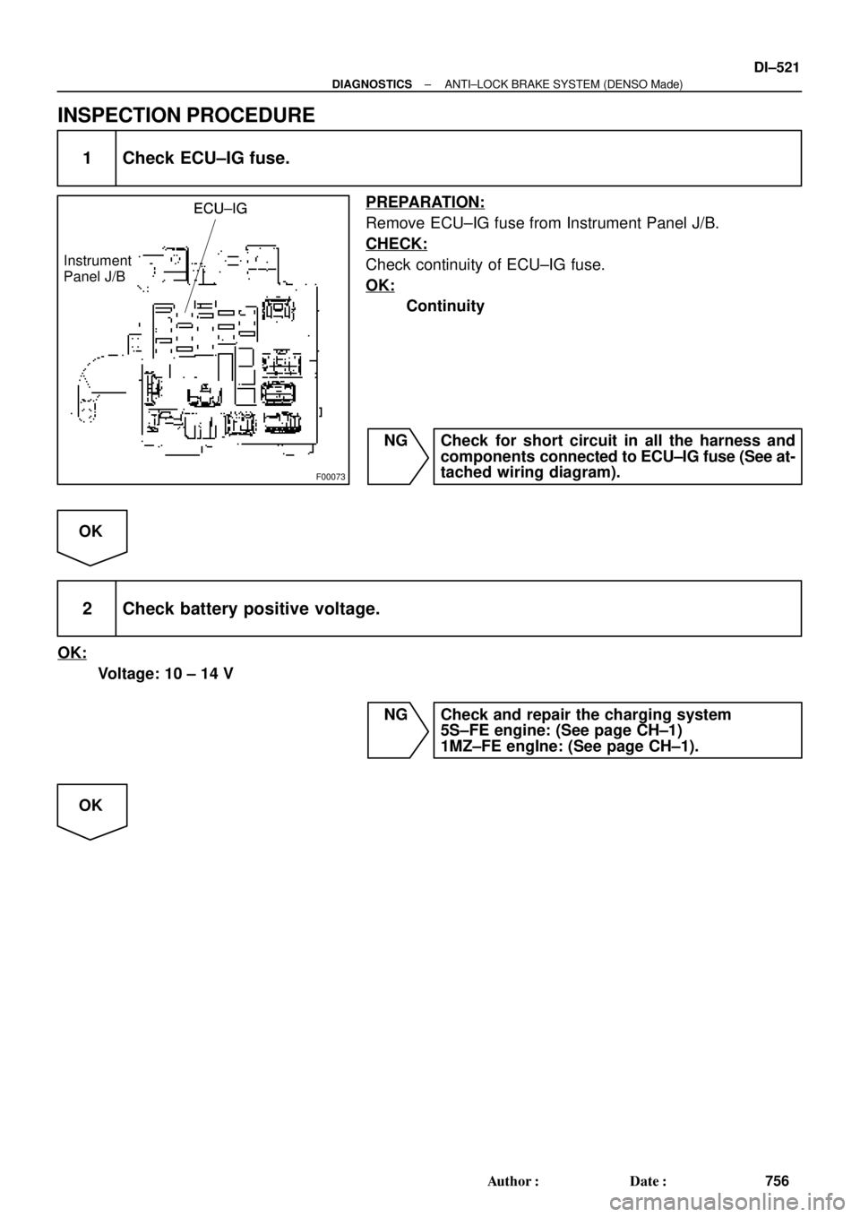
F00073
ECU±IGECU±IG
Instrument
Panel J/BECU±IG
± DIAGNOSTICSANTI±LOCK BRAKE SYSTEM (DENSO Made)
DI±521
756 Author�: Date�:
INSPECTION PROCEDURE
1 Check ECU±IG fuse.
PREPARATION:
Remove ECU±IG fuse from Instrument Panel J/B.
CHECK:
Check continuity of ECU±IG fuse.
OK:
Continuity
NG Check for short circuit in all the harness and
components connected to ECU±IG fuse (See at-
tached wiring diagram).
OK
2 Check battery positive voltage.
OK:
Voltage: 10 ± 14 V
NG Check and repair the charging system
5S±FE engine: (See page CH±1)
1MZ±FE engIne: (See page CH±1).
OK
Page 1735 of 4592

F00124
Battery MAIN B±GF4 F91
ALT FL Block
B±R STOP Instrument Panel J/B
1C1B4
7Stop Light
Switch
2G±W
1R 1S5J27 J28J/C
Light Failure
Sensor
J/C
J40
BL
BP W±BG±W
A195
STPABS ECU
R
G±R
High
Mounted
Stop
LightRight
Stop
LightLeft
Stop
Light
A 1Instrument
Panel J/B
G±R W
11R
2 4
G±W
G±R
W±B
W±B
W±B AAC
W±B W±BH10 R11
R9
H10R9
R11 2
122
5 5 G±W
1
2 7
Under the
Left Center
PillarBack Panel
Center
± DIAGNOSTICSANTI±LOCK BRAKE SYSTEM (DENSO Made)
DI±523
758 Author�: Date�:
DTC 49 Stop Light Switch Circuit
CIRCUIT DESCRIPTION
DTC No.DTC Detecting ConditionTrouble Area
49
ABS ECU terminal IG1 voltage is 9.5 V to 18.5 V and ABS
is in non±operation, the open circuit of the stop light switch
circuit continues for 0.3 sec. or more.�Stop light switch
�Stop light switch circuit
WIRING DIAGRAM
INSPECTION PROCEDURE
1 Check operation of stop light.
CHECK:
Check that stop light lights up when brake pedal is depressed and turns off when brake pedal is released.
NG Repair stop light circuit (See page BE±37).
OK
DI03N±03