Page 1596 of 4592

A07453
5
1B±R
1ECM Engine Room J/B
E77
STA
E1 S2
Starter W±B 9 5
2D
2K 3
2
Sarter Relay MAIN
2B3
2J 11 B
J7
J7 J8
Junction
Connector CB
B II210 From Battery
W±B
W±B
A
A J11
Junction
Connector
IG Instrument
Panel J/B
STARTER
From Ignition Switch11
II2
B±W(A/T)
B±W(A/T)
B±W
Park/Neutral
Position Switch 6
5
B±W(A/T)
B
B
B
1J
1K 3
4
B±W(M/T)
12
Clutch Start Switch
GR
*1GR1
*1B±O
*GR
*GR
*GR
*B±O(M/T)
J16
Junction
Connector
*B±O
*: TMMK made
*
1: TMC made
*1B±O
DI±384
± DIAGNOSTICSENGINE (1MZ±FE)
619 Author�: Date�:
Starter Signal Circuit
CIRCUIT DESCRIPTION
When the engine is cranked, the intake air flow is slow, so fuel vaporization is poor. A rich mixture is therefore
necessary in order to achieve good startability. While the engine is being cranked, the battery positive volt-
age is applied to terminal STA of the ECM. The starter signal is mainly used to increase the fuel injection
volume for the starting injection control and after±start injection control.
WIRING DIAGRAM
DI08B±06
Page 1620 of 4592

643 Author�: Date�:
CIRCUIT INSPECTION
DTC")
DI1J0±01
A00414
Vehicle Speed Sensor4±Pulse 4±Pulse
Combination Meter
ECM
Transaxle
Vehicle Speed Sensor
DI±408
± DIAGNOSTICSAUTOMATIC TRANSAXLE (A140E)
643 Author�: Date�:
CIRCUIT INSPECTION
DTC P0500 Vehicle Speed Sensor Malfunction
CIRCUIT DESCRIPTION
The vehicle speed sensor outputs a 4±pulse signal for every revolution of the rotor shaft, which is rotated
by the transmission output shaft via the driven gear. After this signal is converted into a more precise rectan-
gular wave form by the wave form shaping circuit inside the combination meter, it is then transmitted to the
ECM. The ECM determines the vehicle speed based on the frequency of these pluse signals.
DTC No.DTC Detecting ConditionTrouble Area
P0500
During vehicle is being driven, no vehicle speed sensor signal
to ECM
(2 trip detection logic)�Combination meter
�Open or short in vehicle speed sensor circuit
�Vehicle speed sensor
ECM Clutch or brake slips or gear is broken�ECM
�Automatic transaxle (clutch, brake or gear etc.)
WIRING DIAGRAM
See page DI±145.
Page 1626 of 4592
D01807
W3
E4 Transaxle
Shift Solenoid
Valve No.1
Shift Solenoid
Valve No.2
*2: w/o Engine
Immobiliser SystemE4 B1V7
21
*2
E9S1
*1: w/ Engine
Immobiliser System
A L ± B
*18
6
*2*1
E9
E9E9 L ± B J25
Junction
Connector
AAS2B+
B+
Cruise Control ECUECM
D00102 Q10102D00990
w/ Engine Immobiliser System
w/o Engine Immobiliser SystemS2
S1
S1
S2
DI±414
± DIAGNOSTICSAUTOMATIC TRANSAXLE (A140E)
649 Author�: Date�:
WIRING DIAGRAM
INSPECTION PROCEDURE
1 Measure resistance between terminal S1 or S2 of ECM and body ground.
PREPARATION:
Disconnect the connector from ECM.
CHECK:
Measure resistance between terminal S1 or S2 of ECM and
body ground.
OK:
Resistance: 11 ~ 15 W
OK Check and replace the ECM.
NG
Page 1631 of 4592
D01808
1
E3P
*1
Transaxle
Shift Solenoid
Valve SLECM
B+
: w/ Engine Immobiliser System
: w/o Engine Immobiliser SystemSL
E91 20
*1
*2
E9
*2
± DIAGNOSTICSAUTOMATIC TRANSAXLE (A140E)
DI±419
654 Author�: Date�:
DTC P0773 Shift Solenoid E Electrical Malfunction
(Shift Solenoid Valve SL)
CIRCUIT DESCRIPTION
The shift solenoid valve SL is turned ON and OFF by signals from the ECM to control the hydraulic pressure
acting on the lock±up relay valve, which then controls operation of the lock±up clutch.
Fail safe function
If the ECM detects a malfunction, it turns the shift solenoid valve SL OFF.
DTC No.DTC Detecting ConditionTrouble Area
P0773
Either (a) or (b) is detected for 1 time.(2 trip detection logic)
(a) Solenoid resistance is 8 W or less short circuit when sole-
noid is energized.
(b) Solenoid resistance is 100 kW or more open circuit when
solenoid is not energized.
�Open or short in shift solenoid valve SL circuit
�Shift solenoid valve SL
�ECM
WIRING DIAGRAM
DI035±02
Page 1635 of 4592
± DIAGNOSTICSAUTOMATIC TRANSAXLE (A140E)
DI±423
658 Author�: Date�:
DTC P1520 Stop Light Switch Signal Malfunction
CIRCUIT DESCRIPTION
The purpose of this circuit is to prevent the engine from stalling, while driving in lock±up condition, when
brakes are suddenly applied.
When the brake pedal is depressed, this switch sends a signal to ECM. Then the ECM cancels operation
of the lock±up clutch while braking is in progress.
DTC No.DTC Detecting ConditionTrouble Area
P1520No stop light switch signal to ECM during driving.
(2 trip detection logic)�Open or short in stop light switch circuit
�Stop light switch
�ECM
WIRING DIAGRAM
See page DI±170.
INSPECTION PROCEDURE
See page DI±170.
DI036±02
Page 1637 of 4592

D01820
Combination
Meter
R
C8R ± B
13
IG13
2
L8
11
6 C8
C8O
Y16
IG13
*3 L ± W
*4 O
1HInstrument
Panel J/BECM
1V Park/Neutral
Position Switch
P1
L ± W
B ± WII2
E
8 34
P1
P1 P12Y
R ± BII2
J29
Junction
Connector E
E
Y10
5
Y19
15
*1
*2
E7
E7
E7
E7
E7
E7R2 L
1816
*1
*2
17
22B
+
NSW *3 L ± W
*4 O
R ± B
R ± B
B ± W
DD
D
J29
Junction
Connector
J27J27
J28 CC
A
R ± B
B ± W 5
6
3
11II3
II2
B
BB R ± L A
A
J21
Junction
Connector
J28
Junction
Connector
5 2II2R ± L
F
F6
B ± R
F9
ALT
B ± G
B ± R
1
112F9
F4F6
FL
MAIN
BatteryAM1
1B
2L12
55 1B
1K1K
2A 41
AM2 W ± R
B GR
II2
W ± R
10*5
*6GR
B ± O
C
J8B*5
*6GR
B ± O
BW2
74
8 I16 I16
I16 I16Ignition Switch
B ± Y
R11
43 1K
1K1J
1J GAUGE
STARTER
MAINST Relay
2BB ± W
3
115
9
2J2D
2K 5
3
12 Y
J29
Junction
Connector
J27, J28
Junction Connector
*3 L ± W
*4 O
Instrument Panel J/B
Instrument Panel J/B Instrument Panel J/B
Engine Room J/B No.2
J11 Junction Connector
*1: w/ Engine Immobiliser System
*2: w/o Engine Immobiliser System
*3: TMC Made*4: TMMK Made
*5: TMC Made w/o Traction Control
*6: Except TMC Made w/o Traction ControlInstrument Panel J/B
Starter
J7A
IK R ± L
J7 J8 Junction Connector Engine Room J/B No.2 R ± L
± DIAGNOSTICSAUTOMATIC TRANSAXLE (A140E)
DI±425
660 Author�: Date�:
WIRING DIAGRAM
Page 1640 of 4592
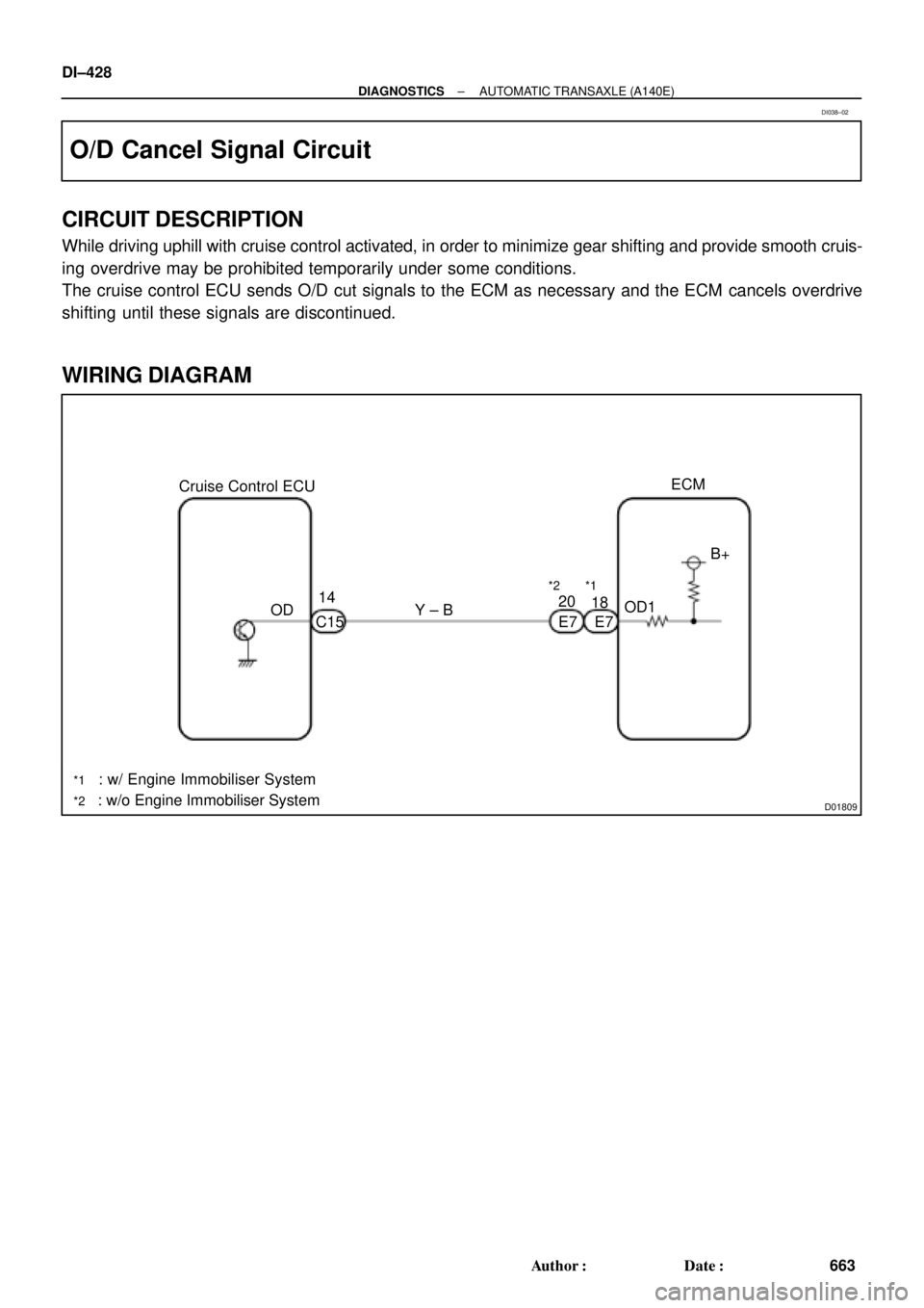
D01809
Cruise Control ECU
: w/ Engine Immobiliser System
: w/o Engine Immobiliser SystemOD14
C15Y ± B
*1
20
E7OD1B+ ECM
*2
18
E7
*1
*2
DI±428
± DIAGNOSTICSAUTOMATIC TRANSAXLE (A140E)
663 Author�: Date�:
O/D Cancel Signal Circuit
CIRCUIT DESCRIPTION
While driving uphill with cruise control activated, in order to minimize gear shifting and provide smooth cruis-
ing overdrive may be prohibited temporarily under some conditions.
The cruise control ECU sends O/D cut signals to the ECM as necessary and the ECM cancels overdrive
shifting until these signals are discontinued.
WIRING DIAGRAM
DI038±02
Page 1643 of 4592

D01810
: w/ Engine Immobiliser System
: w/o Engine Immobiliser System
: O/D Main Switch
Contacts go open with switch pushed in
Contacts go closed with switch pushed once againInstrument
Panel J/BIgnition Switch
1B1
AM1
W
I16
7 1
22
1K2
AM1 IG1
B ± Y
O/D OFF
Indicator Light
(Combination Meter) R ± L
R ± LGAUGE
J4
Junction
Connector
DI164
2
1D 1K
D12
C8G ± OC
C8
W ± B C
CG ± O
G ± OJ6
Junction
ConnectorECM
5
*1B+
E77*2
E7OD2G ± O
IG311
O2 2
(*3)
O/D Main
Switch
O2
4
W ± B A
IF AJ5
Junction
Connector B ± R
1
FUSIBLE
LINK
BLOCKALT F9B ± R
2
F9
1
F4B ± GFL
MAIN
Battery
*3 *2 *1
1 Instrument
Panel J/B
± DIAGNOSTICSAUTOMATIC TRANSAXLE (A140E)
DI±431
666 Author�: Date�:
O/D Main Switch & O/D OFF Indictor Light Circuit
CIRCUIT DESCRIPTION
The O/D main switch contacts go open when the switch is pushed in and go closed when it is pushed out.
In O/D main switch in OFF position, the O/D OFF indicator light lights up, and the ECM prohibits shifting over-
drive.
WIRING DIAGRAM
DI1J1±01


DI±419
654 Author")