Page 1491 of 4592

DI±279
514 Author�: Date�:
2 Check spark plug and spark of misfiring cylinder.
PREPARATION:
(a) Remove the ignition coil (See page IG±7).
(b) Remov")
A00221P25779
P23917
± DIAGNOSTICSENGINE (1MZ±FE)
DI±279
514 Author�: Date�:
2 Check spark plug and spark of misfiring cylinder.
PREPARATION:
(a) Remove the ignition coil (See page IG±7).
(b) Remove the spark plug.
CHECK:
(a) Check spark plug type.
(b) Check for carbon deposits on electrode.
(c) Check electrode gap.
OK:
(a) Twin ground electrodes type.
Recommended spark plug:
ND PK20TR11
NGK BKR6EKPB±11
(b) No large carbon deposit present.
Not wet with gasoline or oil.
(c) Electrode gap:
Standerd: 1.0 ± 1.1 mm (0.03937 ± 0.043 in.).
Maximum: 1.3 mm (0.051 in.).
PREPARATION:
(a) Install the spark plug to the ignition coil, and connect the
ignition coil the connector.
(b) Disconnect injector connector.
(c) Hold the end about 12.5 mm (0.5 in.) from the ground.
CHECK:
Check if spark occurs while engine is being cranked.
NOTICE:
To prevent excess fuel being injected from the
injectors during this test, don't crank the engine for more
than 5 ~ 10 sec. at a time.
OK:
Spark jumps across electrode gap.
NG Replace or check ignition system
(See page IG±1).
OK
Page 1607 of 4592

± DIAGNOSTICSAUTOMATIC TRANSAXLE (A140E)
DI±395
630 Author�: Date�:
(c) Replace the ATF.
(1) Remove the drain plug and drain")
Q00061
AT8562
AT3417
OK if hot
Add if hot
AT4252
0 ~ 1 mm (0 ~ 0.04 in.)
± DIAGNOSTICSAUTOMATIC TRANSAXLE (A140E)
DI±395
630 Author�: Date�:
(c) Replace the ATF.
(1) Remove the drain plug and drain the fluid.
(2) Reinstall the drain plug securely.
(3) With the engine OFF add new fluid through the oil
filler pipe.
Fluid type: ATF D±II or DEXRON®III (DEXRON®II)
Capacity: 2.5 liters (2.6 US qts, 2.1 Imp. qts)
(4) Start the engine and shift the shift lever into all posi-
tions from P to L position and then shift into P posi-
tion.
(5) With the engine idling, check the fluid level. Add
fluid up to the COOL level on the dipstick.
(6) Check the fluid level is at the normal operating tem-
perature, 70 ± 80 °C (158 ± 176 °F), and add as
necessary.
NOTICE:
Do not overfill.
(d) Check the fluid leaks.
Check for leaks in the transaxle.
If there are leaks, it is necessary to repair or replace O±rings,
gasket, oil seals, plugs or other parts.
(e) Inspect and adjust the throttle cable.
(1) Check that the accelerator pedal is fully released.
(2) Check that the inner cable is not slack.
(3) Measure the distance between the outer cable end
and stopper on the cable.
Standard distance: 0 ± 1 mm (0 ± 0.04 in.)
If the distance is not standard, adjust the cable by the adjusting
nuts.
Page 1656 of 4592
 DI±444
± DIAGNOSTICSAUTOMATIC TRANSAXLE (A541E)
679 Author�: Date�:
(c) Replace the ATF.
(1) Remove the drain plug and drain")
AT4657
AT8562
AT3417
OK if hot
Add if hot
AT4252
0 ~ 1 mm (0 ~ 0.04 in.) DI±444
± DIAGNOSTICSAUTOMATIC TRANSAXLE (A541E)
679 Author�: Date�:
(c) Replace the ATF.
(1) Remove the drain plug and drain the fluid.
(2) Reinstall the drain plug securely.
(3) With the engine OFF add new fluid through the oil
filler pipe.
Fluid type: ATF D±II or DEXRON®III (DEXRON®II)
Capacity: 3.9 liters (4.1 US qts, 3.4 Imp. qts)
(4) Start the engine and shift the shift lever into all posi-
tions from P to L position and then shift into P posi-
tion.
(5) With the engine idling, check the fluid level. Add
fluid up to the COOL level on the dipstick.
(6) Check the fluid level at the normal operating tem-
perature, 70 ± 80 °C (158 ± 176 °F), and add as
necessary.
NOTICE:
Do not overfill.
(d) Check the fluid leaks.
Check for leaks in the transaxle.
If there are leaks, it is necessary to repair or replace O±rings,
gasket, oil seals, plugs or other parts.
(e) Inspect and adjust the throttle cable.
(1) Check that the accelerator pedal is fully released.
(2) Check that the inner cable is not slack.
(3) Measure the distance between the outer cable end
and stopper on the cable.
Standard distance: 0 ± 1 mm (0 ± 0.04 in.)
If the distance is not the standard, adjust the cable by the ad-
justing nuts.
Page 2165 of 4592

DI00I±11
DI±14
± DIAGNOSTICSENGINE
DIAGNOSTIC TROUBLE CODE CHART
HINT:
Parameters listed in the chart may not be exactly the same as your reading due to the type of instrument
or other factors.
If a malfunction code is displayed during the DTC check in check mode, check the circuit for that code listed
in the table below. For details of each code, turn to the page referred to under the ''See page '' for the respec-
tive ''DTC No.'' in the DTC chart.
1. SAE CONTROLLED
DTC No.
(See page)Detection ItemTrouble AreaMIL*Memory
P0105
(DI±22)Manifold Absolute Pressure/
Barometric Pressure Circuit Mal-
function�Open or short in manifold absolute pressure sensor circuit
�Manifold absolute pressure sensor
�ECM
��
P0106
(DI±25)Manifold Absolute Pressure Cir-
cuit Range/Performance Prob-
lem�Vacuum line
�Manifold absolute pressure sensor��
P0110
(DI±26)Intake Air Temp. Circuit Malfunc-
tion�Open or short in intake air temp. sensor circuit
�Intake air temp. sensor
�ECM
��
P0115
(DI±30)Engine Coolant Temp. Circuit
Malfunction�Open or short in engine coolant temp. sensor circuit
�Engine coolant temp. sensor
�ECM
��
P0116
(DI±34)Engine Coolant Temp. Circuit
Range/Performance Problem�Cooling system
�Engine coolant temp. sensor��
P0120
(DI±35)Throttle/Pedal Position Sensor/
Switch ºAº Circuit Malfunction�Open or short in throttle position sensor circuit
�Throttle position sensor
�ECM
��
P0121
(DI±39)Throttle/Pedal Position Sensor/
Switch ºAº Circuit Range/Perfor-
mance Problem
�Throttle position sensor��
P0125
(DI±40)Insufficient Coolant Temp. for
Closed Loop Fuel Control
�Open or short in A/F sensor (bank 1 sensor 1) circuit
�A/F sensor (bank 1 sensor 1)
�Air induction system
�EGR system
�Fuel pressure
�Injector
�Gas leakage on exhaust system
�ECM
��
P0136
(DI±45)Oxygen Sensor Circuit Malfunc-
tion (Bank 1 Sensor 2)�Open or short in heated oxygen sensor circuit
�Heated oxygen sensor��
P0141
(DI±47)Oxygen Sensor Heater Circuit
Malfunction (Bank 1 Sensor 2)�Open or short in heater circuit of heated oxygen sensor
�Heated oxygen sensor heater
�ECM
��
P0171
(DI±49)System too Lean (Fuel Trim)
�Air induction system
�Injector blockage
�Manifold absolute pressure sensor
�Engine coolant temp. sensor
�Fuel shutoff valve for delivery pipe
�Gas leakage on exhaust system
�Open or short in A/F sensor (bank 1 sensor 1) circuit
�A/F sensor (bank 1 sensor 1)
�ECM
��
Page 2291 of 4592

± DIAGNOSTICSAUTOMATIC TRANSAXLE
DI±139
(c) Replace the ATF.
(1) Remove the drain plug and drain the fluid.
(2) Reinstall t")
Q00061
AT8562
AT3417
OK if hot
Add if hot
AT4252
0 ± 1 mm (0 ± 0.04 in.)
± DIAGNOSTICSAUTOMATIC TRANSAXLE
DI±139
(c) Replace the ATF.
(1) Remove the drain plug and drain the fluid.
(2) Reinstall the drain plug securely.
(3) With the engine OFF add new fluid through the oil
filler pipe.
Fluid type: ATF D±II or DEXRON®III (DEXRON®II)
Capacity: 2.5 liters (2.6 US qts, 2.1 Imp. qts)
(4) Start the engine and shift the shift lever into all posi-
tions from P to L position and then shift into P posi-
tion.
(5) With the engine idling, check the fluid level. Add
fluid up to the COOL level on the dipstick.
(6) Check the fluid level is at the normal operating tem-
perature, 70 ± 80 °C (158 ± 176 °F), and add as
necessary.
NOTICE:
Do not overfill.
(d) Check the fluid leaks.
Check for leaks in the transaxle.
If there are leaks, it is necessary to repair or replace O±rings,
gasket, oil seals, plugs or other parts.
(e) Inspect and adjust the throttle cable.
(1) Check that the accelerator pedal is fully released.
(2) Check that the inner cable is not slack.
(3) Measure the distance between the outer cable end
and stopper on the cable.
Standard distance: 0 ± 1 mm (0 ± 0.04 in.)
If the distance is not standard, adjust the cable by the adjusting
nuts.
Page 2522 of 4592
EVAPORATIVE EMISSION (EVAP) CONTROL SYSTEM
1404 Author�: Date�:
INSPECTION
1. INSPE")
EC03E±05
B01082B04812B06707
Type A
Type BGasket
Gasket
B06544
Vacuum
Gauge
S05331
EC±6
± EMISSION CONTROL (5S±FE)EVAPORATIVE EMISSION (EVAP) CONTROL SYSTEM
1404 Author�: Date�:
INSPECTION
1. INSPECT LINES AND CONNECTORS
Visually check for loose connections, sharp bends or damage.
2. INSPECT FUEL TANK FILLER PIPE
Visually check for deformation, cracks or fuel leakage.
3. INSPECT FUEL TANK CAP
Visually check if the cap and/or gasket are deformed or dam-
aged.
If necessary, repair or replace the cap.
4. INSPECT EVAP SYSTEM LINE
(a) Warm up the engine and stop the engine.
Allow the engine to warm up to normal operating tempera-
ture.
(b) Install a vacuum gauge (EVAP control system test equip-
ment vacuum gauge) to the EVAP service port on the
purge line.
(c) TOYOTA Hand±Held Tester:
Forced driving of the VSV for the EVAP.
(1) Connect a TOYOTA hand±held tester to the DLC3.
(2) Start the engine.
(3) Push the TOYOTA hand±held tester main switch
ON.
(4) Use the ACTIVE TEST mode on the TOYOTA
hand±held tester to operate the VSV for the EVAP.
Page 2539 of 4592
EVAPORATIVE EMISSION (EVAP) CONTROL SYSTEM
1421 Auth")
EC0AV±01
B01082B04812B06707
Type A
Type BGasket
Gasket
B06544
Vacuum
Gauge
S05331
TOYOTA
Hand±Held Tester
DLC3
EC±6
± EMISSION CONTROL (1MZ±FE)EVAPORATIVE EMISSION (EVAP) CONTROL SYSTEM
1421 Author�: Date�:
INSPECTION
1. INSPECT LINES AND CONNECTORS
Visually check for loose connections, sharp bends or damage.
2. INSPECT FUEL TANK FILLER PIPE
Visually check for deformation, cracks or fuel leakage.
3. INSPECT FUEL TANK CAP
Visually check if the cap and/or gasket are deformed or dam-
aged.
If necessary, repair or replace the cap.
4. INSPECT EVAP SYSTEM LINE
(a) Warm up the engine and stop the engine.
Allow the engine to warm up to normal operating tempera-
ture.
(b) Install a vacuum gauge (EVAP control system test equip-
ment vacuum gauge) to the EVAP service port on the
purge line.
(c) TOYOTA Hand±Held Tester:
Forced driving of the VSV for the EVAP.
(1) Connect a TOYOTA hand±held tester to the DLC3.
(2) Start the engine.
(3) Push the TOYOTA hand±held tester main switch
ON.
(4) Use the ACTIVE TEST mode on the TOYOTA
hand±held tester to operate the VSV for the EVAP.
Page 2548 of 4592
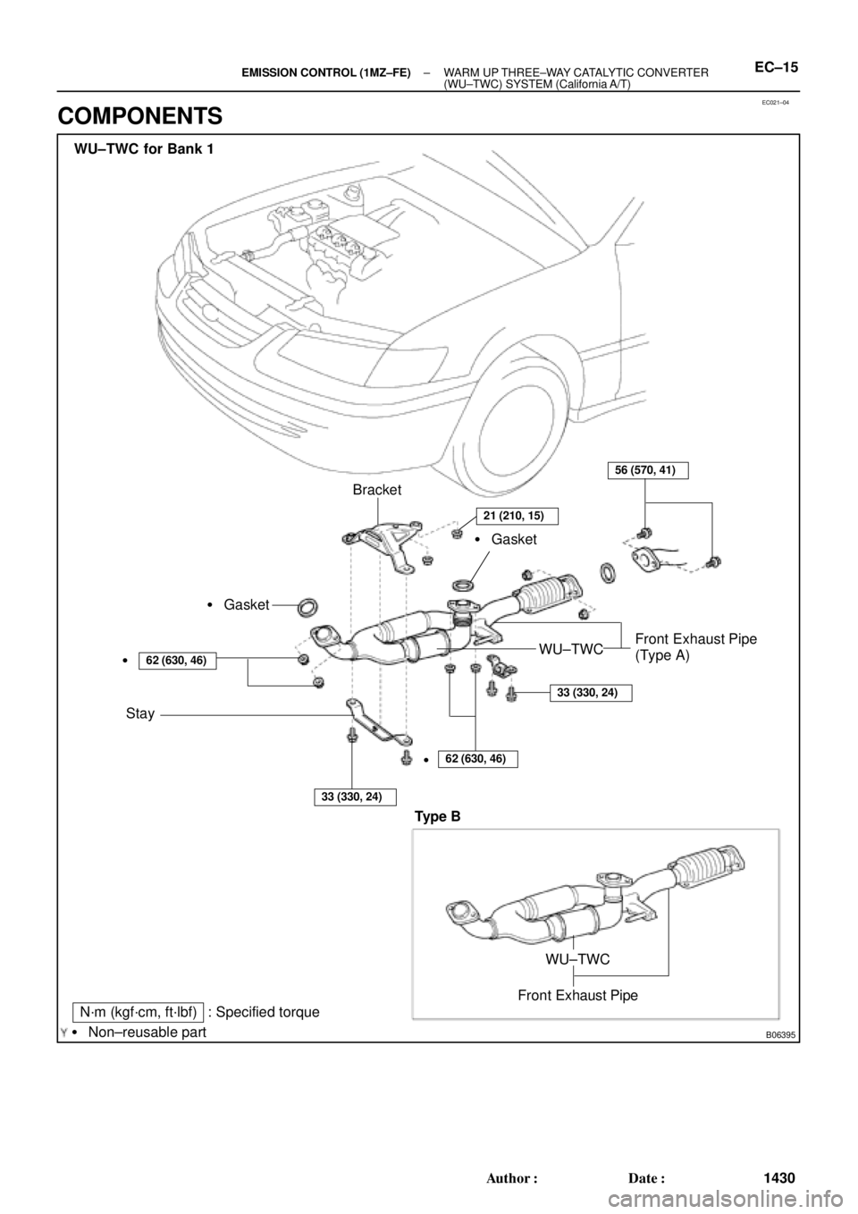
EC021±04
B06395
N´m (kgf´cm, ft´lbf) : Specified torque
� Non±reusable partBracket
� Gasket
Stay
62 (630, 46)
33 (330, 24)
56 (570, 41)
WU±TWCFront Exhaust Pipe
(Type A) � Gasket
�
62 (630, 46)
33 (330, 24)
WU±TWC for Bank 1
�
21 (210, 15)
Front Exhaust Pipe
WU±TWC
Type B
± EMISSION CONTROL (1MZ±FE)WARM UP THREE±WAY CATALYTIC CONVERTER
(WU±TWC) SYSTEM (California A/T)EC±15
1430 Author�: Date�:
COMPONENTS