Page 3332 of 4592
S06038
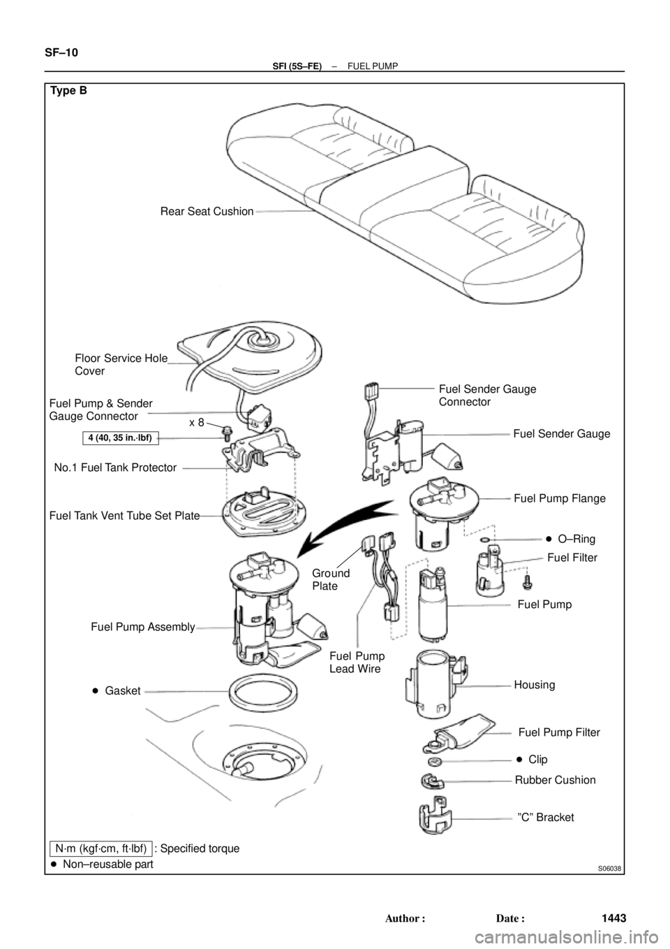
Type B
Rear Seat Cushion
� Gasket
4 (40, 35 in.´lbf)
Floor Service Hole
Cover
Fuel Pump & Sender
Gauge Connector
No.1 Fuel Tank Protector
Fuel Tank Vent Tube Set Plate
Fuel Filter Fuel Pump Flange
Fuel Pump
Fuel Pump Filter
� Clip
Rubber Cushion Fuel Pump Assembly
N´m (kgf´cm, ft´lbf)
� Non±reusable part� O±Ring
Housing
ºCº Bracket Fuel Sender Gauge
Fuel Pump
Lead Wire
: Specified torqueFuel Sender Gauge
Connector
Ground
Plate
x 8
SF±10
± SFI (5S±FE)FUEL PUMP
1443 Author�: Date�:
Page 3333 of 4592
FUEL PUMP
SF±11
1444 Author�: Date�:
REMOVAL
CAUTION:
Do not smoke or work near an open flame when working on
the fuel pump.
1. REMOVE REAR SEAT CUSHI")
SF0D9±03
S04583
S04592
Vinyl Bag
± SFI (5S±FE)FUEL PUMP
SF±11
1444 Author�: Date�:
REMOVAL
CAUTION:
Do not smoke or work near an open flame when working on
the fuel pump.
1. REMOVE REAR SEAT CUSHION
2. REMOVE FLOOR SERVICE HOLE COVER
(a) Take out the floor carpet.
(b) Remove the service hole cover.
HINT:
At the time of installation, please refer to the following items.
Check for fuel leakage.
3. DISCONNECT FUEL PUMP & SENDER GAUGE CON-
NECTOR
4. REMOVE NO.1 FUEL TANK PROTECTOR
Remove the 2 bolts and No.1 fuel tank protector.
Torque: 4 N´m (40 kgf´cm, 35 in.´lbf)
5. DISCONNECT FUEL TUBE (FUEL TUBE CONNEC-
TOR)
CAUTION:
�Perform disconnecting and connecting operations of
the fuel tube connector (quick type) after observing
the precautions.
�As there is retained pressure in the fuel pipe line, pre-
vent it from splashing inside the vehicle compart-
ment.
6. REMOVE FUEL PUMP ASSEMBLY FROM FUEL TANK
(a) Remove the 6 bolts and fuel tank vent tube set plate.
Torque: 4 N´m (40 kgf´cm, 35 in.´lbf)
(b) Pull out the fuel pump assembly.
(c) Remove the gasket from the pump assembly.
NOTICE:
�Do not damage the fuel pump filter.
�Be careful that the arm of the sender gauge should
not bent.
HINT:
At the time of installation, please refer to the following items.
Install a new gasket to the pump assembly.
Page 3334 of 4592
(3)
(2) Type B SF±12
± SFI (5S±FE)FUEL PUMP
1445 Author�: Date�:
DISASSEMBLY
1. DISCONNECT FUEL PUMP CONNECTOR")
SF0DA±02
S06028
Type B
S04603Pull Type A
S06033
PushA Type B
S06050
Type B
S06030
(1)(3)
(2) Type B SF±12
± SFI (5S±FE)FUEL PUMP
1445 Author�: Date�:
DISASSEMBLY
1. DISCONNECT FUEL PUMP CONNECTOR
2. Type B:
DISCONNECT GROUND PLATE
3. Type B:
DISCONNECT FUEL SENDER GAUGE CONNECTOR
4. Type A:
REMOVE FUEL PUMP FROM FUEL PUMP BRACKET
(a) Pull off the lower side of the fuel pump from the pump
bracket.
(b) Disconnect the fuel hose from the fuel pump, and remove
the fuel pump.
(c) Remove the rubber cushion from the fuel pump.
5. Type B:
REMOVE FUEL SENDER GAUGE.
Push down the portion of A with a finger, and push up the send-
er gauge.
NOTICE:
Be careful that the arm of the sender gauge should not
bent.
6. Type B:
REMOVE FUEL FILTER
(a) Remove the screw, and pull out the fuel filter.
(b) Remove the O±ring from the fuel filter.
HINT:
At the time of installation, please refer to the following items. Ap-
ply a light coat of gasoline to a new O±ring, and install it to the
fuel filter.
Torque: 2.0 N´m (20 kgf´cm, 17 in.´lbf)
7. Type B:
REMOVE FUEL PUMP FLANGE
Using a screwdriver, remove the snap fit portion in the order of
1, 2 and 3 as shown in the illustration.
HINT:
At the time of installation, please refer to the following items. Ap-
ply a light coat of gasoline to a new O±ring of the fuel pump.
Page 3338 of 4592
SF0DD±02
Z19026
Type A
Rear Seat Cushion
Floor Service Hole Cover
Fuel Pump & Sender
Gauge Connector
No.1 Fuel Tank Protector
Fuel Tank Vent Tube Set Plate
Fuel Pressure
Regulator
Fuel Filter Fuel Pump Assembly
� Gasket
N´m (kgf´cm, ft´lbf)� O±Ring � O±Ring
� Non±reusable part
4 (40, 35 in.´lbf)
: Specified torquex 8
SF±16
± SFI (5S±FE)FUEL PRESSURE REGULATOR
1449 Author�: Date�:
FUEL PRESSURE REGULATOR
COMPONENTS
Page 3339 of 4592
S06037
Type B
Rear Seat Cushion
Floor Service Hole Cover
Fuel Pump and Sender
Gauge Connector
No.1 Fuel Tank Protector
Fuel Tank Vent Tube Set Plate
Fuel Pressure
Regulator
Fuel Filter Fuel Pump Assembly
� Gasket
N´m (kgf´cm, ft´lbf)� O±Ring � O±Ring
� Non±reusable part
4 (40, 35 in.´lbf)
: Specified torquex 8
± SFI (5S±FE)FUEL PRESSURE REGULATOR
SF±17
1450 Author�: Date�:
Page 3392 of 4592
SFI")
B00630
O±Ring
Grommet
Spacer InsulatorDelivery Pipe California A/T
Except California A/TO±Ring
O±Ring
Grommet
Spacer InsulatorDelivery Pipe
O±Ring
S04583
S05040
Vinyl Bag SF±4
± SFI (1MZ±FE)SFI SYSTEM
1503 Author�: Date�:
(e) Install the injector to the delivery pipe and intake manifold,
as shown in the illustration.
Before installing the injector, must apply spindle oil or gas-
oline on the place where a delivery pipe or an intake man-
ifold touches an O±ring of the injector.
(f) Observe these precautions when disconnecting the fuel
tube connector (quick type).
(1) Check if there is any dirt like mud on the pipe and
around the connector before disconnecting them
and clean the dirt away.
(2) Be sure to disconnect with hands.
(3) When the connector and the pipe are stuck, pinch
the retainer between the hands, push and pull the
connector to free to disconnect and pull it out. Do
not use any tool at this time.
(4) Inspect if there is any dirt or the likes on the seal sur-
face of the disconnected pipe and clean it away.
(5) Prevent the disconnected pipe and connector from
damaging and mixing foreign objects by covering
them with a vinyl bag.
Page 3395 of 4592

Pipe
SST
(Hose)SST
± SFI (1MZ±FE)FUEL PUMP
SF±7
1506 Author�: Date�:
(d) Remove the fuel hose clamp.
(e) D")
S06086
Fuel Hose
Clamp
S05352
S05364
SST
SST
Retainer
No.1 Fuel
Fuel Tube
Connector (Hose)
Pipe
SST
(Hose)SST
± SFI (1MZ±FE)FUEL PUMP
SF±7
1506 Author�: Date�:
(d) Remove the fuel hose clamp.
(e) Disconnect the No.1 fuel pipe (fuel tube connector) from
the fuel filter outlet.
CAUTION:
�Perform disconnecting operations of the fuel tube
connector (quick type) after observing the precau-
tions. (See page SF±1)
�As there is retained pressure in the fuel pipe line, pre-
vent it from splashing inside the engine compart-
ment.
(f) Install SST (pressure gauge) as shown in the illustration
by using SST and fuel tube connector.
SST 09268±41047, 09268±41250, 09268±45012
(g) Wipe off any splattered gasoline.
(h) Reconnect the negative (±) terminal cable to the battery.
(i) Connect the TOYOTA hand held tester to the DLC3.
(See step 1. check fuel pump operation (a) to (e))
(j) Measure the fuel pressure.
Fuel pressure:
301 ± 347 kPa (3.1 ± 3.5 kgf/cm
2, 44 ± 50 psi)
If pressure is high, replace the fuel pressure regulator.
If pressure is low, check these parts:
Fuel hoses and connections
Fuel pump
Fuel filter
Fuel pressure regulator
(k) Disconnect the TOYOTA hand±held tester from the
DLC3.
(l) Start the engine.
(m) Measure the fuel pressure at idle.
Fuel pressure:
301 ± 347 kPa (3.1 ± 3.5 kgf/cm
2, 44 ± 50 psi)
(n) Stop the engine.
(o) Check that the fuel pressure remains as specified for 5
minutes after the engine has stopped.
Fuel pressure:
147 kPa (1.5 kgf/cm
2, 21 psi) or more
If pressure is not as specified, check the fuel pump, pressure
regulator and/or injectors.
Page 3396 of 4592
FUEL PUMP
1507 Author�: Date�:
(p) After checking fuel pressure, disconnect the negative (±)
terminal cable")
S05351
S06086
Fuel Hose
Clamp
S04508
Ohmmeter
4 5
S04509
4 5
Battery SF±8
± SFI (1MZ±FE)FUEL PUMP
1507 Author�: Date�:
(p) After checking fuel pressure, disconnect the negative (±)
terminal cable from the battery and carefully remove the
SST and fuel tube connector to prevent gasoline from
splashing.
SST 09268±41047, 09268±41250, 09268±45012
(q) Reconnect the No.1 fuel pipe (fuel tube connector).
CAUTION:
Perform connecting operations of the fuel tube connector
(quick type) after observing the precautions.
(See page SF±1)
(r) Surely install the fuel hose clamp to the fuel filter with
ºclickº sound.
(s) After installing the clamp, check that the clamp is fixed by
pulling up the clamp.
(t) Reconnect the negative (±) terminal cable to the battery.
(u) Check for fuel leaks.
3. REMOVE REAR SEAT CUSHION
4. REMOVE FLOOR SERVICE HOLE COVER
5. DISCONNECT FUEL PUMP & SENDER GAUGE
CONNECTOR
6. INSPECT FUEL PUMP RESISTANCE
Using an ohmmeter, measure the resistance between terminals
4 and 5.
Resistance: 0.2 ± 3.0 W at 20°C (68°F)
If the resistance is not as specified, replace the fuel pump.
7. INSPECT FUEL PUMP OPERATION
Connect the positive (+) lead from the battery to terminal 4 of
the connector, and the negative (±) lead to terminal 5. Check
that the fuel pump operates.
NOTICE:
�These tests must be done quickly (within 10 seconds)
to prevent the coil burning out.
�Keep the fuel pump as far away from the battery as
possible.
�Always do the switching at the battery side.