Page 3398 of 4592
SF07A±02
B06401
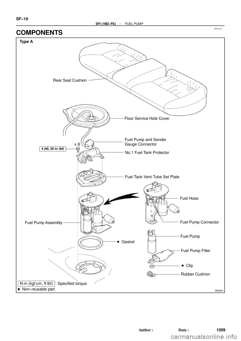
Type A
Rear Seat Cushion
� Gasket
4 (40, 35 in.´lbf)
Floor Service Hole Cover
Fuel Pump and Sender
Gauge Connector
No.1 Fuel Tank Protector
Fuel Tank Vent Tube Set Plate
Fuel Hose
Fuel Pump Connector
Fuel Pump
Fuel Pump Filter
Rubber Cushion
N´m (kgf´cm, ft´lbf)
� Non±reusable part: Specified torque
� Clip
Fuel Pump Assembly
x 8
SF±10
± SFI (1MZ±FE)FUEL PUMP
1509 Author�: Date�:
COMPONENTS
Page 3399 of 4592
B06394
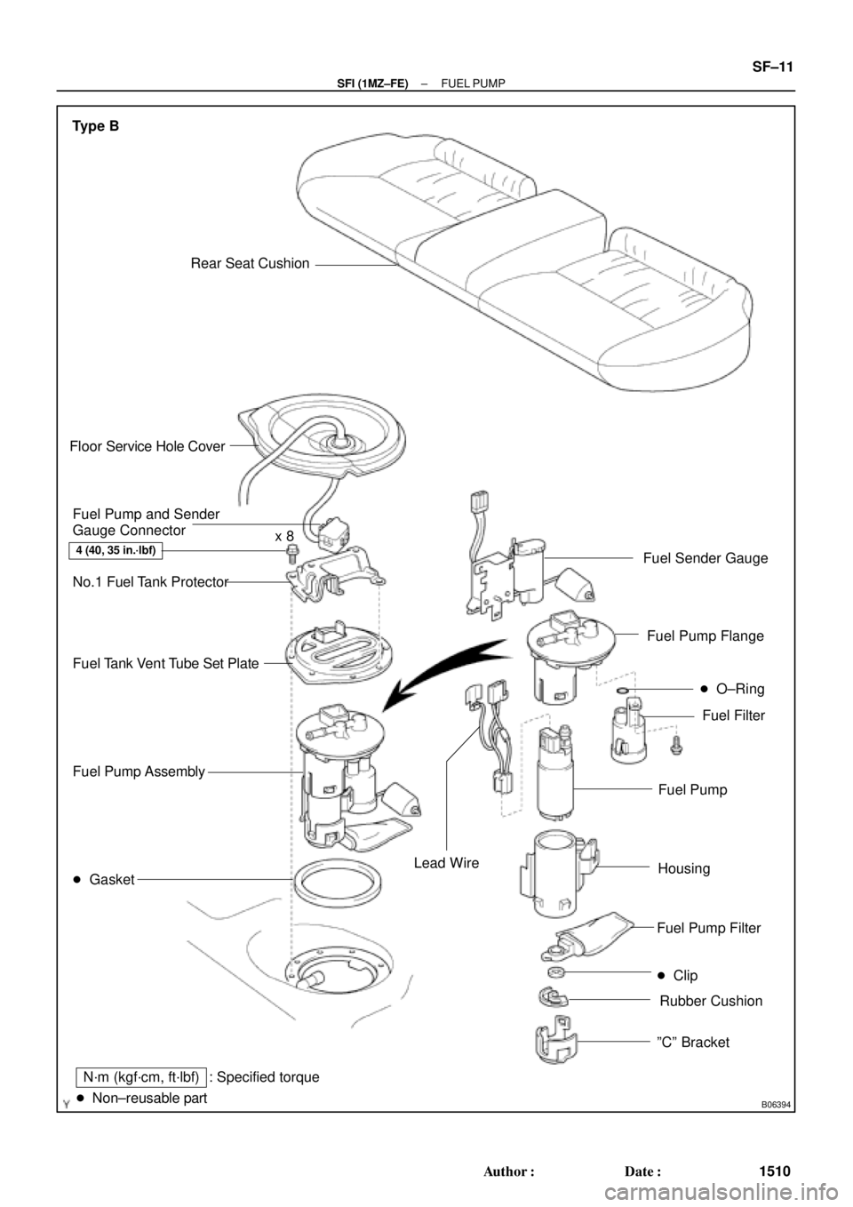
Type B
Rear Seat Cushion
� Gasket
4 (40, 35 in.´lbf)
Floor Service Hole Cover
Fuel Pump and Sender
Gauge Connector
No.1 Fuel Tank Protector
Fuel Tank Vent Tube Set Plate
N´m (kgf´cm, ft´lbf) : Specified torque Fuel Pump Assemblyx 8
� Clip
Rubber Cushion Fuel Pump FilterFuel Pump
HousingFuel Filter
ºCº Bracket
� O±Ring
Fuel Sender Gauge
Fuel Pump Flange
Lead Wire
� Non±reusable part
± SFI (1MZ±FE)FUEL PUMP
SF±11
1510 Author�: Date�:
Page 3400 of 4592
FUEL PUMP
1511 Author�: Date�:
REMOVAL
CAUTION:
Do not smoke or work near an open flame when working on
the fuel pump.
1. REMOVE REAR SEAT CUSH")
SF07B±04
S04583
S04592
Vinyl Bag SF±12
± SFI (1MZ±FE)FUEL PUMP
1511 Author�: Date�:
REMOVAL
CAUTION:
Do not smoke or work near an open flame when working on
the fuel pump.
1. REMOVE REAR SEAT CUSHION
2. REMOVE FLOOR SERVICE HOLE COVER
(a) Take out the floor carpet.
(b) Remove the service hole cover.
HINT:
At the time of installation, plaese refer to the following items.
Check for fuel leakage.
3. DISCONNECT FUEL PUMP & SENDER GAUGE
CONNECTOR
4. REMOVE NO.1 FUEL TANK PROTECTOR
Remove the 2 bolts and No.1 fuel tank protector.
Torque: 4 N´m (40 kgf´cm, 35 in.´lbf)
5. DISCONNECT FUEL TUBE (FUEL TUBE CONNEC-
TOR)
CAUTION:
�Perform disconnecting and connecting operations of
the fuel tube connector (quick type) after observing
the precautions. (See page SF±1)
�As there is retained pressure in the fuel pipe line, pre-
vent it from splashing inside the vehicle compart-
ment.
6. REMOVE FUEL PUMP ASSEMBLY FROM FUEL TANK
(a) Remove the 6 bolts and fuel tank vent tube set plate.
Torque: 4 N´m (40 kgf´cm, 35 in.´lbf)
(b) Pull out the fuel pump assembly.
(c) Remove the gasket from the pump assembly.
NOTICE:
�Do not damage the fuel pump filter.
�Be careful that the arm of the sender gauge should
not bent.
HINT:
At the time of installation, plaese refer to the following items.
Install a new gasket to the pump assembly.
Page 3401 of 4592
(1)(3) Type B
± SFI (1MZ±FE)FUEL PUMP
SF±13
1512 Author�: Date�:
DISASSEMBLY
1. DISCONNECT FUEL PUMP CONNECTOR")
SF07C±03
S06028
Type B
S04603Pull Type A
S06033
PushA Type B
S06050
Type B
S06030
(2)(1)(3) Type B
± SFI (1MZ±FE)FUEL PUMP
SF±13
1512 Author�: Date�:
DISASSEMBLY
1. DISCONNECT FUEL PUMP CONNECTOR
2. TYPE B:
DISCONNECT GROUND PLATE
3. TYPE B:
DISCONNECT FUEL SENDER GAUGE CONNECTOR
4. Type A:
REMOVE FUEL PUMP FROM FUEL PUMP BRACKET
(a) Pull off the lower side of the fuel pump from the pump
bracket.
(b) Disconnect the fuel hose from the fuel pump, and remove
the fuel pump.
(c) Remove the rubber cushion from the fuel pump.
5. Type B:
REMOVE FUEL SENDER GAUGE
Push down the portion of A with a finger, and push up the send-
er gauge.
NOTICE:
Be careful that the arm of the sender gauge should not
bent.
6. Type B:
REMOVE FUEL FILTER
(a) Remove the screw, and pull out the fuel filter.
(b) Remove the O±ring from the fuel filter.
HINT:
At the time of installation, please refer to the following items.
Install the pump filter with a new clip.
7. TYPE B:
REMOVE FUEL PUMP FLANGE
Using a screwdriver, remove the snap fit portion in the order of
1, 2 and 3 as shown in the illustration.
HINT:
At the time of installation, please refer to the following items. Ap-
ply a light coat of gasoline to a new O±ring, and install it to the
fuel filter.
Page 3405 of 4592
SF07F±03
B06392
Type A
Rear Seat Cushion
Floor Service Hole Cover
Fuel Pump and Sender
Gauge Connector
No.1 Fuel Tank Protector
Fuel Tank Vent Tube Set Plate
Fuel Pressure
Regulator
Fuel Filter Fuel Pump Assembly
� Gasket
N´m (kgf´cm, ft´lbf)� O±Ring � O±Ring
� Non±reusable part: Specified torque
4 (40,35 in.´lbf)
x 8
± SFI (1MZ±FE)FUEL PRESSURE REGULATOR
SF±17
1516 Author�: Date�:
FUEL PRESSURE REGULATOR
COMPONENTS
Page 3406 of 4592
B06393
Type B
Rear Seat Cushion
Floor Service Hole Cover
Fuel Pump and Sender
Gauge Connector
No.1 Fuel Tank Protector
Fuel Tank Vent Tube Set Plate
Fuel Pressure
Regulator
Fuel Filter Fuel Pump Assembly
� Gasket
N´m (kgf´cm, ft´lbf)� O±Ring � O±Ring
� Non±reusable part: Specified torque
4 (40, 35 in.´lbf)x 8
SF±18
± SFI (1MZ±FE)FUEL PRESSURE REGULATOR
1517 Author�: Date�:
Page 3417 of 4592
INJECTOR
SF±29
1528 Author�: Date�:
(g) Apply a light coat of spindle oil or gasoline on the place
where a intake manifold touc")
B01021
S04728
Rotate
Outward
B01020
S06525
Align
S05351
± SFI (1MZ±FE)INJECTOR
SF±29
1528 Author�: Date�:
(g) Apply a light coat of spindle oil or gasoline on the place
where a intake manifold touches an O±ring of the injector.
(h) Place the delivery pipes and fuel pipe together with the 6
injectors in position on the intake manifold.
(i) Temporarily install the 4 bolts holding the delivery pipes
to the intake manifold.
(j) Temporarily install the bolt holding the No.1 fuel pipe to
the intake manifold.
(k) Check that the injectors rotate smoothly.
HINT:
If injectors do not rotate smoothly, the probable cause is incor-
rect installation of O±rings. Replace the O±rings.
(l) Position the injector connector outward.
(m) Tighten the 4 bolts holding the delivery pipes to the intake
manifold.
Torque: 10 N´m (100 kgf´cm, 7 ft´lbf)
(n) Tighten the bolt holding the No.1 fuel pipe to the intake
manifold.
Torque: 19.5 N´m (200 kgf´cm, 14 ft´lbf)
2. CONNECT NO.1 FUEL PIPE
(a) Align the alignment marks (white paint) on the No.1 fuel
pipe.
(b) Connect the No.1 fuel pipe (fuel tube connector) to the
fuel filter.
CAUTION:
Perform connecting operations of the fuel tube connector
(quick type) after observing the precaution.
(See page SF±1)
Page 3809 of 4592

PRELIMINARY CHECK
� Fuel level should be between
1/4 and 3/4
�V")
EVAP SYSTEM OPERATION INFORMATION ± EG005-01 April 27, 2001
Page 11 of 14
Diagnostic Process Flow Chart
(Continued on following page)
PRELIMINARY CHECK
� Fuel level should be between
1/4 and 3/4
�Visually inspect for presence
of Fuel/Gas Cap
DO NOT TIGHTEN OR REMOVE!
PRESSURIZE EVAP SYSTEM (System Integrity Check)
This test checks for leaks in the canister and fuel tank sides. The CCV and Air Inlet Lines will be checked
separately.
A) Clamp the air drain hose on the charcoal canister with the supplied hose pliers from the EVAP System
Pressure Test Kit.
B) Locate the vapor pressure sensor. If the vapor pressure sensor has two hoses connected to it,
disconnect the hose between the air drain hose fitting at the vapor pressure sensor and plug the hose.
C) Connect the pressure supply hose from the Pressure Test Kit to the Green EVAP System Service Port
located on the EVAP Purge VSV line in the engine compartment.
D) Using the directions on the inside of the EVAP System Pressure Test Kit lid, pressurize the EVAP
system. Once pressurized, turn off the pump and seal the system (Pressure Hold Switch to ªClosedº
and Vent Switch to ªClosed).
E) After 30 seconds, note the pump pressure gauge reading and the Scan Tool vapor pressure
sensor reading.
F) Compare the readings to one of the four conditions listed below and proceed as directed.
DO NOT PROCEED! NG
OK
SCAN TOOL SETUP
A) Connect Scan Tool to DLC3 on vehicle.
B) Go to the SETUP menu and select UNIT CONVERSION.
C) Under VAPOR PRESSURE, Select ABS for absolute pressure, and mmHg for millimeters of mercury.
This is to match the Repair Manual specifications.
D) Go back to FUNCTION SELECT menu and select ENHANCED OBD II.
E) Select NORMAL MODE. Then select CURRENT DATA and USER SELECT.
F) Using the arrow key, select VAPOR PRESS from the DATA LIST and select YES.
G) Press ENTER. You will now be able to monitor the Vapor Pressure Sensor reading.
START
If vehicle is ECHO, go directly to ªECHO Canister and Tank Leak Checkº on page 14.
If vehicle is not ECHO, follow the flow chart below.
Diagnostic
Tips for Late
Type EVAP
System
(Continued)