Page 2551 of 4592
EC023±04
B06396
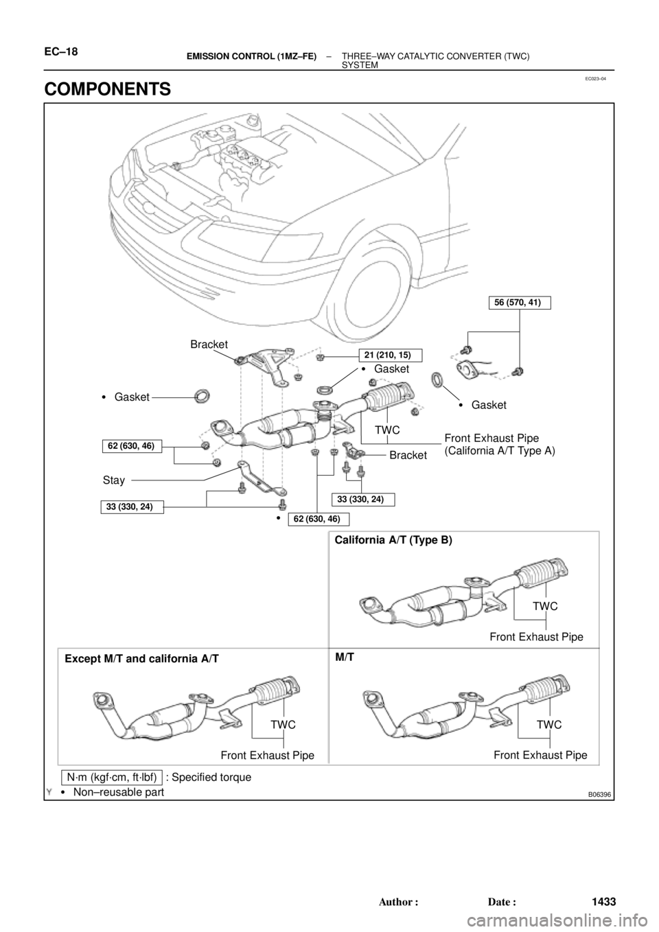
Except M/T and california A/TCalifornia A/T (Type B)
M/T
TWC
Front Exhaust Pipe
N´m (kgf´cm, ft´lbf) : Specified torque
� Non±reusable part
TWC
Front Exhaust Pipe
Bracket
� Gasket
Stay
62 (630, 46)
56 (570, 41)
TWC
Front Exhaust Pipe
(California A/T Type A)� Gasket � Gasket
�
62 (630, 46)
33 (330, 24)33 (330, 24)
Bracket
TWC
Front Exhaust Pipe
21 (210, 15)
EC±18± EMISSION CONTROL (1MZ±FE)THREE±WAY CATALYTIC CONVERTER (TWC)
SYSTEM
1433 Author�: Date�:
COMPONENTS
Page 2698 of 4592

(c)
A01808
± ENGINE MECHANICAL (1MZ±FE)CYLINDER HEAD
EM±33
1319 Author�: Date�:
(t) Disconnect the engine wire clamp")
S04790
Chamber Stay
Engine
HangerEGR
Pipe
S04791
8 mm Hexagon
Wrench
A01807
(b)
(c)
A01808
± ENGINE MECHANICAL (1MZ±FE)CYLINDER HEAD
EM±33
1319 Author�: Date�:
(t) Disconnect the engine wire clamp from the emission con-
trol valve set.
(u) Remove the 2 bolts and No.1 engine hanger.
(v) Remove the 2 bolts and air intake chamber stay.
(w) Remove the 4 nuts, No.2 EGR pipe and 2 gaskets.
(x) Using an 8 mm hexagon wrench, remove the 2 bolts, 2
nuts, the air intake chamber assembly and gasket.
9. REMOVE INTAKE MANIFOLD ASSEMBLY
(a) Disconnect the 6 injector connectors.
(b) Disconnect the fuel inlet hose from the fuel filter.
CAUTION:
Perform connecting operations of the fuel tube connector
(quick type) after observing the precautions.
(See page SF±1)
(c) Disconnect the heater hose from the intake manifold.
(d) Remove the 9 bolts, 2 nuts, 2 plate washers, the intake
manifold, delivery pipes and injectors assembly.
NOTICE:
�Be careful not to drop the injectors when removing
the delivery pipes.
�Pay attention to put any hung load on the injector to
and from the side direction.
Page 2732 of 4592
CYLINDER HEAD
EM±67
1353 Author�: Date�:
(b) Connect the fuel inlet hose to the fuel filter.
CAUTI")
S04791
8 mm Hexagon
Wrench
S04790
Chamber Stay
Engine
Hanger EGR
Pipe
± ENGINE MECHANICAL (1MZ±FE)CYLINDER HEAD
EM±67
1353 Author�: Date�:
(b) Connect the fuel inlet hose to the fuel filter.
CAUTION:
Perform connecting operations of the fuel tube connector
(quick type) after observing the precaution.
(See page SF±1)
(c) Connect the heater hose to the intake manifold.
29. RETIGHTEN WATER OUTLET MOUNTING BOLTS
AND NUTS
Tighten the 2 bolts and 2 nuts.
Torque: 15 N´m (150 kgf´cm, 11 ft´lbf)
30. INSTALL AIR INTAKE CHAMBER ASSEMBLY
(a) Using an 8 mm hexagon wrench, install a new gasket and
the air intake chamber assembly with the 2 bolts and 2
nuts. Uniformly tighten the bolts and nuts in several
passes.
Torque: 43 N´m (440 kgf´cm, 32 ft´lbf)
(b) Install 2 new gaskets and No.2 EGR pipe with the 4 nuts.
Torque: 12 N´m (120 kgf´cm, 9 ft´lbf)
(c) Install the No.1 engine hanger with the 2 bolts.
Torque: 39 N´m (400 kgf´cm, 29 ft´lbf)
(d) Install the air intake chamber stay with the 2 bolts.
Torque: 19.5 N´m (200 kgf´cm, 14 ft´lbf)
(e) Connect the PCV hose to the PCV valve on the RH cylin-
der head.
(f) Connect the ground strap and cable to the intake air con-
trol valve for the ACIS.
(g) Connect the ground cable and strap with the nut.
Torque: 14.5 N´m (145 kgf´cm, 10 ft´lbf)
(h) Connect the ground cable to the air intake chamber.
(i) Connect the brake booster vacuum hose to the air intake
chamber.
(j) Connect the 2 water bypass hoses to the throttle body.
(k) Connect the air assist hose to the throttle body.
(l) Connect the purge hose to the emission control valve set.
(m) Connect the 2 vacuum hoses to the vacuum tank for the
ACIS.
(n) Connect the engine wire clamp to the emission control
valve set.
(o) Install the PS pressure tube with the 2 nuts.
(p) Connect the throttle position sensor connector.
(q) Connect the IAC valve connector.
(r) Connect the EGR gas temperature sensor connector.
(s) Connect the EGR valve position sensor connector.
(t) Connect the VSV connector for the ACIS.
(u) Connect the VSV connecter for the EVAP.
(v) Connect the VSV connector for the EGR.
Page 2744 of 4592
ENGINE UNIT
EM±79
1365 Author�: Date�:
(f) Connect the 2 ground strap connectors to the LH fender
apron.
(g) Connect the DLC1 to the RH fender apron.
(h) Connect")
S05048
± ENGINE MECHANICAL (1MZ±FE)ENGINE UNIT
EM±79
1365 Author�: Date�:
(f) Connect the 2 ground strap connectors to the LH fender
apron.
(g) Connect the DLC1 to the RH fender apron.
(h) Connect the ground cable to the battery body bracket.
(i) Connect the engine wire protector clamp to the battery
body bracket.
(j) Connect the engine wire clamp to the bracket on the RH
fender apron.
(k) Connect the engine wire clamp to the bracket on the fuel
filter.
(l) Connect the brake booster vacuum hose to the air intake
chamber.
(m) Connect the engine coolant reservoir hose to the water
outlet.
(n) Connect the heater hose to the intake manifold.
(o) Connect the heater hose to the water inlet housing.
(p) Connect the fuel inlet hose to the fuel filter.
CAUTION:
Perform connecting operations of the fuel tube connector
(quick type) after observing the precautions.
(See page SF±6)
(q) Connect the purge hose to the pipe on the emission con-
trol valve set.
(r) Connect the 2 vacuum hoses to the vacuum tank for the
ACIS.
21. INSTALL FRONT EXHAUST PIPE
(a) Temporarily install 3 new gaskets and the front exhaust
pipe with the 2 bolts and 6 nuts.
(b) Tighten the 4 nuts holding the exhaust manifolds to the
front exhaust pipe.
Torque: 62 N´m (630 kgf´cm, 46 ft´lbf)
(c) Tighten the 2 bolts and 2 nuts holding the front exhaust
pipe to the center exhaust pipe.
Torque: 56 N´m (570 kgf´cm, 41 ft´lbf)
(d) Install the bracket with the 2 bolts.
Torque: 33 N´m (330 kgf´cm, 24 ft´lbf)
(e) Install the support stay with the 2 bolts.
Torque: 33 N´m (330 kgf´cm, 24 ft´lbf)
22. INSTALL RADIATOR (See page CO±24)
23. INSTALL CRUISE CONTROL ACTUATOR
24. INSTALL AIR CLEANER CAP ASSEMBLY AND AIR
CLEANER CASE
25. CONNECT ACCELERATOR CABLE
26. INSTALL ENGINE FENDER APRON SEALS
27. INSTALL BATTERY TRAY AND BATTERY
Page 2776 of 4592
EM0YU±01
A06653
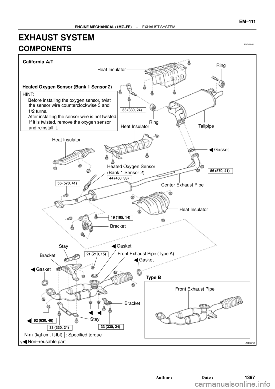
� Gasket
� Non±reusable part
N´m (kgf´cm, ft´lbf) : Specified torque� Gasket
�
�
�BracketFront Exhaust Pipe Bracket
StayHeat Insulator Center Exhaust Pipe� Gasket Heat InsulatorHeat Insulator
Heated Oxygen Sensor
(Bank 1 Sensor 2)TailpipeRing
Ring
33 (330, 24)
Heat Insulator
Heated Oxygen Sensor (Bank 1 Sensor 2)
� Before installing the oxygen sensor, twist
the sensor wire counterclockwise 3 and
1/2 turns.
If it is twisted, remove the oxygen sensor
and reinstall it. � After installing the sensor wire is not twisted. California A/T
Bracket
HINT:
56 (570, 41)
19 (195, 14)
21 (210, 15)
62 (630, 46)
33 (330, 24)33 (330, 24)
56 (570, 41)
Stay
Front Exhaust Pipe (Type A)
Type B
44 (450, 33)
� Gasket
± ENGINE MECHANICAL (1MZ±FE)EXHAUST SYSTEM
EM±111
1397 Author�: Date�:
EXHAUST SYSTEM
COMPONENTS
Page 2922 of 4592
OIL PUMP
LU±17
1681 Author�: Date�:
(b) Appl")
B04402
A Region ºXºRegion ºYº
A
CB B
C
Seal Width
Type A: 4 ± 5 mm
Type B: 3 ± 4 mmRegion ºXºRegion ºYº
AC Type A
Type B
± LUBRICATION (1MZ±FE)OIL PUMP
LU±17
1681 Author�: Date�:
(b) Apply seal packing to the oil pan as shown in the illustra-
tion.
Seal packing: Part No. 08826±00080 or equivalent
Region ºXº is at the outer side of the bolt hole.
Region ºYº is at the inner side of the bolt hole.
�Install a nozzle that has been cut to a 4 ± 5 mm (0.16
± 0.20 in.) (Type A) or 3 ± 4 mm (0.12 ± 0.16 in.)
(Type B) opening.
HINT:
Avoid applying an excessive amount to the surface.
�Parts must be assembled within 3 minutes of ap-
plication. Otherwise the material must be removed
and reapplied.
�Immediately remove nozzle from the tube and rein-
stall cap.
(c) Install the oil pan with the 19 bolts (or 17 bolts and 2 nuts).
Uniformly tighten the bolts and nuts in several passes.
Torque:
10 mm head: 8 N´m (80 kgf´cm, 69 in.´lbf)
12 mm head: 19.5 N´m (200 kgf´cm, 14 ft´lbf)
14 mm head: 37.2 N´m (380 kgf´cm, 27 ft´lbf)
(d) Install the flywheel housing under cover and exhaust pipe
support stay with the 2 bolts.
Torque: 7.8 N´m (80 kgf´cm, 69 in.´lbf)
5. INSTALL OIL STRAINER
Install a new gasket and the oil strainer with the bolt and 2 nuts.
Torque: 8 N´m (80 kgf´cm, 69 in.´lbf)
6. INSTALL NO.2 OIL PAN
(a) Remove any old packing (FIPG) material and be careful
not to drop any oil on the contact surface of the No.1 and
No.2 oil pans.
�Using a razor blade and gasket scraper, remove all
the old packing (FIPG) material from the gasket sur-
faces and sealing grooves.
�Thoroughly clean all components to remove all the
loose material.
�Using a non±residue solvent, clean both sealing
surfaces.
NOTICE:
Do not use a solvent which will affect the painted surfaces.
Page 3326 of 4592
SFI SYSTEM
1437 Author�:")
Z11336
California
Except CaliforniaGrommetInsulator O±Ring
InjectorO±Ring
O±Ring
Grommet
InjectorInsulator
S04583
Pull
S05040
Vinyl Bag
S05382
Retainer
SF±4
± SFI (5S±FE)SFI SYSTEM
1437 Author�: Date�:
(e) Install the injector to the delivery pipe and cylinder head,
as shown in the illustration.
Before installing the injector, must apply spindle oil or gas-
oline on the place where a delivery pipe or an intake man-
ifold touches an O±ring of the injector.
(f) Observe these precautions when disconnecting the fuel
tube connector (quick type):
(1) Check if there is any dirt like mud on the pipe and
around the connector before disconnecting them
and clean the dirt away.
(2) Be sure to disconnect with hands.
(3) When the connector and the pipe are stuck, pinch
the retainer between the hands, push and pull the
connector to free to disconnect and pull it out. Do
not use any tool at this time.
(4) Inspect if there is any dirt or the likes on the seal sur-
face of the disconnected pipe and clean it away.
(5) Prevent the disconnected pipe and connector from
damaging and mixing foreign objects by covering
them with a vinyl bag.
(g) Observe these precautions when connecting the fuel
tube connector (quick type):
(1) Do not reuse the retainer removed from the pipe.
(2) Must use hands without using tools when to remove
the retainer from the pipe.
(3) Check if there is any damage or foreign objects on
the connected part of the pipe.
Page 3331 of 4592
SF0D8±02
Z19025
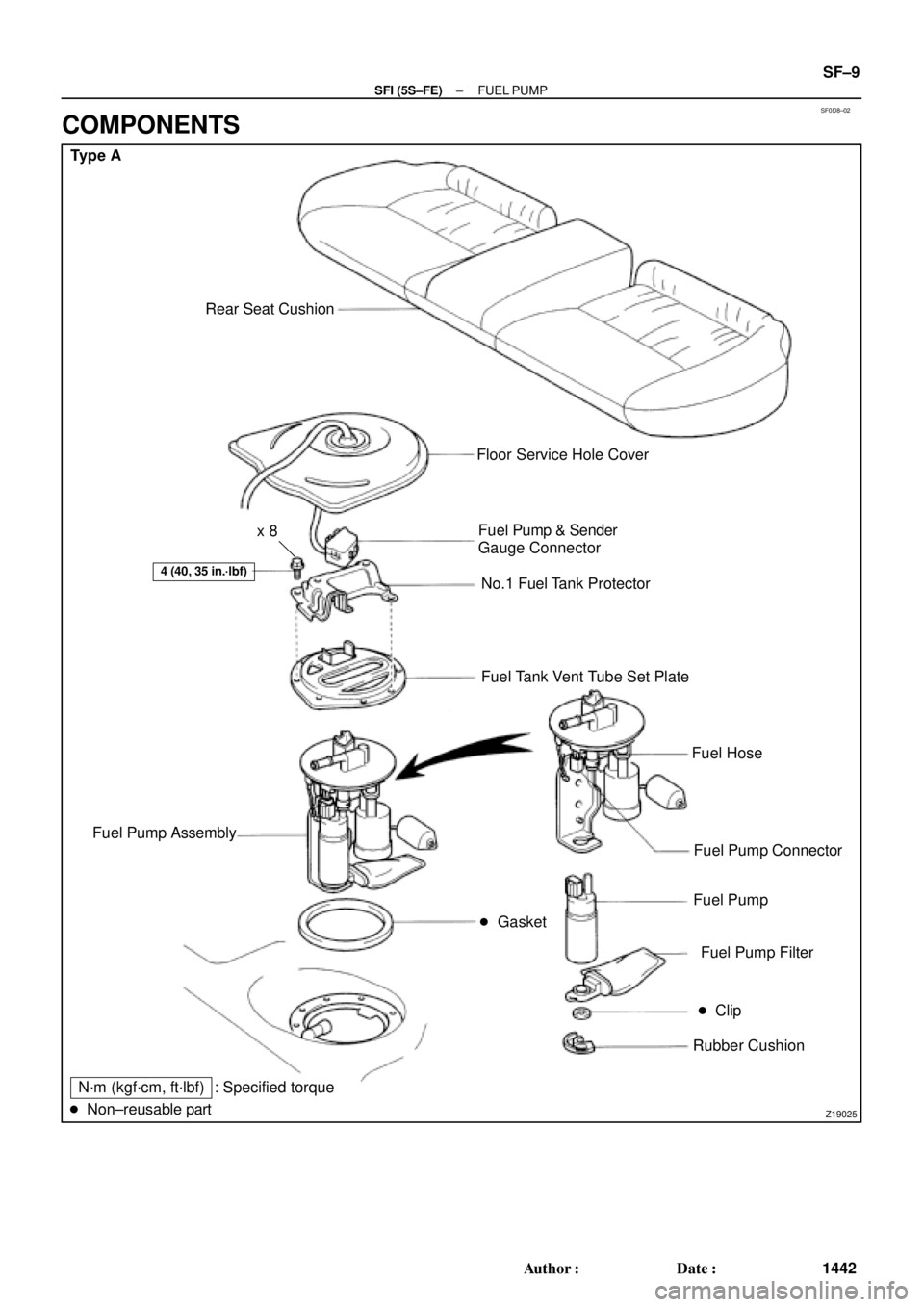
Type A
Rear Seat Cushion
� Gasket
4 (40, 35 in.´lbf)
Floor Service Hole Cover
Fuel Pump & Sender
Gauge Connector
No.1 Fuel Tank Protector
Fuel Tank Vent Tube Set Plate
Fuel Hose
Fuel Pump Connector
Fuel Pump
Fuel Pump Filter
� Clip
Rubber Cushion Fuel Pump Assembly
N´m (kgf´cm, ft´lbf)
� Non±reusable part: Specified torquex 8
± SFI (5S±FE)FUEL PUMP
SF±9
1442 Author�: Date�:
COMPONENTS