Page 856 of 4592

(b)(a)
BO±12
± BODYFRONT DOOR
2360 Author�: Date�:
DISASSEMBLY
1. w/o Power Window:
REMOVE REGULATOR HANDLE
Pull off the snap ring with a shop rag an")
BO0L3±01
H01738
N20968
N210034 Clips
N20969
(c)
(b)(a)
BO±12
± BODYFRONT DOOR
2360 Author�: Date�:
DISASSEMBLY
1. w/o Power Window:
REMOVE REGULATOR HANDLE
Pull off the snap ring with a shop rag and remove the regulator
handle and plate.
HINT:
At the time of assembly, please refer to the following item.
With the door window fully closed, install the plate and the regu-
lator handle with the snap ring.
2. REMOVE INSIDE HANDLE BEZEL
(a) Using a screwdriver, pry open the screw cover and re-
move the screw.
HINT:
Tape the screwdriver tip before use.
(b) Using a screwdriver, pry out the bezel.
HINT:
Tape the screwdriver tip before use.
3. REMOVE FRONT WINDOW UPPER GARNISH
4. REMOVE DOOR TRIM
(a) Using a screwdriver, remove the screw caps.
HINT:
Tape the screwdriver tip before use.
(b) Remove the 2 clips, 2 screws and 2 bolts.
(c) Insert a screwdriver between the door and door trim to pry
out.
(d) Pull the trim upward to remove it, then remove the power
window switch and disconnect the harness connector.
5. REMOVE THESE PARTS:
(a) Outside rear view mirror
Torque: 5.5 N´m (55 kgf´cm, 49 in.´lbf)
(b) Speaker
6. REMOVE DOOR INSIDE HANDLE
(a) Remove the screw and pull the handle forward.
Torque: 3.5 N´m (35 kgf´cm, 31 in.´lbf)
(b) Remove the link from the clamp.
(c) Remove the inside handle from the ends of the 2 links.
7. REMOVE SERVICE HOLE COVER
Remove the grommet, then remove the service hole cover.
Page 857 of 4592
N20970
(a)
(b)(b)
N21004
Clip
H01729
: 7 rivets
: clip
: clip
: clip
± BODYFRONT DOOR
BO±13
2361 Author�: Date�:
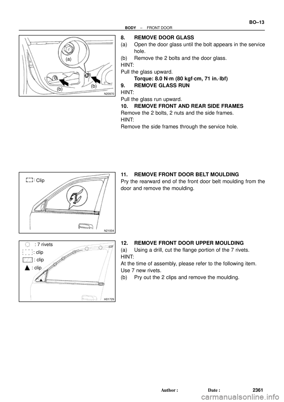
8. REMOVE DOOR GLASS
(a) Open the door glass until the bolt appears in the service
hole.
(b) Remove the 2 bolts and the door glass.
HINT:
Pull the glass upward.
Torque: 8.0 N´m (80 kgf´cm, 71 in.´lbf)
9. REMOVE GLASS RUN
HINT:
Pull the glass run upward.
10. REMOVE FRONT AND REAR SIDE FRAMES
Remove the 2 bolts, 2 nuts and the side frames.
HINT:
Remove the side frames through the service hole.
11. REMOVE FRONT DOOR BELT MOULDING
Pry the rearward end of the front door belt moulding from the
door and remove the moulding.
12. REMOVE FRONT DOOR UPPER MOULDING
(a) Using a drill, cut the flange portion of the 7 rivets.
HINT:
At the time of assembly, please refer to the following item.
Use 7 new rivets.
(b) Pry out the 2 clips and remove the moulding.
Page 858 of 4592

H01730
w/ Power Window:
w/o Power Window:
N20971
H01732
w/o Power Door Lock
w/ Power Door Lock BO±14
± BODYFRONT DOOR
2362 Author�: Date�:
13. REMOVE WINDOW REGULATOR ASSEMBLY
Remove the bolts and window regulator.
Torque: 5.5 N´m (55 kgf´cm, 49 in.´lbf)
HINT:
At the time of reassembly, please refer to the following item.
Apply MP grease to the window regulator rollers.
14. w/ Power Window:
REMOVE MOTOR FROM WINDOW REGULATOR
Remove the 3 screws and motor.
15. REMOVE DOOR LOCK
(a) Remove the 2 clips.
(b) Disconnect the 2 links from the door lock and remove the
links.
(c) Disconnect the 2 links from the outside handle and the
lock cylinder.
(d) Remove the 3 screws and door lock.
HINT:
At the time of reassembly, please refer to the following item.
Apply adhesive to 3 screws.
Part No. 08833±00070, THREE BOND 1324 or equiva-
lent
Torque: 5.0 N´m (50 kgf´cm, 43 in.´lbf)
(e) w/ Power Door Lock:
Disconnect the connector.
(f) Remove the door lock through the service hole.
HINT:
At the time of reassembly, please refer to the following item.
Apply MP grease to the sliding surface of the door lock.
16. REMOVE OUTSIDE HANDLE
Torque: 7.0 N´m (70 kgf´cm, 61 in.´lbf)
Page 859 of 4592
BO0L4±01
N20966SST
N20967
BO2556
± BODYFRONT DOOR
BO±15
2363 Author�: Date�:
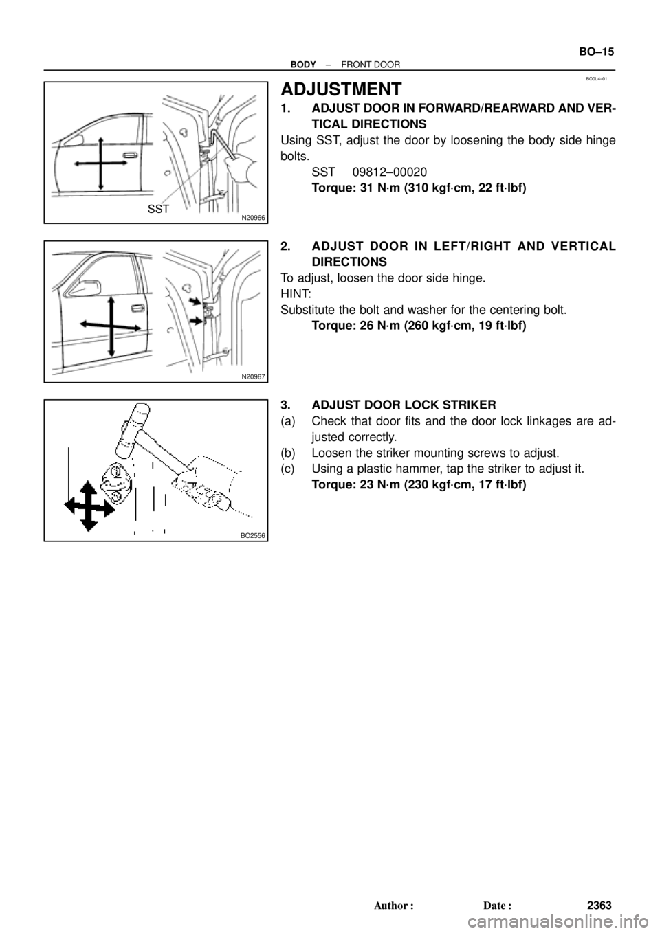
ADJUSTMENT
1. ADJUST DOOR IN FORWARD/REARWARD AND VER-
TICAL DIRECTIONS
Using SST, adjust the door by loosening the body side hinge
bolts.
SST 09812±00020
Torque: 31 N´m (310 kgf´cm, 22 ft´lbf)
2. ADJUST DOOR IN LEFT/RIGHT AND VERTICAL
DIRECTIONS
To adjust, loosen the door side hinge.
HINT:
Substitute the bolt and washer for the centering bolt.
Torque: 26 N´m (260 kgf´cm, 19 ft´lbf)
3. ADJUST DOOR LOCK STRIKER
(a) Check that door fits and the door lock linkages are ad-
justed correctly.
(b) Loosen the striker mounting screws to adjust.
(c) Using a plastic hammer, tap the striker to adjust it.
Torque: 23 N´m (230 kgf´cm, 17 ft´lbf)
Page 861 of 4592
BO0L6±01
H01733
Door LockRear Door Upper
Moulding
Door Belt Moulding
Door Glass
Outside handle
Door Glass Run
Door Lock
Door Lock Striker
Rear Side Frame
Rear Door WeatherstripWindow Regulator
Inside Handle BezelInside HandleWindow
Regulator
Motor Child Protector
Lock Lever Cover
Snap Ring
Regulator
Handle Plate Door Trim Service Hole Cover Power Window
Switch Cover Door HingeDoor Hinge
Door Check w/o Power Door
Lock:
w/o Power Window:
: Specified torque
N´m (kgf´cm, ft´lbf)
3.5 (35, 31 in.´lbf)
5.5 (55, 49 in.´lbf)
5.5 (55, 49 in.´lbf)
23 (230, 17)
7.0 (70, 61 in.´lbf)
Door Lock Control Link
Door Lock Remote
Control Link
5.0 (50, 43 in.´lbf)
8.0 (80, 71 in.´lbf)
26 (260, 19)
8.0 (80, 71 in.´lbf)
30 (300, 22)
26 (260, 19)
± BODYREAR DOOR
BO±17
2365 Author�: Date�:
REAR DOOR
COMPONENTS
Page 862 of 4592

H01738
BO0L8±01
N20968
N210076 Clips
N20969
BO±18
± BODYREAR DOOR
2366 Author�: Date�:
DISASSEMBLY
1. w/o Power Window:
REMOVE REGULATOR HANDLE
Pull off the snap ring with a shop rag and remove the regulator
handle and plate.
HINT:
At the time of reassembly, please refer to the following item.
With the door window fully closed, install the plate and the regu-
lator handle with the snap ring.
2. w/ Power Window:
REMOVE POWER WINDOW SWITCH
Using a screwdriver, pry out the switch, then disconnect the
connector.
HINT:
Tape the screwdriver tip before use.
3. REMOVE INSIDE HANDLE BEZEL
(a) Using a screwdriver, pry open the screw cover and re-
move the screw.
HINT:
Tape the screwdriver tip before use.
(b) Using a screwdriver, pry out the bezel.
HINT:
Tape the screwdriver tip before using. Use the screwdriver to re-
lease the bezel from the top and bottom protrusions on the han-
dle assembly as shown.
4. REMOVE DOOR TRIM
HINT:
Tape a screwdriver tip before use.
(a) Using the screwdriver, remove the 2 screw caps.
(b) Remove the inside cover.
(c) Remove the 2 screws and clip.
(d) Insert the screwdriver between the door and door trim to
pry out.
(e) Pull the trim upward to remove it, then disconnect the con-
nector.
5. REMOVE DOOR INSIDE HANDLE
(a) Remove the screw and pull the handle forward.
Torque: 3.5 N´m (35 kgf´cm, 31 in.´lbf)
(b) Remove the link from the clamp.
(c) Remove the inside handle from the ends of the 2 links.
6. REMOVE SERVICE HOLE COVER
Remove the grommet, then remove the service hole cover.
Page 863 of 4592
N20974
(b)(b)
(a)
N21008
Clip
H01743
: 7 rivets
: clips
: clips
: clips
± BODYREAR DOOR
BO±19
2367 Author�: Date�:
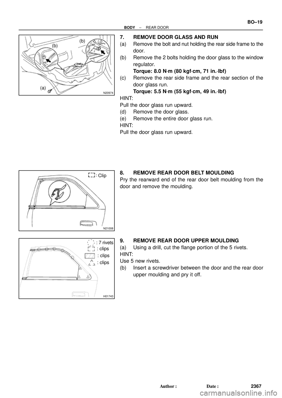
7. REMOVE DOOR GLASS AND RUN
(a) Remove the bolt and nut holding the rear side frame to the
door.
(b) Remove the 2 bolts holding the door glass to the window
regulator.
Torque: 8.0 N´m (80 kgf´cm, 71 in.´lbf)
(c) Remove the rear side frame and the rear section of the
door glass run.
Torque: 5.5 N´m (55 kgf´cm, 49 in.´lbf)
HINT:
Pull the door glass run upward.
(d) Remove the door glass.
(e) Remove the entire door glass run.
HINT:
Pull the door glass run upward.
8. REMOVE REAR DOOR BELT MOULDING
Pry the rearward end of the rear door belt moulding from the
door and remove the moulding.
9. REMOVE REAR DOOR UPPER MOULDING
(a) Using a drill, cut the flange portion of the 5 rivets.
HINT:
Use 5 new rivets.
(b) Insert a screwdriver between the door and the rear door
upper moulding and pry it off.
Page 864 of 4592

(b)(a )
H01746
w/o Power Door Lock
w/ Power Door Lock BO±20
± BODYREAR DOOR
2368 Author�: Date�:
10. REMOVE WINDOW REGULATOR ASSEMBLY
Remove the")
H01744
w/ Power Window:
w/o Power Window:
N20975
(b)
(b)(a )
H01746
w/o Power Door Lock
w/ Power Door Lock BO±20
± BODYREAR DOOR
2368 Author�: Date�:
10. REMOVE WINDOW REGULATOR ASSEMBLY
Remove the bolts and window regulator assembly.
Torque: 5.5 N´m (55 kgf´cm,49 in.´lbf)
HINT:
At the time of reassembly, please refer to the following item.
Apply MP grease to the window regulator rollers.
11. w/ Power Window:
REMOVE MOTOR FROM WINDOW REGULATOR
Remove the 3 screws and motor.
12. REMOVE REAR DOOR LOCK CHILD PROTECTION
COVER
Using a screwdriver, pry out the cover.
HINT:
Tape the screwdriver tip before use.
13. REMOVE DOOR LOCK
(a) Remove the clip.
(b) Disconnect the 2 links from the door lock and remove the
2 links.
(c) Disconnect the link from the outside handle.
(d) Remove the 3 screws.
Torque: 5.0 N´m (50 kgf´cm, 43 in.´lbf)
HINT:
At the time of reassembly, please refer to the following item.
Apply adhesive to the 3 screws.
Part No. 08833±00070, THREE BOND 1324 or equiva-
lent
(e) w/ Power Door Lock:
Disconnect the connector.
(f) Remove the door lock through the service hole.
HINT:
At the time of reassembly, please refer to the following item.
Apply MP grease to the sliding surface of the door lock.
14. REMOVE OUTSIDE HANDLE
Torque: 7.0 N´m (70 kgf´cm, 61 in.´lbf)