Page 865 of 4592
 Remove the front part of t")
BO0L7±01
N21006
3 Clips
2 Clips
N20972
N20973
BO2556
± BODYREAR DOOR
BO±21
2369 Author�: Date�:
ADJUSTMENT
1. ADJUST DOOR IN FORWARD/REARWARD AND VER-
TICAL DIRECTION
(a) Remove the front part of the rear seat side garnish.
(b) Remove the rear part of the front door inside scuff plate.
(c) Remove the center pillar lower garnish.
HINT:
Pull both sides of the top and bottom part of the garnish out-
ward, then pull out to remove the garnish.
(d) Loosen the body side hinge nuts to adjust.
Torque: 26 N´m (260 kgf´cm, 19 ft´lbf)
(e) Install center pillar lower garnish.
(f) Install front door inside scuff plate.
(g) Install rear seat side garnish.
2. ADJUST DOOR IN LEFT/RIGHT AND VERTICAL
DIRECTIONS
Loosen the door side hinge bolts to adjust.
HINT:
Substitute a bolt with washer for the centering bolt.
Torque: 26 N´m (260 kgf´cm, 19 ft´lbf)
3. ADJUST DOOR LOCK STRIKER
(a) Check that the door fit and door lock linkages are adjusted
correctly.
(b) Loosen the striker mounting screws to adjust.
Torque: 23 N´m (230 kgf´cm, 17 ft´lbf)
(c) Using a plastic hammer, tap the striker to adjust it.
Page 867 of 4592
BO0LA±01
H01758
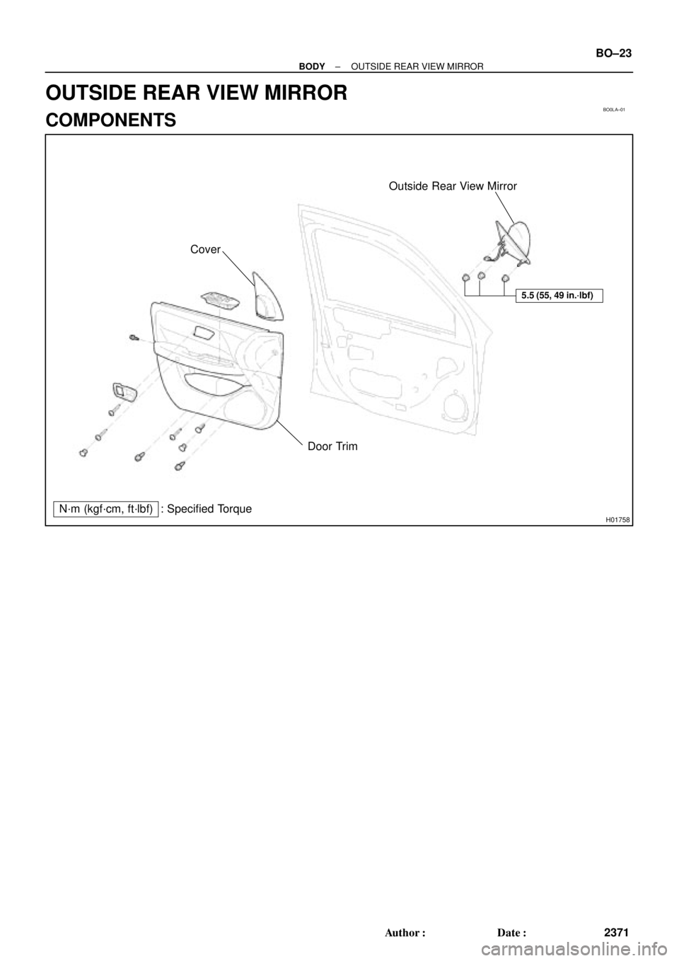
Outside Rear View Mirror
Cover
Door Trim
N´m (kgf´cm, ft´lbf) : Specified Torque
5.5 (55, 49 in.´lbf)
± BODYOUTSIDE REAR VIEW MIRROR
BO±23
2371 Author�: Date�:
OUTSIDE REAR VIEW MIRROR
COMPONENTS
Page 871 of 4592
BO0LD±01
H01747
Torsion Bar
Luggage Compart-
ment Door Hinge
Luggage Compart-
ment Door Hinge
Luggage Compartment
Door
Luggage Compartment
Door Trim
Left Side Luggage
Trim
Finish Side Trim
Rear Luggage Trim
Rear Seat CushionRoom Partition TrimPackage Tray Trim
High Mounted
Stop Light
Rear SeatbackFinish Side Trim Door Lock
Door Lock StrikerLeft Hand Back
Up LightRight Hand
Back Up Light Right Side Luggage
Trim
: Specified torque
N´m (kgf´cm, ft´lbf)
Lock Cylinder
Luggage Compart-
ment Floor Mat
8.0 (80, 71 in.´lbf)
8.0 (80, 71 in.´lbf)
5.5 (55, 49 in.´lbf)
5.5 (55, 49 in.´lbf)
± BODYLUGGAGE COMPARTMENT DOOR AND HINGE
BO±27
2375 Author�: Date�:
LUGGAGE COMPARTMENT DOOR AND HINGE
COMPONENTS
Page 872 of 4592

BO0LE±01
N22588
121
N21430
: 4 Clips
N22591
BO±28
± BODYLUGGAGE COMPARTMENT DOOR AND HINGE
2376 Author�: Date�:
REMOVAL
1. REMOVE LUGGAGE COMPARTMENT DOOR TRIM
2. REMOVE LUGGAGE COMPARTMENT DOOR
(a) Disconnect the connector.
(b) Using a clip remover, disconnect the clamps.
(c) Remove the 4 bolts and door.
Torque: 8.0 N´m (80 kgf´cm, 71 in.´lbf)
3. REMOVE THESE PARTS:
(a) Luggage compartment floor mat
(b) LH and RH rear floor finish side plates
(c) Inner cover trims
(d) Rear seat
(e) Room partition trims
4. REMOVE HIGH±MOUNTED STOP LIGHT
(a) Push on the both side of the cover to release the claws by
your hand and remove the cover as shown in the illustra-
tion.
(b) Remove the 2 bolts and stop light, then disconnect the
connector.
5. REMOVE ROOF SIDE INNER GARNISH
(a) Remove the clip.
(b) Using a screwdriver, pry loose and remove the garnish.
HINT:
Tape the screwdriver tip before use.
6. REMOVE PACKAGE TRAY TRIM
7. REMOVE TORSION BAR
(a) Remove the torsion bar from the center bracket.
Page 874 of 4592
BO0LF±01
BO±30
± BODYLUGGAGE COMPARTMENT DOOR AND HINGE
2378 Author�: Date�:
DISASSEMBLY
1. REMOVE DOOR LOCK
(a) Disconnect the control link.
(b) Remove the 2 bolts and lock.
Torque: 5.5 N´m (56 kgf´cm, 49 in.´lbf)
2. REMOVE REAR COMBINATION LIGHT
(a) Disconnect the connector.
(b) Remove the 10 nuts and rear combination lights.
Page 875 of 4592
BO0LG±01
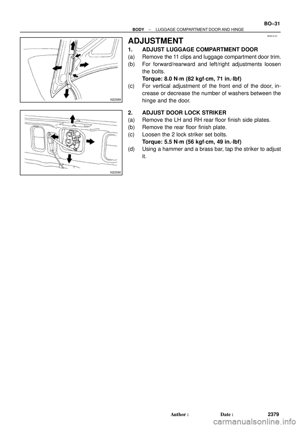
N22589
N22590
± BODYLUGGAGE COMPARTMENT DOOR AND HINGE
BO±31
2379 Author�: Date�:
ADJUSTMENT
1. ADJUST LUGGAGE COMPARTMENT DOOR
(a) Remove the 11 clips and luggage compartment door trim.
(b) For forward/rearward and left/right adjustments loosen
the bolts.
Torque: 8.0 N´m (82 kgf´cm, 71 in.´lbf)
(c) For vertical adjustment of the front end of the door, in-
crease or decrease the number of washers between the
hinge and the door.
2. ADJUST DOOR LOCK STRIKER
(a) Remove the LH and RH rear floor finish side plates.
(b) Remove the rear floor finish plate.
(c) Loosen the 2 lock striker set bolts.
Torque: 5.5 N´m (56 kgf´cm, 49 in.´lbf)
(d) Using a hammer and a brass bar, tap the striker to adjust
it.
Page 879 of 4592
BO0LK±01
N21119
Wiper MotorCowl Louver RH
Cowl Louver LH
Wiper Motor
Assembly
Window
Washer Nozzle
N´m (kgf´cm, ft´lbf) : Specified torqueWeatherstripWiper
Arms
Wiper
Link
24 (245, 18)
5.5 (55, 49 in.´lbf)
± BODYFRONT WIPER AND WASHER
BO±35
2383 Author�: Date�:
FRONT WIPER AND WASHER
COMPONENTS
Page 882 of 4592
BO0LN±01
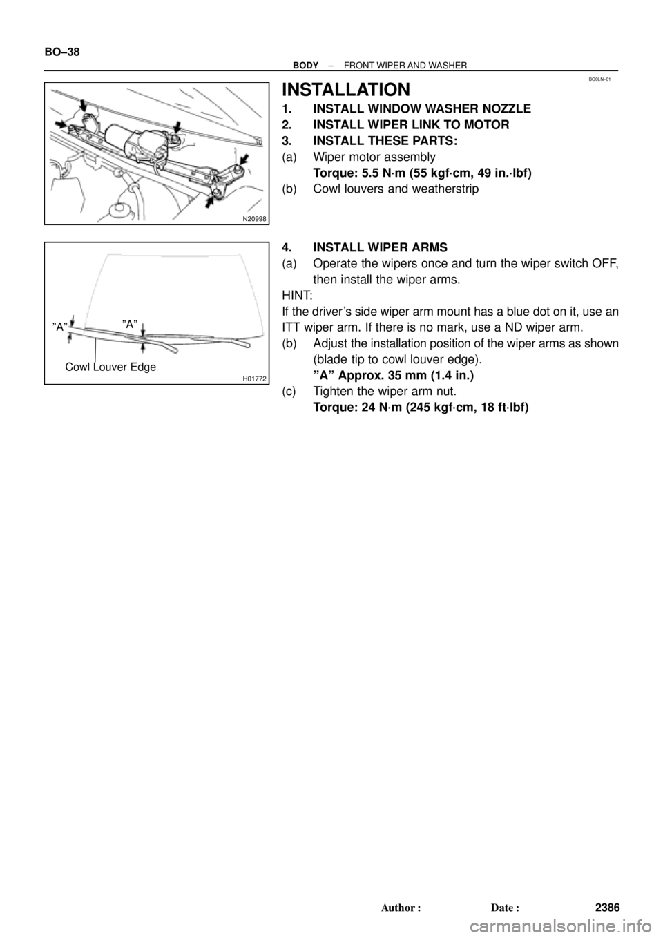
N20998
H01772
ºAººAº
Cowl Louver Edge
BO±38
± BODYFRONT WIPER AND WASHER
2386 Author�: Date�:
INSTALLATION
1. INSTALL WINDOW WASHER NOZZLE
2. INSTALL WIPER LINK TO MOTOR
3. INSTALL THESE PARTS:
(a) Wiper motor assembly
Torque: 5.5 N´m (55 kgf´cm, 49 in.´lbf)
(b) Cowl louvers and weatherstrip
4. INSTALL WIPER ARMS
(a) Operate the wipers once and turn the wiper switch OFF,
then install the wiper arms.
HINT:
If the driver's side wiper arm mount has a blue dot on it, use an
ITT wiper arm. If there is no mark, use a ND wiper arm.
(b) Adjust the installation position of the wiper arms as shown
(blade tip to cowl louver edge).
ºAº Approx. 35 mm (1.4 in.)
(c) Tighten the wiper arm nut.
Torque: 24 N´m (245 kgf´cm, 18 ft´lbf)


 : Specified torqueWeatherstripWiper
Arms
Wiper
Link
24 (245, 18)
5.5 (55, 49")