Page 916 of 4592

BO0MB±01
N20950
Instrument Panel ReinforcementNN
DD
No.2 Instrumental Panel Bracket
No.1 Instrumental Panel Bracket
No.2 Instrumental Panel Brace
QQH N
N
N
N
GG
NG
NOB
NN
Instrument Panel Brace Mount
No.1 Instrument
Panel BraceFront Pillar Garnish
Front Pillar
GarnishFront
Passenger
Airbag
Assembly
20 (200, 14)
No.2 Side Defroster Nozzle
Cowl Side Trim
Front Door Openin
g
Cover
Instrument Panel
C
Remote Control
Mirror Hole Base
Upper Column
CoverHazard Warning
Switch
Lower Finish
PlateGlove Compartment
Door Finish PlateFront Door
Inside Scuff Plate
FFF
FJ
Glove
Compartment
No.2 Lower
Panel A
A
Cluster Finish
Panel
Lower Column
Cover
Front Door
Opening
Cover
Cowl Side
TrimD
DD
D
D
F
AA
Lower Panel
InsertCoin
BoxCombination SwitchCombination
MeterRadio Assembly
Center Cluster
Finish Panel
A/C
Control Assembly
35 (360, 26)
Steering
Wheel
Pad Steering Wheel No.1 Lower
Panel
Front Door
Inside Scuff PlateFront Console
Box
Center Console
Upper PanelF
F
B
B
Rear Console
Box
N´m (kgf´cm, ft´lbf) : Specified torque BO±72
± BODYINSTRUMENT PANEL
2420 Author�: Date�:
INSTRUMENT PANEL
COMPONENTS
Page 921 of 4592

Remove the 2 bolts, 4 nuts and the front passenger airbag a")
W03509
N20991
N20992
N20993
± BODYINSTRUMENT PANEL
BO±77
2425 Author�: Date�:
19. REMOVE FRONT PASSENGER AIRBAG ASSEMBLY
(See page RS±28)
Remove the 2 bolts, 4 nuts and the front passenger airbag as-
sembly.
Torque:
Bolt: 20 N´m (200 kgf´cm, 14 ft´lbf)
CAUTION:
�Store the front passenger airbag door facing upward
(never downward).
�Never disassemble the front passenger airbag as-
sembly.
NOTICE:
The 2 bolts to the instrument panel have been anti±rust
treated. After removing the front passenger airbag assem-
bly, always replace the bolts and nuts with new ones.
20. REMOVE No.1 AND No.2 INSTRUMENT PANEL
BRACKETS
Remove the 4 bolts and the No.1 and No.2 panel brackets.
21. REMOVE NO.2 SIDE DEFROSTER NOZZLE
22. REMOVE INSTRUMENT PANEL ASSEMBLY
(a) Disconnect the connectors from the LH and RH connector
holders.
(b) Remove the bolts holding the ground wire to the body.
(c) Remove the connector holder from the body.
(d) Disconnect the connectors.
(e) Remove the bolt holding the ground wire to the No.2
instrument panel brace.
Page 926 of 4592
BO0MG±01
N22600
Assist Grip
Sun VisorRoof Headlining
Assist Grip
Room Light Map Light
Assembly
Holder
Cover
Holder
Sun Visor
Center Pillar Garnish
Roof Side Inner Garnish Front Pillar Garnish
Front Door Scuff
PlateLower Center
Pillar GarnishRear Side Seat
Back RH
42 (420, 31)
Rear Seat
Side GarnishRear Seatback
Rear Side Seat
Back LH
42 (420, 31)
18 (185, 13)
18 (185, 13)
18 (185, 13)
Rear Seat Cushion
Center Pillar Garnish
42 (420, 31)
42 (420, 31)
Roof Seat
Side Garnish
Front Pillar Garnish
Rear Seat
Side Garnish
Lower Center
Pillar Garnish
42 (420, 31)
Front Door Scuff
Plate
N´m (kgf´cm, ft´lbf): Specified torque BO±82
± BODYROOF HEADLINING
2430 Author�: Date�:
ROOF HEADLINING
COMPONENTS
Page 931 of 4592
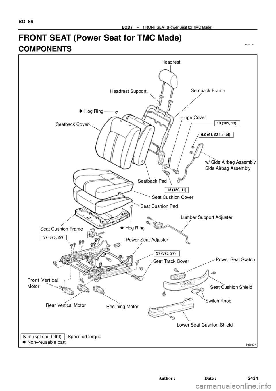
BO0MJ±01
H01977
Headrest
Seatback Frame
w/ Side Airbag Assembly
Side Airbag Assembly Headrest Support
� Hog Ring
Seatback Pad Seatback Cover
Seat Cushion Cover
Seat Cushion Pad
Seat Cushion Frame� Hog RingLumber Support Adjuster
Power Seat Adjuster
Seat Cushion Shield
Switch Knob Front Vertical
Motor
Lower Seat Cushion ShieldHinge Cover
Power Seat Switch
: Specified torque
N´m (kgf´cm, ft´lbf)
� Non±reusable part
37 (375, 27)
37 (375, 27)
Rear Vertical Motor
Seat Track Cover
Reclining Motor
15 (150, 11)
6.0 (61, 53 in.´lbf)
18 (185, 13)
BO±86
± BODYFRONT SEAT (Power Seat for TMC Made)
2434 Author�: Date�:
FRONT SEAT (Power Seat for TMC Made)
COMPONENTS
Page 935 of 4592

2438 Author�: Date�:
REASSEMBLY
1. INSTALL RECLINING MOTOR
Connect the No.2 drive cable, then install the reclining m")
BO0MM±01
H01980
H01979
H01978
BO±90
± BODYFRONT SEAT (Power Seat for TMC Made)
2438 Author�: Date�:
REASSEMBLY
1. INSTALL RECLINING MOTOR
Connect the No.2 drive cable, then install the reclining motor
with 2 screws.
2. INSTALL SLIDE MOTOR
Connect the No.1 drive cable, then install the slide motor with
2 screws.
3. INSTALL REAR VERTICAL MOTOR
Install the front vertical motor with 2 screws.
4. INSTALL LOWER SEAT CUSHION SHIELD
5. INSTALL SEAT CUSHION COVER
(a) Install the seat cushion cover with new hog rings to seat
cushion pad.
(b) Install the seat cushion cover with pad to the seat cushion
frame with hook and 2 clips.
HINT:
Install the hog rings to prevent wrinkles as least as possible.
6. INSTALL SEAT CUSHION ASSEMBLY
Install the seat cushion assembly with 4 bolts.
7. INSTALL SIDE AIRBAG ASSEMBLY
Install the side airbag assembly with 2 new nuts and 1 clip of
side airbag wire harness to the seatback frame.
Torque: 6.0 N´m (61 N´m, 53 in.´lbf)
NOTICE:
�Make sure that the side airbag assembly is installed
to the specified torque.
�If the side airbag assembly has been dropped, or
there are cracks, dents or other defects in the case or
connector, replace the side airbag assembly with a
new one.
8. INSTALL SEATBACK COVER
(a) Install the seatback cover with new hog rings to the seat-
back pad.
(b) Install the seatback cover with pad to the seatback frame
with new hog rings.
(c) Install the headrest supports.
Page 938 of 4592
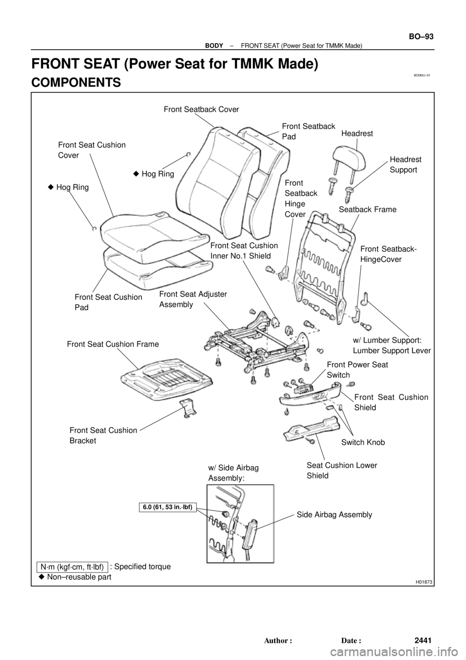
BO0MU±01
H01873
Front Seat Cushion
Cover
� Hog Ring
� Hog Ring
Front Seat Cushion
Pad
Front Seat Cushion Frame
Front Seat Adjuster
Assembly
Front Seat Cushion
Inner No.1 Shield
Front Seatback
PadHeadrest
Front
Seatback
Hinge
CoverHeadrest
Support
Seatback Frame
Front Seatback-
HingeCover
w/ Lumber Support:
Lumber Support Lever
Front Power Seat
Switch
Front Seat Cushion
Shield
Switch Knob
Seat Cushion Lower
Shield
Front Seat Cushion
Bracket
w/ Side Airbag
Assembly:
Side Airbag Assembly
6.0 (61, 53 in.´lbf)
N´m (kgf´cm, ft´lbf): Specified torque
� Non±reusable part
Front Seatback Cover
± BODYFRONT SEAT (Power Seat for TMMK Made)
BO±93
2441 Author�: Date�:
FRONT SEAT (Power Seat for TMMK Made)
COMPONENTS
Page 941 of 4592

2444 Author�: Date�:
REASSEMBLY
1. INSTALL THESE PARTS:
(a) Front seat cushion inner shield
(b) Front seat cushion bracket
(c) Fron")
BO0MX±01
H01870
BO±96
± BODYFRONT SEAT (Power Seat for TMMK Made)
2444 Author�: Date�:
REASSEMBLY
1. INSTALL THESE PARTS:
(a) Front seat cushion inner shield
(b) Front seat cushion bracket
(c) Front seat cushion inner No.1 shield
2. INSTALL SEAT CUSHION COVER
(a) Install the seat cushion cover to seat cushion pad.
(b) Install the seat cushion cover with pad to the seat cushion
frame.
3. INSTALL SEAT CUSHION ASSEMBLY
Install the seat cushion assembly with 4 bolts to the seat adjust-
er.
HINT:
Tighten the 4 bolts temporarily, then from the bolts on the rear
side tighten completely.
4. w/ Side Airbag Assembly:
INSTALL SIDE AIRBAG ASSEMBLY
Install the side airbag assembly with 2 nuts to the seatback
frame.
Torque: 6.0 N´m (61 kgf´cm, 53 in.´lbf)
NOTICE:
�Make sure that the side airbag assembly is installed
to the specified torque.
�If the side airbag assembly has been dropped, or
there are cracks, dents or other defects in the case or
connector, replace the side airbag assembly with a
new one.
�When installing the side airbag assembly, take care
is not pinched between other parts.
5. INSTALL SEATBACK COVER
(a) Install the seatback cover to the seatback pad.
(b) Install the seatback cover with pad to the seatback frame.
(c) Install the headrest supports.
(d) w/ Side Airbag Assembly:
Hang the hook on to the seatback frame.
CAUTION:
Take care to hung the hook securely. Otherwise the seat
cove slides, it might cause incorrect deploying.
Page 944 of 4592
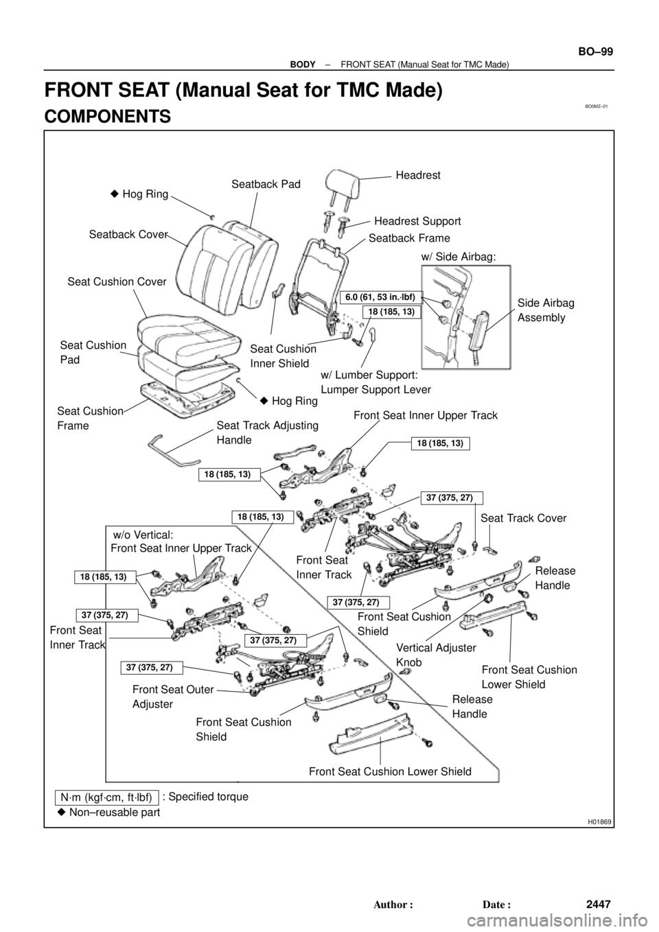
BO0MZ±01
H01869
� Hog RingSeatback PadHeadrest
Seatback Cover
Headrest Support
Seat Cushion Cover
Seatback Frame
w/ Side Airbag:
Side Airbag
Assembly
Seat Cushion
Inner Shield
w/ Lumber Support:
Lumper Support Lever
� Hog Ring
Seat Cushion
Pad
Seat Cushion
Frame
Seat Track Adjusting
HandleFront Seat Inner Upper Track
18 (185, 13)
37 (375, 27)
Seat Track Cover
18 (185, 13)
Front Seat
Inner Track
37 (375, 27)
Front Seat Cushion
Shield
Release
Handle
Front Seat Cushion
Lower Shield
Vertical Adjuster
Knob w/o Vertical:
Front Seat Inner Upper Track
18 (185, 13)
18 (185, 13)
Front Seat
Inner Track37 (375, 27)
37 (375, 27)
Front Seat Outer
Adjuster
Front Seat Cushion
Shield
Release
Handle
N´m (kgf´cm, ft´lbf)
Front Seat Cushion Lower Shield
: Specified torque
� Non±reusable part
37 (375, 27)
6.0 (61, 53 in.´lbf)
18 (185, 13)
± BODYFRONT SEAT (Manual Seat for TMC Made)
BO±99
2447 Author�: Date�:
FRONT SEAT (Manual Seat for TMC Made)
COMPONENTS