Page 574 of 4592
AUTOMATIC TRANSAXLECOMPONENT PARTS INSTALLATION ±
AX±125
17. INSTALL PARK/NEUTRAL POSITION SWITCH
(a) Install the park/neutral position switch to the manual valve
shaft.
(b) Place the new locking plate and tighten the nut.
(c) Stake the nut with locking plate.
(d) Install the 2 bolts.
(e) Adjust the park/neutral position switch.
HINT: Align the groove and neutral basic line.
(f) Tighten the 2 bolts.
18. INSTALL UNION AND ELBOW
(a) Install the new O±rings to the union and elbow.
(b) Install the union elbow to the transaxle case.
Torque: 27 N´m (275 kgf´cm, 20 ft´lbf)
HINT: Install the elbow, as shown in the illustration.
19. INSTALL MANUAL SHAFT LEVER
Page 581 of 4592
AUTOMATIC TRANSAXLESERVICE SPECIFICATIONS ±
AX±132
TORQUE SPECIFICATIONS
Part tightenedN´mkgf´cmft´lbf
Oil cooler pipe union2727520
Oil pan4.95043 in.´lbf
Valve body x Transaxle case1111 08
Accumulator x Cover101007
Oil pump x Transaxle case2222516
O/D case x Transaxle case2525018
Differential LH side bearing retainer1919514
Differential RH retainer1919514
Differential carrier cover3940029
Oil pump body x Stator shaft101007
Ring gear x Differential case1241,26091
Upper valve body x Lower valve body6.66758 in.´lbf
Accumulator cylinder x Valve body6.66758 in.´lbf
Solenoid x Valve body6.66758 in.´lbf
Counter drive gear lock nut2802,855206
Carrire cover x Transaxle case3940029
Parking lock pawl bracket7.47565 in.´lbf
Oil strainer x Transaxle case1111 08
AX04N±03
Page 848 of 4592
BO0KV±01
H01708
Turn Signal Light Assembly
Upper Reinforcement
Sub±AssemblyTurn Signal Light Assembly
Fender Liner Front Bumper
Reinforcement
Energy Absorber
Mounting Plate
Front Bumper
Energy Absorber
Engine Under Cover Bumper Cover Emblem,
Radiator GrillFender Liner
N´m (kgf´cm, ft´lbf) : Specified torque
5.5 (55, 49 in.´lbf)34 (350, 25)
Clip
34 (350, 25)
No.2
Reinforcement
Clip BO±4
± BODYFRONT BUMPER
2352 Author�: Date�:
FRONT BUMPER
COMPONENTS
Page 849 of 4592
BO0KW±01
H01709
H01710
H01711
H01712
± BODYFRONT BUMPER
BO±5
2353 Author�: Date�:
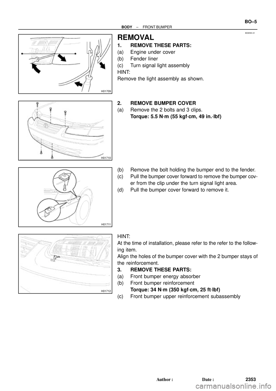
REMOVAL
1. REMOVE THESE PARTS:
(a) Engine under cover
(b) Fender liner
(c) Turn signal light assembly
HINT:
Remove the light assembly as shown.
2. REMOVE BUMPER COVER
(a) Remove the 2 bolts and 3 clips.
Torque: 5.5 N´m (55 kgf´cm, 49 in.´lbf)
(b) Remove the bolt holding the bumper end to the fender.
(c) Pull the bumper cover forward to remove the bumper cov-
er from the clip under the turn signal light area.
(d) Pull the bumper cover forward to remove it.
HINT:
At the time of installation, please refer to the refer to the follow-
ing item.
Align the holes of the bumper cover with the 2 bumper stays of
the reinforcement.
3. REMOVE THESE PARTS:
(a) Front bumper energy absorber
(b) Front bumper reinforcement
Torque: 34 N´m (350 kgf´cm, 25 ft´lbf)
(c) Front bumper upper reinforcement subassembly
Page 851 of 4592
BO0KY±01
H01713
Left Side Luggage Trim
Right Side Luggage Trim
Rear Bumper
Side Retainer Rear Bumper Energy Absorber Rear Bumper Reinforcement
Quarter Air Duct
Rear Bumper
Side Retainer
Rear Bumper Cover
5.0 (50, 43 in.´lbf)
5.0 (50, 43 in.´lbf)
N´m (kgf´cm, ft´lbf) : Specified Torque
34 (350, 25)
± BODYREAR BUMPER
BO±7
2355 Author�: Date�:
REAR BUMPER
COMPONENTS
Page 852 of 4592
BO0KZ±01
H01714
H01715
BO±8
± BODYREAR BUMPER
2356 Author�: Date�:
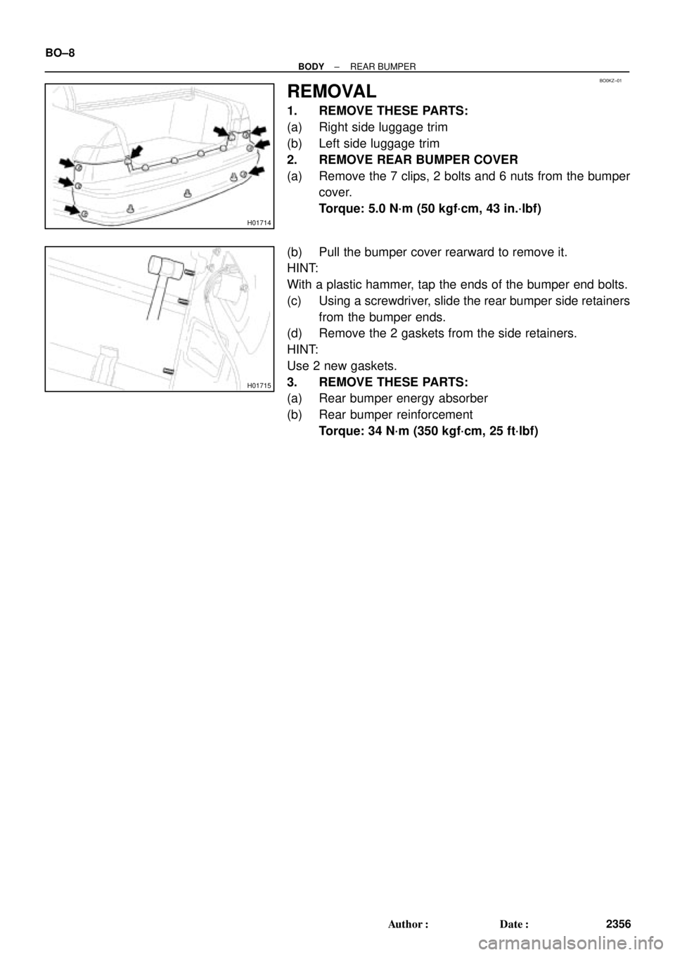
REMOVAL
1. REMOVE THESE PARTS:
(a) Right side luggage trim
(b) Left side luggage trim
2. REMOVE REAR BUMPER COVER
(a) Remove the 7 clips, 2 bolts and 6 nuts from the bumper
cover.
Torque: 5.0 N´m (50 kgf´cm, 43 in.´lbf)
(b) Pull the bumper cover rearward to remove it.
HINT:
With a plastic hammer, tap the ends of the bumper end bolts.
(c) Using a screwdriver, slide the rear bumper side retainers
from the bumper ends.
(d) Remove the 2 gaskets from the side retainers.
HINT:
Use 2 new gaskets.
3. REMOVE THESE PARTS:
(a) Rear bumper energy absorber
(b) Rear bumper reinforcement
Torque: 34 N´m (350 kgf´cm, 25 ft´lbf)
Page 854 of 4592
BO5235
Centering Bolt Bolt with Washer
BO0L1±01
N20963
N20964
N20965
BO±10
± BODYHOOD
2358 Author�: Date�:
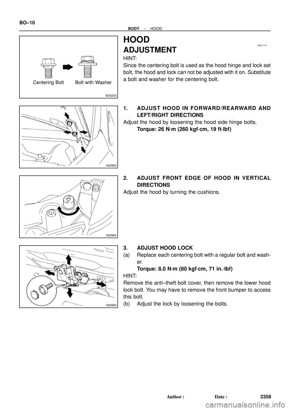
HOOD
ADJUSTMENT
HINT:
Since the centering bolt is used as the hood hinge and lock set
bolt, the hood and lock can not be adjusted with it on. Substitute
a bolt and washer for the centering bolt.
1. ADJUST HOOD IN FORWARD/REARWARD AND
LEFT/RIGHT DIRECTIONS
Adjust the hood by loosening the hood side hinge bolts.
Torque: 26 N´m (260 kgf´cm, 19 ft´lbf)
2. ADJUST FRONT EDGE OF HOOD IN VERTICAL
DIRECTIONS
Adjust the hood by turning the cushions.
3. ADJUST HOOD LOCK
(a) Replace each centering bolt with a regular bolt and wash-
er.
Torque: 8.0 N´m (80 kgf´cm, 71 in.´lbf)
HINT:
Remove the anti±theft bolt cover, then remove the lower hood
lock bolt. You may have to remove the front bumper to access
this bolt.
(b) Adjust the lock by loosening the bolts.
Page 855 of 4592
BO0L2±01
H01975
Door Lock
Cylinder
Outside Handle Front Door Belt Moulding
Door Glass
Door FrameFront Door Upper Moulding
Outside
Rear View
Mirror
Door Glass
Run
5.5 (55, 49 in.´lbf)
5.5 (55, 49 in.´lbf)
5.0 (50, 43 in.´lbf)�
Door Lock
23 (230, 17)
Window Regulator
8.0 (80, 69 in.´lbf)
Door Hinge
X6
7.5 (75, 66 in.´lbf)
Regulator
Motor
X3
31 (310, 22)
26 (260, 19)
8.0 (80, 71 in.´lbf)
30 (300, 22)
31 (310, 22)
Door
Check
Door Hinge
26 (260, 19)
Speaker
Power Window Switch Rear Lower
FrameFront Lower
FrameFront Window Upper
Garnish
Inside Handle Bezel
3.5 (35, 31 in.´lbf)
Driver's Side:
Regulator
Motor
Ptdt
N´m (kgf´cm, ft´lbf) : Specified torqueInside Handle
Door Trim
� Precoated part Door Lock StrikerService Hole Cover
± BODYFRONT DOOR
BO±11
2359 Author�: Date�:
FRONT DOOR
COMPONENTS
 Install the park/neutral position switch to the manual valve
shaft.
(b) Place the new locking pl")


5.5 (55, 49 in")