1999 TOYOTA CAMRY heater
[x] Cancel search: heaterPage 4205 of 4592
1
234
7
W± B
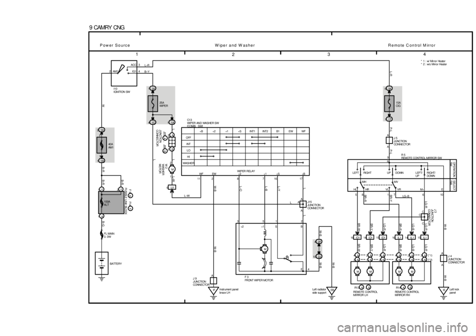
9 CAMRY CNG
W± B
2ACC
IG1 AM13
4
+1 +2 +B 1K 1
1K 2
A I10
IGNITION SW
40A
AM1
A
L±W
25A
WIPER
1B 11C 4
11A 1
1F 2F
1AEB EA11T
1 2
M
6IJ1WIPER RELAYA
B15A
CIG
17
M16
L±O
7 861K
2L±B
Instr ument panel
br ac e LH IF10 HI
6
A
L±Y
2L
11
L
IELeft kick
panel WASHER
M 1
L
ME
,
EBMC
L
M 42F16 I D1 14 I D15
1015 ID1
2J16 IL1 14 IL1 8
IL1 15 A
1
L
5 3
P±L
A 2
P± L
CC
L±R
A
W
RIGHT/
DOWN
(
*2) L
(
*1) L±R
A B±Y
9
100A
ALT
4 LO
W±B
INT
W± B
OFF
W±B
WF
B±G
EW
B± R
B1
B±R
INT2
B± R
INT1
BR±W
+S
BR±Y LG±R BR± RLG±B LG±RW± B
LG±R LG±R
LG±B
BR± R
LG±R
BR±Y
BR±W BR± R BR±Y
LG±B
FUSI BLE LI NK BLOCK W 2
WASHER
MO TO R
F 3
FRONT WIPER MOTORM+
J 3
JUNCTI ON
CONNECTOR
JUNCTION
CONNECTOR
J 9
JUNCTION
CONNECTORJ15
JUNCTI ON
CONNE CT OR
BATTERYC1 3
WIPER AND WASHER SW
[COMB. SW]
FL MAIN
3. 0W
OPERATION
SW
J 5
JUNCTION
CONNE CT OR
R 5
REMOTE CONTROL MIRROR SW
SELECT
SW
DOWN
VL RI GHT
HLLEFT/
UP
VR UP
HRMV LEFT
MH
J 4
JUNCTION
CONNECTOR
R e mo te C on trol M irro r
L±W
B
REMOTE CONTROL
MI RROR LH +1
B
RE MOT E CONTROL
MI RR O R R H2B 1B B 3 2B 1B 3B 4A 2A 3A 4A 2A 3A* 1 : w/ Mir ror Heater
* 2 : w/o Mirror Heater
WF EW +2 +1 +S +B
+2 B
E
,
Left radiator
side support S
W iper and W asher Power Source
B J25 J26A,
F F 9 F14A,
R1 3 A R1 4 A
W± B
Page 4225 of 4592
1
234
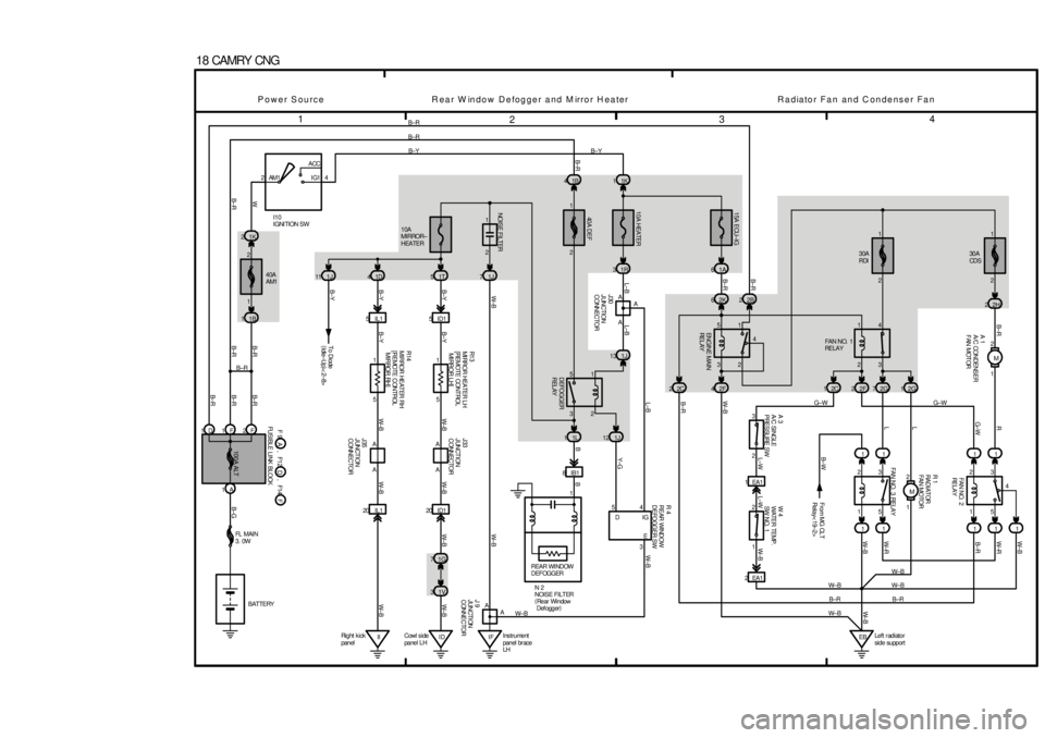
18 CAMRY CNG11F2F
1AB± R
B±R
40A
AM1B±R
1B 11K 22ACC
IG1 AM1 4B±Y
L±B
10A
MIRROR±
HEATER
10A HEATER15A ECU±IG
40A DEF
30A
RDI
A30A
CDS
1T 5 1D 41J71R 31A6
2H 2
5IL1 ID15
8IB11L 11J12
1V 3
II Ri g ht k i ck
panelID Cowl side
panel LHInstrument
panel br ace
LH IF
B±R
L±B
20 ID1 20 IL11K 1 1B 4
2K 62B2
1 2
M 4
3 1
2
2 1
3 54 1
2 5
3
42F 2C 2 1J 13
1G 72 3
1 2
2EA1 1EA1
ENGI NE MAI N
RE L AY
1 2
5 3
4 1 1
1 G±W
11 2G 7 2F 2 2C 112G
3
5 2
11 2
M
W± B 11
B±R 11
EBLeft r adiator
side support W± B
B±R
W± B
W± BB±W
G±W
L±W L±W W±BW±R
B±RW± B W± B
B±R R
G± W
L
L
B±R
B
A
Y±G
W±B
11
A22
FAN NO. 2
RE LA Y
R 1
RA DI AT OR
FAN MOTOR
A 3
A/C SI NGLE
PRESSURE SWFA N NO. 3 RE LA Y
J30
JUNCTION
CONNECTORW 4
WATER TEMP.
SW NO. 1 From MG CLT
Relay< 19±2>
FAN NO. 1
RE LA Y
DEFOGGER
RELAY
AA AA
W±B J33
JUNCTION
CONNECTOR
J35
JUNCTION
CONNECTOR B±Y
B±YB±Y
B±YW±B
W±B W±BW± B
B±G 100A ALT
B± R B± R
B±R B±R
I10
IGNI TION SW
BATTERY FL MAIN
3. 0WFUSIBLE LI NK BLOCK
B± Y
B± R
Power Source Rear W indow Defogger and M irror Heater Radiator Fan and Condenser Fan
D
B±R B±R
2 1
W± B
1J 11To Diode
(
Idle±Up)
<2±8> B±Y
1 2W
AA
J 9
JUNCTI ON
CONNECTOR
W± B
A 1
A/C CONDENSER
FAN MOTOR
W± B3 54
L±B W±B
DIG
E
R 4
REAR WINDOW
DEFOGGER SW
B±R1
NOI SE F I LT ER
REAR WI NDOW
DEFOGGER
N 2
NOI SE F I LT ER
(
Rear Window
Def ogger)1
D F 9 F12A, FF14 , W± B
W± B B
R1 3
MI RROR HEATER LH
[ RE MOTE CONT ROL
MI RR O R L H]
R14
MI RROR HEAT ER RH
[REMOTE CONTROL
MIRROR RH]
11
5 5
W±R
W± B
2
Page 4227 of 4592
1
234
1
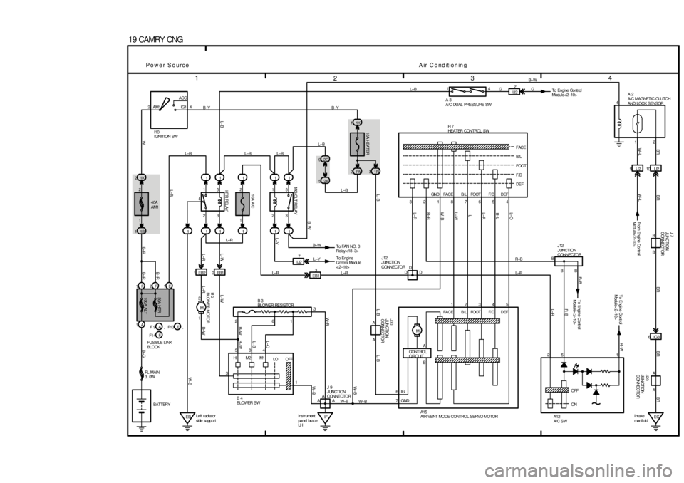
19 CAMRY CNG
1
1F 2F 1E1
100A ALT 50A HTR1B 12K
5
3 1K
1
2 4
B±Y AM1 IG1ACC
2
I10
IGNITION SW
2
1
EBLeft r adiator
side support51
2 1
3 5
41
8 1
10A A/C
11
1 15
1 EB2
HT R REL A Y
2EB1
1 2
M1
L±R2C 9
MG CLT RELAY 10A HEATER
1W 231R1K 1
1L±B
6
HI M2 M1
LO OFF 2
3
IF Ins tr ument
panel br ac e
LH1345 3
FACE 21
B/L 87
FOOT65
F/D4 GN D FA C E B / L FOOT F/ D D EFF/D
DEF FOOT B/L
FACE
DEF 2
M
EC Intake
man i f ol d6IG3
OFF
ON10 I J2 9IJ2
D J12
JUNCTION
CONNECTOR
EB13
BR
D
To Engine Cont rol
Module< 2±10>BR± B
D
GND
To Engine Cont rol
Module< 2±10>R± W
A
IGAJ20
JUNCTI ON
CONNECTOR
7
B±G
6
B±R B±R
B± R
A
WW±B
A
B±W L±R
A
L±R L±W L±WW± B
B±WL±B W± BW± B L±B L±B
L±O L±R R±B W± B
1
L±WL
A
L±RB± L
A
L±O
L±B
3
B±W
4L±B
BR
L±B
BR BR
W± L
L±B
1A40A
AM1
BATTERYL±B
2
L±Y
L±R L±RL±B14
GB±W
L±R R±B
215
L±R R± B
12
BR
A12
A/C SW A15
AIR VENT MODE CONTROL SERVO MOTOR B 4
BLOWER SW
L±B
L±B
4
FL MAIN
3. 0W
W± BCONT ROL
CIRCUIT
Power SourceAir ConditioningF 9 F1 3, AE
F1 4,
FUSI BL E L I NK
BL OCKFB B H 7
HEATER CONTROL SW
B 3
BLOWER RESISTORJ12
JUNCTION
CONNECTOR
J30
JUNCTION
CONNECTOR
A 2
A/C MAGNETIC CLUTCH
AND LOCK SENSOR A 3
A/C DUAL PRESSURE SW
B 2
BLOWER MOTOR
W±B 2
1B±Y
B±W
J 9
JUNCTION
CONNECTOR
L±Y
To FAN NO. 3
Relay< 18±3> B± WIJ22
To Engine Contr ol
Module< 2±10> G
J 7
JUNCTION
CONNE CT OR
Fr om Engine Contr ol
Module< 2±10> W±L
B B
IJ27
To Engine
Cont rol Module
< 2±10>
A
B
Page 4235 of 4592

B HOW TO USE THIS MANUAL
The ground points circuit diagram shows the connections from all major parts to the respective ground points. When
troubleshooting a faulty ground point, checking the system circuits which use a common ground may help you identify
the problem ground quickly. The relationship between ground points (
EA, IB and IC shown below) can also be
checked this way.
���� ���� ���� ���� ���� ���� ���� ���� ���� ���� ���� ���� ���� ���� ���� ���� ���� ���� ����
I GROUND POINT
FAN MAIN RELAY
FAN MAIN RELAY
A/C FAN RELAY NO.2
A/C FAN RELAY NO.3
RADIATOR FAN MOTOR
RETRACT CONTROL
RELAY
RETRACT MOTOR RH
RETRACT MOTOR LH
FRONT TURN SIGNAL
LIGHT RH
PARKING LIGHT RH
FRONT TURN SIGNAL
LIGHT LH
PARKING LIGHT LH
DOOR LOCK CONTROL
SW RH
DOOR KEY LOCK
SW RH
DOOR LOCK MOTOR
RH
BLOWER RESISTOR
A/C AMPLIFIER
RADIO AND PLAYER
HEATER RELAY
AUTO ANTENNA
MOTOR
BLOWER SW
PARKING BRAKE SW
COMBINATION METER
HORN SW [COMB. SW]
TURN SIGNAL FLASHER
DOOR KEY LOCK SW LH
DOOR LOCK MOTOR LH
FUEL CONTROL SW
WOOFER AMPLIFIER
COMBINATION METER
COMBINATION METER
FUEL SENDER
CIGARETTE LIGHTER
O/D MAIN SW
CLOCK
5
5
5
5
4
4
4
4
4BA15
IB18
EA2 10
3E5
3E
6 3G
13 3F
3 3D
1 3B
7
ID115
IC33
IA12
E 3
A
A AW±B
W±BW±B W±B
W±B W±B
W±B
W±B
W±B
W±B
W±B
W±B
W±B
W±B
W±B W±BW±B W±B W±B W±B
W±B W±B
W±BW±B
W±B
W±B
W±B W±B
W±B
BR
W±B
BR BRW±BW±B
W±B
W±B
W±B
W±B
W±B
W±B
W±B
W±B
W±B W±B
W±B
W±B
W±B
W±B
BR W±B
BR BR
BR W±B W±BW±B
W±BW±BBR W±B (4A±GZE)
W±B A A A
I 6
I 6
I 2
I 2
I 2
B 5I 5
I 5
I 5
B 5
B 5
B 5
I 5
I 5
I 3I 3
E 3
E 3
E 3
E 2
E 4
E 5
E 4
E 5
E 6E 4
E 4
B 4
EAI 4
B 4
B 4
I 4I 8
IBIC
3C7
4
JUNCTION
CONNECTOR J 1
4
DOOR LOCK CONTROL
RELAY
ELECTRICAL IDLE-UP
CUT RELAY (M/T)FRONT SIDE MARKER
LIGHT RH
FRONT SIDE MARKER
LIGHT LH
BRAKE FLUID LEVEL
WARNING SW
UNLOCK WARNING
SW WIPER AND WASHER
SW [COMB. SW] LIGHT CONTROL SW
[COMB. SW] HEATER CONTROL
ASSEMBLY
HEATER SERVO
MOTOR AMPLIFIER
DIMMER SW
[COMB. SW]
CRUISE CONTROL
MIRROR SW
REAR WINDOW
DEFOGGER SW
POWER WINDOW
MASTER SW
POWER WINDOW
CONTROL RELAY
DOOR LOCK CONTROL
SW
REMOTE CONTROL
MIRROR SW
* The system shown here is an EXAMPLE ONLY. It is different to the actual circuit shown in the SYSTEM CIRCUITS SECTION.
Page 4257 of 4592

G ELECTRICAL WIRING ROUTING
Position of Parts in Instrument Panel
A 12 A/C Amplifier
A 13 A/C Evaporator Temp. Sensor
A 14 A/C SW
A 15 ABS and Traction ECU
A 16 ABS and Traction ECU
A 17 ABS and Traction ECU
A 18 ABS ECU
A 19 ABS ECU
A 20 Air Vent Mode Control Servo Motor
A 22 Airbag Squib (Front Passenger Airbag Assembly)
A 23 Airbag Squib (Steering Wheel Pad)
A 24 Ashtray Illumination
A 33 A/C Blower Motor Linear Controller
A 34 A/C Control Assembly
A 35 A/C Control Assembly
A 36 A/C Room Temp. Sensor
A 37 A/C Solar Sensor
A 38 Air Inlet Control Servo Motor
A 39 Air Mix Control Servo Motor
A 40 Automatic Light Control Sensor
B 3 Blower Motor
B 4 Blower Resistor
B 5 Blower SW
B 8 Blower Resistor (Low Speed)
C 4 Cigarette Lighter
C 5 Cigarette Lighter Illumination
C 6 Clock
C 7 Clutch Start SW
C 8 Combination Meter
C 9 Combination Meter
C 10 Combination MeterC 11 Combination SW
C 12 Combination SW
C 13 Combination SW
C 14 Cruise Control Clutch SW
C 15 Cruise Control ECU
C 17 Center Airbag Sensor Assembly
C 18 Center Airbag Sensor Assembly
C 19 Center Airbag Sensor Assembly
D 4 Data Link Connector 2
D 5 Data Link Connector 3
D 6 Daytime Running Light Relay (Main)
D 7 Diode (Courtesy)
D 10 Diode (Dome)
D 11 Diode (Idle±Up)
E 7 Engine Control Module
E 8 Engine Control Module
E 9 Engine Control Module
E 10 Engine Control Module
E 11 Engine Control Module
G 3 Glove Box Light and SW
H 7 Hazard SW
H 8 Heated Oxygen Sensor (Bank 1 Sensor 2)
H 9 Heater Control SW
I 15 Ignition Key Cylinder Light
I 16 Ignition SW
I 17 Integration Relay
I 18 Integration Relay
Page 4276 of 4592
1230A POWER
1240A DEF
12
40A AM1 1B4
1B1
1K2
1K6
1K1
1K3
1K4
1K5
1B5
2
221J7
2
2
2
22
2 AM1
AM2 7 23
6 ACC
IG1
IG2
ST24
8I 1
12
IG 12
13 25A DOOR
15A STOP
7. 5A OBDTAI LL IGHT REL AY10A TAIL
7. 5A PANEL
POWER RELAY
NOISE FILTER
NOISE FILTER
DEFOGGER RELAY
10A MIRROR±HEATER
15A CIG
7. 5A RAD±NO. 2
15A POWER±OUTLET
15A ECU±IG
10A HEATER
10A GAUGE
25A WIPER
7. 5A TURN
5A IGN
5A STARTER
5A DRL NO. 2
DIM
RELAY10A H±LP RH (
LWR)
10A H±LP LH (
LWR)
JUNCTION
CONNECTOR IGNITION SW I16
J11 B±R
B±R
W B±R
W± B
L±R
B±Y
B±R
R1
1 5
1
5
1
5
13
2
3
2
2
2
3
2
* 1 : TMC MADE
* 2 : TMMK MADE
* 3 : EXCEPT TAIWAN* 4 : W/ TRACTION CONTROL
* 5 : W/ O TRACTI ON CONTROL W±R
R
R±L W±R
(
*8)
(
*8)14
2
3W±R
R±B
R±L(
*8)
R±YR±G
R
A
W±B
1A6
B±R
R
* 6 : CALIFORNIA* 7 : TMC MADE EXCEPT 5S±FE W/O ABS
* 8 : W/ DAYTIME RUNNING LIGHT
* 9 : W/O DAYTIME RUNNING LIGHT
Page 4293 of 4592
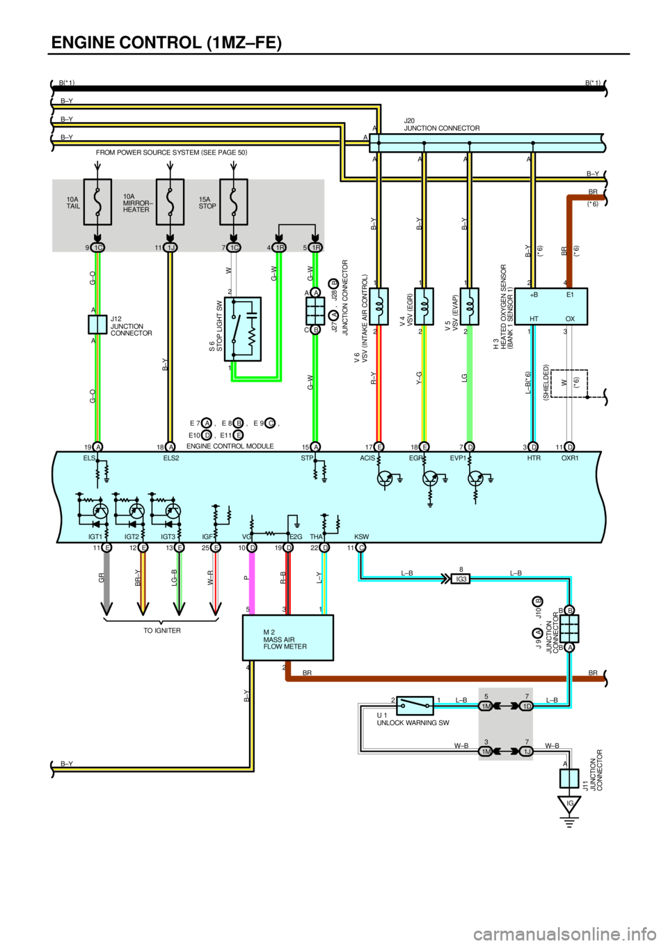
ENGINE CONTROL (1MZ±FE)
10A
MIRROR±
HEATER FROM POWER SOURCE S YSTEM (
SEE PAGE 50)
1J 1115A
STOP
1C 7 10A
TAI L
1C 9
2 1
2 1
2 1
D 19 D 10 E 25 E 13 E 12 E 111R 5
2 4AAA
53A
A
B±Y B±Y B±Y B±Y
B±Y
E2 G VG IGF IGT3 IGT2 IGT1EVP1 EGR ACIS STP ELS2 ELS
LG Y±G R±Y G± W G± WG± WW B±YG± O G±O
B±Y B±Y B±Y R±BP W±R LG±B BR±YGR
B±Y
VSV (
INTAKE AIR CONTROL)
VSV (
EGR)
VSV (
EVAP) V 6
V 5 STOP LIGHT SW S 6
JUNCTION CONNECTOR
J20
MASS AIR
FL OW METE R M 2 1 2
BR C 11KSW
IGB B
A B
J 9
JUNCTION
CONNECTORA
A
JUNCTION
CONNECTOR J11
UNLOCK WARNING SW U 1L±B L±B
W±B W±B BR B(
*1)
B(
*1)
D 22
1 THA
L±Y
J12
JUNCTION
CONNECTORB CA A
JUNCTION CONNECTORB J2 7 J28
A
A
A
D 7 E 18 E 17 A 18 19A 15 A
B , J10
IG38
1D7
1M5
1 2
1J7
1M3
,
1R 4
E 7 BA, E 8
E10
ENGINE CONTROL MODULEE D, E11C , E 9 ,
V 4
D 3D11BR A
13 24
HT OX
W L±B(
*6)
BR B±Y
(
SHIELDED)(
*6)
(
*6)
(
*6)
(
*6)
HTR OXR1+B E1
HEATED OXYGEN SENSOR
(
BANK 1 SENSOR 1) H 3
L±B L±B
TO IGNI TER
Page 4298 of 4592

This system utilizes an engine control module and maintains overall control of the engine, transmission and so on. An outline
of the engine control is explained here.
1. INPUT SIGNALS
(1) Engine coolant temp. signal circuit
The engine coolant temp. sensor detects the engine coolant temp. and has a built±in thermistor with a resistance which
varies according to the water temp. is input into TERMINAL THW of the engine control module as a control signal.
(2) Intake air temp. signal circuit
The intake air temp. sensor is installed in the mass air flow meter and detects the intake air temp., which is input as a
control signal into TERMINAL THA of the engine control module.
(3) Oxygen sensor signal circuit
The oxygen density in the exhaust gases is detected and input as a control signal into TERMINALS OXL1, OXR1
(Except California) and OXS of the engine control module. To maintain stable detection performance by the heated
oxygen sensor, a heater is used for warming the sensor. The heater is also controlled by the engine control module
(HTL, HTR (Except California) and HTS).
(4) RPM signal circuit
Camshaft position and crankshaft position are detected by the camshaft position sensor and crankshaft position sensor.
The camshaft position is input as a control signal to TERMINAL G22+ of the engine control module, and the engine
RPM is input into TERMINAL NE+.
(5) Throttle signal circuit
The throttle position sensor detects the throttle valve opening angle as a control signal, which is input into TERMINAL
VTA1 of the engine control module.
(6) Vehicle speed signal circuit
The vehicle speed sensor, installed inside the transmission, detects the vehicle speed and inputs a control signal into
TERMINAL SPD of the engine control module.
(7) Park/Neutral position SW signal circuit
The Park/Neutral position SW detects whether the shift position is in neutral, parking or not, and inputs a control signal
into TERMINAL STA of the engine control module.
(8) A/C SW signal circuit
The A/C control assembly (Automatic A/C) or A/C Amplifier (Manual A/C) inputs the A/C operations into TERMINAL A/C
of the engine control module as a control signal.
(9) Battery signal circuit
(California or w/ engine immobiliser and/or traction control)
Voltage is always supplies to TERMINAL BATT of the engine control module.
If you turn on the ignition SW, the current goes from TERMINAL MREL of the engine control module to the EFI relay and
put on the relay, and the voltage related to the engine control module operation is supplied to TERMINAL +B of the
engine control module through the EFI relay.
(Except California or w/ engine immobiliser and/or traction control)
Voltage is constantly applied to TERMINAL BATT of the engine control module. When the ignition SW is turned on,
voltage for engine control module start±up power supply is applied to TERMINAL +B of engine control module via EFI
relay.
(10) Intake air volume signal circuit
Intake air volume is detected by the mass air flow meter and a signal is input into TERMINAL VG of the engine control
module as a control signal.
(11) NSW signal circuit
To confirm whether the engine is cranking, the voltage applied to the starter motor during cranking is detected and the
signal is input into TERMINAL NSW of the engine control module as a control signal.
(12) Engine knock signal circuit
Engine knocking is detected by the knock sensor 1 and 2, then the signals are input into TERMINALS KNKR and KNKL
of the engine control module as a control signal.
(13) Air fuel ratio signal circuit (California)
The air fuel ratio is detected and input as a control signal into TERMINALS AFL+, AFR+ of the engine control module.
SYSTEM OUTLINE