Page 3822 of 4592

Toyota Supports ASE CertificationPage 1 of 2
EL002±98Title:
CIGARETTE LIGHTER SERVICE
Models:
All Models
Technical Service
BULLETIN
Apirl 10, 1998
When receiving customer complaints to repair the lighter or lighter socket, please
carefully investigate the cause of the failure to prevent further occurrences. If the
customer uses the wrong size lighter element or power accessory plug, damage may
occur to the lighter socket. When applicable, instruct the customer to replace the lighter
element with original equipment components or to use an appropriate sized accessory
plug. Dimensional information included within this document will instruct you on
component specifications.
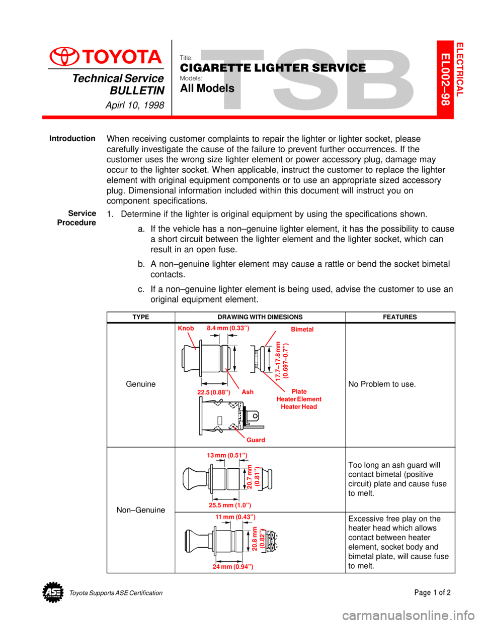
1. Determine if the lighter is original equipment by using the specifications shown.
a. If the vehicle has a non±genuine lighter element, it has the possibility to cause
a short circuit between the lighter element and the lighter socket, which can
result in an open fuse.
b. A non±genuine lighter element may cause a rattle or bend the socket bimetal
contacts.
c. If a non±genuine lighter element is being used, advise the customer to use an
original equipment element.
TYPEDRAWING WITH DIMESIONSFEATURES
Genuine
Knob
Bimetal
Plate
Heater Element
Heater Head
Guard Ash 8.4 mm (0.33º)
17.7±17.8 mm
(0.697±0.7º)
22.5 (0.88º)No Problem to use.
Non±Genuine
13 mm (0.51º)
20.7 mm
(0.81º)
25.5 mm (1.0º)
Too long an ash guard will
contact bimetal (positive
circuit) plate and cause fuse
to melt.
Non±Genuine11 mm (0.43º)
20.8 mm
(0.82º)
24 mm (0.94º)
Excessive free play on the
heater head which allows
contact between heater
element, socket body and
bimetal plate, will cause fuse
to melt.
ELECTRICAL
Introduction
Service
Procedure
Page 3827 of 4592
Toyota Supports ASE CertificationPage 1 of 4
EL007±00Title:
HEATER CONTROL ASSEMBLY
INSTRUCTIONS
Models:
'97 ± '99 Camry
Technical Service
BULLETIN
April 14, 2000
The attached instructions have been developed to supplement the Repair Manual to
assure corrrect cable routing of the heater control assembly during a service repair.
PUBLICATIONNUMBER
1997 Camry Repair Manual, Vol. 2RM503U2
1998 Camry Repair Manual, Vol. 2RM589U2
1999 Camry Repair Manual, Vol. 2RM654U2
NOTE:
For maximum heater performance the coolant ratio should be 50 to 60 percent.
�1997 ± 1999 model year Camry
OP CODEDESCRIPTIONTIMEOPNT1T2
N/ANot Applicable to Warranty ±±±±
ELECTRICAL
Introduction
Applicable
Vehicles
Warranty
Information
Page 3828 of 4592
POOR HEATER PERFORMANCE ± EL007±00 April 14, 2000
Page 2 of 4
A. Pull out the inner cable of the
REC/FRE cable until the link of the
A/C unit contacts the link stopper.
View A
To p
Left Side
RearView A
Link
Should make
contact here.
Link Stopper
B. Set the air intake selector of the
heater control unit all the way to the
ªFRESHº position.
C. Attach the REC/FRE cable to the
heater control unit lever pin and clamp
the outer cable to the secure clamp.
NOTE:
Clamp the cable while pushing the
outer cable to the A/C unit assembly
side. Installation
ProcedureLever
Page 3829 of 4592
POOR HEATER PERFORMANCE ± EL007±00 April 14, 2000
Page 3 of 4
D. Install the heater control panel to the
instrument panel with 4 screws.
NOTE:
Make sure air mix cable is routed
outside of the brace.
REC/FRE Cable
(from A/C Unit)
Step (C)Instrument Panel
Step (A)
Step (D)
Air Mix Cable
Screw (4)
Right Side Front SideTo p
Installation
Procedure
(Continued)
Page 3830 of 4592

POOR HEATER PERFORMANCE ± EL007±00 April 14, 2000
Page 4 of 4
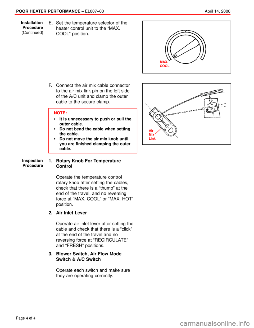
E. Set the temperature selector of the
heater control unit to the ªMAX.
COOLº position.
F. Connect the air mix cable connector
to the air mix link pin on the left side
of the A/C unit and clamp the outer
cable to the secure clamp.
NOTE:
�It is unnecessary to push or pull the
outer cable.
�Do not bend the cable when setting
the cable.
�Do not move the air mix knob until
you are finished clamping the outer
cable.
1. Rotary Knob For Temperature
Control
Operate the temperature control
rotary knob after setting the cables,
check that there is a ªthumpº at the
end of the travel, and no reversing
force at ªMAX. COOLº or ªMAX. HOTº
position.
2. Air Inlet Lever
Operate air inlet lever after setting the
cable and check that there is a ªclickº
at the end of the travel and no
reversing force at ªRECIRCULATEº
and ªFRESHº positions.
3. Blower Switch, Air Flow Mode
Switch & A/C Switch
Operate each switch and make sure
they are operating correctly.
Installation
Procedure
(Continued)
MAX.
COOL
Air
Mix
Link
Inspection
Procedure
Page 4017 of 4592

B HOW TO USE THIS MANUAL
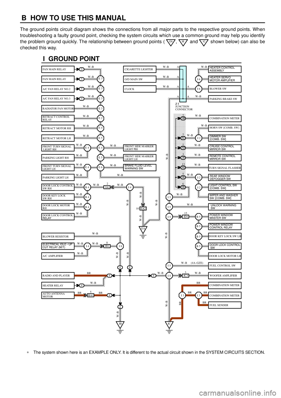
The ground points circuit diagram shows the connections from all major parts to the respective ground points. When
troubleshooting a faulty ground point, checking the system circuits which use a common ground may help you identify
the problem ground quickly. The relationship between ground points (
EA, IB and IC shown below) can also be
checked this way.
���� ���� ���� ���� ���� ���� ���� ���� ���� ���� ���� ���� ���� ���� ���� ���� ���� ���� ����
I GROUND POINT
FAN MAIN RELAY
FAN MAIN RELAY
A/C FAN RELAY NO.2
A/C FAN RELAY NO.3
RADIATOR FAN MOTOR
RETRACT CONTROL
RELAY
RETRACT MOTOR RH
RETRACT MOTOR LH
FRONT TURN SIGNAL
LIGHT RH
PARKING LIGHT RH
FRONT TURN SIGNAL
LIGHT LH
PARKING LIGHT LH
DOOR LOCK CONTROL
SW RH
DOOR KEY LOCK
SW RH
DOOR LOCK MOTOR
RH
BLOWER RESISTOR
A/C AMPLIFIER
RADIO AND PLAYER
HEATER RELAY
AUTO ANTENNA
MOTOR
BLOWER SW
PARKING BRAKE SW
COMBINATION METER
HORN SW [COMB. SW]
TURN SIGNAL FLASHER
DOOR KEY LOCK SW LH
DOOR LOCK MOTOR LH
FUEL CONTROL SW
WOOFER AMPLIFIER
COMBINATION METER
COMBINATION METER
FUEL SENDER
CIGARETTE LIGHTER
O/D MAIN SW
CLOCK
5
5
5
5
4
4
4
4
4BA15
IB18
EA2 10
3E5
3E
6 3G
13 3F
3 3D
1 3B
7
ID115
IC33
IA12
E 3
A
A AW±B
W±BW±B W±B
W±B W±B
W±B
W±B
W±B
W±B
W±B
W±B
W±B
W±B
W±B W±BW±B W±B W±B W±B
W±B W±B
W±BW±B
W±B
W±B
W±B W±B
W±B
BR
W±B
BR BRW±BW±B
W±B
W±B
W±B
W±B
W±B
W±B
W±B
W±B
W±B W±B
W±B
W±B
W±B
W±B
BR W±B
BR BR
BR W±B W±BW±B
W±BW±BBR W±B (4A±GZE)
W±B A A A
I 6
I 6
I 2
I 2
I 2
B 5I 5
I 5
I 5
B 5
B 5
B 5
I 5
I 5
I 3I 3
E 3
E 3
E 3
E 2
E 4
E 5
E 4
E 5
E 6E 4
E 4
B 4
EAI 4
B 4
B 4
I 4I 8
IBIC
3C7
4
JUNCTION
CONNECTOR J 1
4
DOOR LOCK CONTROL
RELAY
ELECTRICAL IDLE-UP
CUT RELAY (M/T)FRONT SIDE MARKER
LIGHT RH
FRONT SIDE MARKER
LIGHT LH
BRAKE FLUID LEVEL
WARNING SW
UNLOCK WARNING
SW WIPER AND WASHER
SW [COMB. SW] LIGHT CONTROL SW
[COMB. SW] HEATER CONTROL
ASSEMBLY
HEATER SERVO
MOTOR AMPLIFIER
DIMMER SW
[COMB. SW]
CRUISE CONTROL
MIRROR SW
REAR WINDOW
DEFOGGER SW
POWER WINDOW
MASTER SW
POWER WINDOW
CONTROL RELAY
DOOR LOCK CONTROL
SW
REMOTE CONTROL
MIRROR SW
*The system shown here is an EXAMPLE ONLY. It is different to the actual circuit shown in the SYSTEM CIRCUITS SECTION.
Page 4039 of 4592

G ELECTRICAL WIRING ROUTING
Position of Parts in Instrument Panel
A 11 A/C Evaporator Temp. Sensor
A 12 A/C SW
A 13 ABS ECU
A 14 ABS ECU
A 15 Air Vent Mode Control Servo Motor
A 16 Airbag Squib (Front Passenger Airbag Assembly)
A 17 Airbag Squib (Steering Wheel Pad)
A 18 Ashtray Illumination
B 2 Blower Motor
B 3 Blower Resistor
B 4 Blower SW
C 4 Center Airbag Sensor Assembly
C 5 Center Airbag Sensor Assembly
C 6 Center Airbag Sensor Assembly
C 7 Cigarette Lighter
C 8 Cigarette Lighter Illumination
C 9 Clock
C 10 Combination Meter
C 11 Combination Meter
C 12 Combination Meter
C 13 Combination SW
C 14 Combination SW
C 15 Combination SW
C 16 Cruise Control ECUD 2 Data Link Connector 2
D 3 Data Link Connector 3
D 4 Diode (Courtesy)
D 5 Diode (Dome)
D 6 Diode (Idle±Up)
E 4 Engine Control Module
E 5 Engine Control Module
E 6 Engine Control Module
E 7 Engine Control Module
G 3 Glove Box Light and SW
H 5 Hazard SW
H 6 Heated Oxygen Sensor
H 7 Heater Control SW
I 9 Ignition Key Cylinder Light
I 10 Ignition SW
I 11 Integration Relay
I 12 Integration Relay
Page 4052 of 4592
1230A POWER
1240A DEF
12
40A AM1 1B4
1B1
1K2
1K6
1K1
1K3
1K4
1K5
1B51J7
AM1
AM2 7 23
6 ACC
IG1
IG2
ST24
8I 2
IF 25A DOOR
15A STOP
7. 5A OBDTAI LL IGHT REL AY10A TAIL
7. 5A PANEL
POWER RELAY
NOISE FILTER
NOISE FILTER
DEFOGGER RELAY
10A MIRROR±HEATER
15A CIG
7. 5A RAD±NO. 2
15A POWER±OUTLET
15A ECU±IG
10A HEATER
10A GAUGE
25A WIPER
7. 5A TURN
5A IGN
5A STARTER
JUNCTION
CONNECTOR IGNITION SW I10
J 9 B±R
B±R
W B±R
W±B
L±R
B±Y
B±R
R1
1 5
1
5
1
5
13
2
3
2
2
2
3
2
W±R
W±R
A
W±B
1A6
B±R