Page 4299 of 4592

ENGINE CONTROL (1MZ±FE)
2. CONTROL SYSTEM
*SFI system
The SFI system monitors the engine condition through the signals, which are input from each sensor (Input signals (1) to
(12) ). The best fuel injection volume is decided based on this data and the program memorized by the engine control
module, and the control signal is output to TERMINALS #10, #20, #30, #40, #50 and #60 of the engine control module
to operate the injector (Inject the fuel). The SFI system produces control of fuel injection operation by the engine control
module in response to the driving conditions.
*ESA system
The ESA system monitors the engine condition through the signals, which are input to the engine control module from
each sensor (Input signals from 1, 3, 4, 12). The best ignition timing is decided according to this data and the memorized
data in the engine control module and the control signal is output to TERMINALS IGT1, IGT2 and IGT3. This signal
controls the igniter to provide the best ignition timing for the driving conditions.
*Heated oxygen sensor heater control system
The heated oxygen sensor heater control system turns the heater on when the intake air volume is low (Temp. of
exhaust emissions is low), and warms up the heated oxygen sensor to improve detection performance of the sensor.
The engine control module evaluates the signals from each sensor (Input signals from 1, 4, 9, 10), current is output to
TERMINALS HTL, HTR and HTS, controlling the heater.
*Idle air control system
The idle air control system (Rotary solenoid type) increases the RPM and provides idle stability for fast idle±up when the
engine is cold, and when the idle speed has dropped due to electrical load and so on, the engine control module
evaluates the signals from each sensor (Input signals from 1, 4, 5, 8, 9), current is output to TERMINALS RSO and RSC
to control idle air control valve.
*EGR control system
The EGR control system detects the signal from each sensor (Input signals from 1, 4, 9, 10), and outputs current to
TERMINAL EGR to control the VSV (EGR).
The EGR valve position sensor is mounted on the EGR valve. this sensor converts the EGR valve opening height into a
voltage and sends it to the engine control module as the EGR valve position signal.
*ACIS
ACIS includes a valve in the bulkhead separating the surge tank into two parts. This valve is opened and closed in
accordance with the driving conditions to control the intake manifold length in two stages for increased engine output in
all ranges from low to high speeds.
The engine control module judges the engine speed by the signals ( (4), (5) ) from each sensor and outputs signals to
the TERMINAL ACIS to control the VSV (Intake air control).
3. DIAGNOSIS SYSTEM
With the diagnosis system, when there is a malfunction in the engine control module signal system, the malfunctioning
system is recorded in the memory.
4. FAIL±SAFE SYSTEM
When a malfunction occurs in any systems, if there is a possibility of engine trouble being caused by continued control
based on the signals from that system, the fail±safe system either controls the system by using data (Standard values)
recorded in the engine control module memory or else stops the engine.
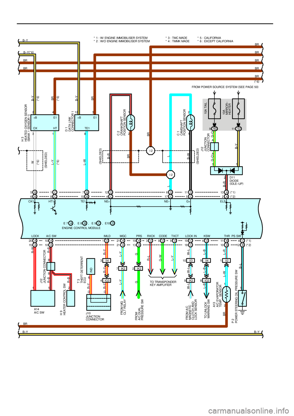
Page 4310 of 4592

FROM POWER SOURCE SYSTEM (
SEE PAGE 50)
1C 91J11
1 2
2 1
IK2 7IK22
IK2 9II3 10 II21
1 I 2 I 2
A 10 A 20 A21 A19 C19 B11 C4 B 6C8B15 C4C17 C5A2
2 1 B8 1 3
2 A
B4 2123
A
1 3
2 5 1
BR
B±YBR BRB±Y(
*6) B±Y
BR
BR
BR
BR
BR
B±Y PS SW THR LOCK IN PRS MGC TE1
A/C SW LOCK
B±LL±R L±W BRW±L W±L W±LG L±Y
G L±YR±BR±B R±W
R±BW
L±Y
L±W
B±R
BR
L
B±W
G±O G±O
B±YB±Y
BR
B±Y
BR
OX1 HT1 TE1 NE+ NE± G+ E LSE1 +B
10A TAIL
10A
MIRROR±
HEATER (
SHIELDED)
(
SHIELDED) (
SHIELDED)
(
*6) (
*6)(
*6)
(
*6)
L
B±R
(
*6)
DIODE
(
IDLE±UP)
HEATED OXYGEN SENSOR
(
BANK 1 SENSOR 1)
DATA LINK
CONNECTOR 1
CRANKSHAFT
POSITION SENSOR
CAMSHAFT
POSITION SENSOR
JUNCTION
CONNECTORH 3
D 1
C 2
C 1
J12
D11
JUNCTION CONNECTOR
A/C SWHEATER CONTROL SW
A/C EVAPORATOR
TEMP. SENSOR
POWER STEERING OIL PRESSURE SWFROM MG
CLT RELAY
FROM
A/C DUAL
PRESSURE SW
FROM A/ C
MAGNETIC
CLUTCH AND
LOCK SENSORJ12
A13
P 2H 9
A14* 5 : CALIFORNIA
* 6 : EXCEPT CALIFORNIA
BR
ENGINE CONTROL MODULEB E 7 E 8ACE 9 +B E1
OX HT* 1 : W/ ENGINE IMMOBILISER SYSTEM
* 2 : W/O ENGINE IMMOBILISER SYSTEM
, , DE10 , B 5C1B7D12 D6D11 A13(
*1)
(
*2)
IG3 8D 4KSW
L±B L±B L±B
TO UNLOCK
WARN ING SW
A 10 A 15 A21 A13 C18 B10 B12
IG3 4II4 3D 1IMLD
R±Y R±Y R±Y
6
IND R±YTHEFT DETERRENT
ECU T 3
(
*1)
(
*2) D 3D8D9TXCT CODE RXCK
R±L
G± W
L±Y
TO TRANSPONDER
KEY AMPLIFIER
DD
J10
JUNCTION
CONNECTORII4 9 * 3 : TMC MADE
* 4 : TMMK MADE
Page 4491 of 4592
REMOTE CONTROL MIRROR
1T 1
IE1 16 IE114 IE115 IM116 IM114 IM115
IF 58 17 6 10A
A 9 A
A
MM MM15A
CIG
OPERATION SW SELECT SW
JUNCTION
CONNECTOR
JUNCTION
CONNECTOR REMOTE CONTROL MIRROR SW
P±L P±L BR±Y BR ±Y
LG±R
LG±R LG±BBR±R
LG±R
W±B BR±R BR±W
BR ±Y
LG±R
BR±R
LG±B
LG±R
W± BBR±W
FROM POWER SOURCE SYSTEM (
SEE PAGE 50)
LEFT
RIGHT
UP
DOWN
L EFT/
UP
RIGHT/
DOWN
J 6
R 6
J 5
C 3B 4
C 1B 2
C 2B 3
C 3B 4
C 1B 2
C 2B 3 (
*2)
(
*3)(
*2)
(
*3)* 1 : TMMK MADE
* 2 : TMC MADE W/ MIRROR HEATER
B R16 , A
REMOTE CONTROL
MIRROR LHB R17 , A
REMOTE CONTROL
MIRROR RH B
HL HR V L VR M+ E
C CC
A 1A3A2A1A3A2 (
*1)(
*1) JUNCTION
CONNECTOR J 4* 3 : TMC MADE W/O MIRROR HEATER
LG±B
C , C , MH MV
Page 4492 of 4592

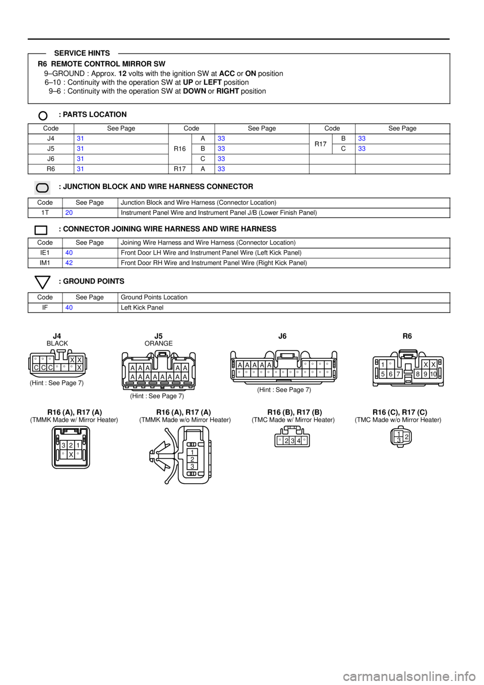
R6 REMOTE CONTROL MIRROR SW
9±GROUND : Approx. 12 volts with the ignition SW at ACC or ON position
6±10 : Continuity with the operation SW at UP or LEFT position
9±6 : Continuity with the operation SW at DOWN or RIGHT position
: PARTS LOCATION
CodeSee PageCodeSee PageCodeSee Page
J431A33R17B33
J531R16B33R17C33
J631C33
R631R17A33
: JUNCTION BLOCK AND WIRE HARNESS CONNECTOR
CodeSee PageJunction Block and Wire Harness (Connector Location)
1T20Instrument Panel Wire and Instrument Panel J/B (Lower Finish Panel)
: CONNECTOR JOINING WIRE HARNESS AND WIRE HARNESS
CodeSee PageJoining Wire Harness and Wire Harness (Connector Location)
IE140Front Door LH Wire and Instrument Panel Wire (Left Kick Panel)
IM142Front Door RH Wire and Instrument Panel Wire (Right Kick Panel)
: GROUND POINTS
CodeSee PageGround Points Location
IF40Left Kick Panel
AAA AA
AAAAAAAAX X � � �
CCC���XAAAAA����
�������������
10 9 8 7 6 5X X � 1
321
� X �1
2
3 BLACK
(Hint : See Page 7)
(Hint : See Page 7)(Hint : See Page 7) ORANGE
J6 R6
(TMMK Made w/ Mirror Heater) (TMMK Made w/o Mirror Heater) (TMC Made w/ Mirror Heater) (TMC Made w/o Mirror Heater)
J5 J4
R16 (A), R17 (A) R16 (A), R17 (A) R16 (B), R17 (B) R16 (C), R17 (C)
�234�1
32
SERVICE HINTS
Page 4493 of 4592

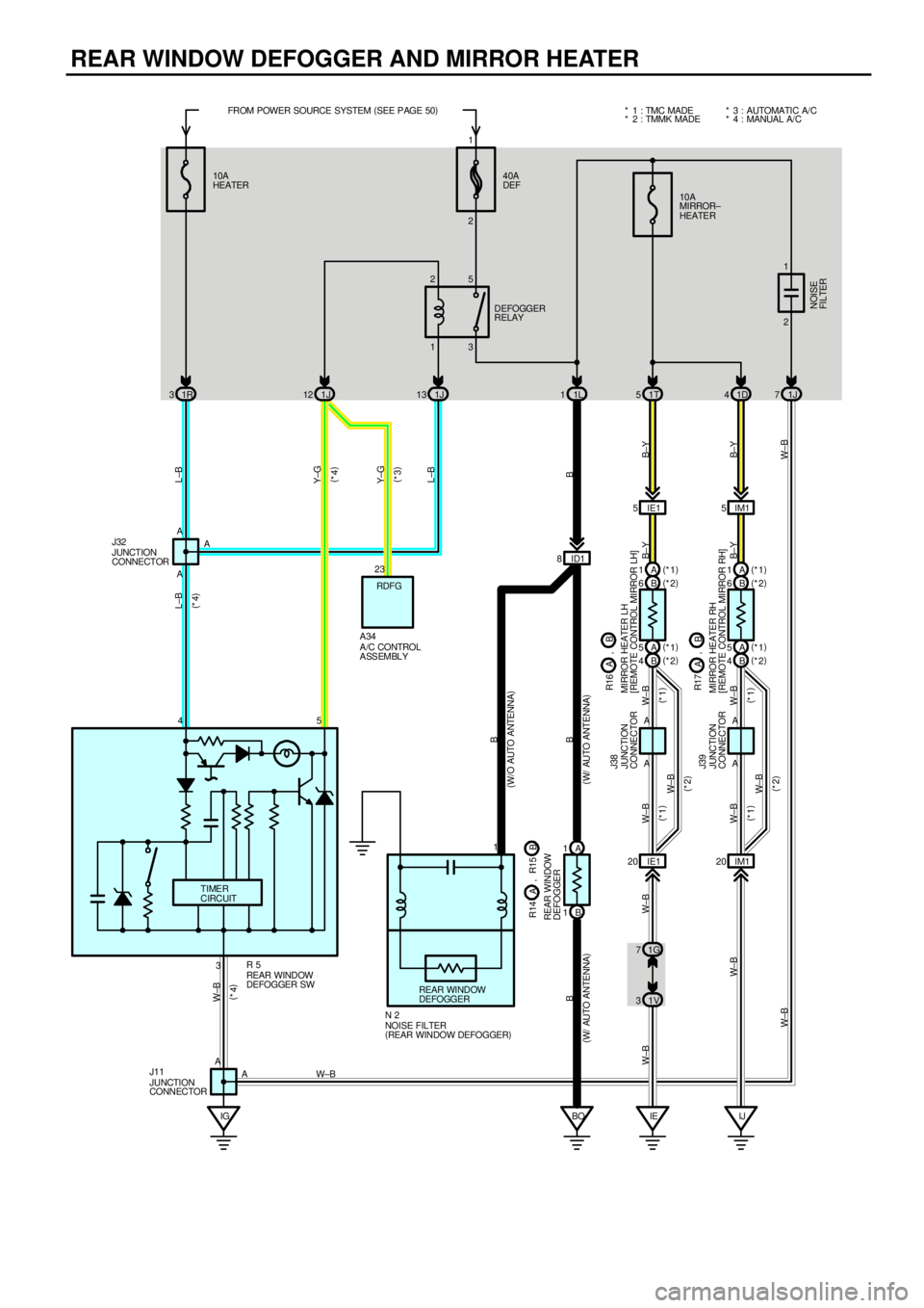
REAR WINDOW DEFOGGER AND MIRROR HEATER
1R 31J13
IE BOA 1
B 1
IJ 1V 31G 7A A 10A
HEATER40A
DEF
DEFOGGER
RELAY
JUNCTION
CONNECTOR
FROM POWER SOURCE SYSTEM (
SEE PAGE 50)
W±B W±BBB
W±BJ38
13 25
ID1 8
B
2
IGIE1 20 IM120 IE1 5IM15 10A
MIRROR±
HEATER
1T 51D4 1L 1 1J 12
3 A
A
A 45 A
A A
REAR WINDOW
DEFOGGER SW R 5 JUNCTION
CONNECTOR J32
JUNCTION
CONNECTOR J39
MIRROR HEATER RH
[REMOTE CONTROL MIRROR RH] MIRROR HEATER LH
[REMOTE CONTROL MIRROR LH]
JUNCTION
CONNECTOR J11
L±B
L±B Y±G L±B
B W±B
W± BW±B
W±B W±B
B±Y B±Y B±Y
B±Y
1
TIMER
CIRCUIT
(
W/ AUTO ANTENNA) (
W/ AUTO ANTENNA)
REAR WINDOW
DEFOGGER
(
W/O AUTO ANTENNA)
NOISE FILTER
(
REAR WINDOW DEFOGGER) N 21B 6(
*2) A 1(
*1)
B 6(
*2) A 1(
*1)
B 4(
*2) A 5(
*1)
B 4(
*2) A 5(
*1) * 2 : TMMK MADE * 1 : TMC MADE
R14
REAR WINDOW
DEFOGGERB A, R15
B R17
A, B R16 A ,
RDFG
(
*4)
Y±G
(
*3)
A /C CONTROL
ASSEMBLY A34
(
*4)
2 1
1J 7
W±B
NOISE
FI L TER (
*1)
(
*1) (
*1)
(
*1)W± B
W± B(
*2)
(
*2) (
*4)
23* 4 : MANUAL A/C * 3 : AUTOMATI C A/ C
W±B
AW±B
Page 4494 of 4592
![TOYOTA CAMRY 1999 Service Repair Manual DEFOGGER RELAY [INSTRUMENT PANEL J/B]
5±3 : Closed with the ignition SW on and the rear window defogger SW on
R5 REAR WINDOW DEFOGGER SW
4±GROUND : Approx. 12 volts with the ignition SW on
3±GROUN TOYOTA CAMRY 1999 Service Repair Manual DEFOGGER RELAY [INSTRUMENT PANEL J/B]
5±3 : Closed with the ignition SW on and the rear window defogger SW on
R5 REAR WINDOW DEFOGGER SW
4±GROUND : Approx. 12 volts with the ignition SW on
3±GROUN](/manual-img/14/57448/w960_57448-4493.png)
DEFOGGER RELAY [INSTRUMENT PANEL J/B]
5±3 : Closed with the ignition SW on and the rear window defogger SW on
R5 REAR WINDOW DEFOGGER SW
4±GROUND : Approx. 12 volts with the ignition SW on
3±GROUND : Always continuity
5±GROUND : Continuity with the rear window defogger SW on and approx. 15 minutes thereafter
R16 (A), (B), R17 (A), (B) MIRROR HEATER LH, RH [REMOTE CONTROL MIRROR LH, RH]
(A)1, (B) 6±GROUND : Approx. 12 volts with the rear window defogger SW on
(A)5, (B) 4±GROUND : Always continuity
: PARTS LOCATION
CodeSee PageCodeSee PageCodeSee Page
A3430N233R16B33
J1131R531R17A33
J3231R14A33R17B33
J3832R15B33
J3932R16A33
: JUNCTION BLOCK AND WIRE HARNESS CONNECTOR
CodeSee PageJunction Block and Wire Harness (Connector Location)
1D20Instrument Panel Wire and Instrument Panel J/B (Lower Finish Panel)1G20Instrument Panel Wire and Instrument Panel J/B (Lower Finish Panel)
1J
1L20Cowl Wire and Instrument Panel J/B (Lower Finish Panel)
1R
()
1T20Instrument Panel Wire and Instrument Panel J/B (Lower Finish Panel)
1V20Cowl Wire and Instrument Panel J/B (Lower Finish Panel)
: CONNECTOR JOINING WIRE HARNESS AND WIRE HARNESS
CodeSee PageJoining Wire Harness and Wire Harness (Connector Location)
ID140Floor Wire and Cowl Wire (Left Kick Panel)
IE140Front Door LH Wire and Instrument Panel Wire (Left Kick Panel)
IM142Front Door RH Wire and Instrument Panel Wire (Right Kick Panel)
: GROUND POINTS
CodeSee PageGround Points Location
IE40Cowl Side Panel LH
IG40Instrument Panel Brace LH
IJ40Right Kick Panel
BO44Right Quarter Pillar
SERVICE HINTS
Page 4495 of 4592
REAR WINDOW DEFOGGER AND MIRROR HEATER
AA
AAAA� � � A A
AA��� ��� � A A A
AAA����
X X A A A
AAAXXXXX�
345�
1
���
4 X 6���
4 X 6
1
��
��X��������
��
�����XX23XX�
J11GRAY
(Hint : See Page 7)(Hint : See Page 7) (Hint : See Page 7)
(Hint : See Page 7)J38
J39 N2
BLACK BLACK BLACK(TMC Made)
(TMMK Made) (TMC Made)
(TMMK Made)
J32
R5 R14 (A) R15 (B) R16 (A)
R16 (B) R17 (A)
R17 (B) A34
11���5
1���5
Page 4517 of 4592
AIR CONDITIONING (AUTOMATIC A/C)
23 41510A
HEATER FROM POWER SOURCE SYSTEM (
SEE PAGE 50)
1W 2
6 2
IG FUS IBL E
LINK BLOCK10A
ECU±B
2J 7
L±B
HTR
RELAY
A/C BLOWER MOTOR
LINEAR CONTROLLER A33
50A HTR
1F 8
1R 3
11111
EB23 15
MG CLT
RELAY
11 11
I 8 2K 5
2C 91W 3
1V 10
21
EB2 1
I 73 L±B L±B
L±R L±R B±W
AA A4
2
B±W
L±B W±B
W±B
W±B W±R
L±B
L±B
L±B
W± R W±R
L±B
L±W
L±W
B±W
L±R
L±W W± B
L±R
B±W
B±W B±W
W±B
L±W
1
W±B W±B
W±B
W±B
L±B W± B
W±B
W±B JUNCTION
CONNECTOR J11 BLOWER MOTOR B 3
BLOWER RESISTOR
(
LOW SPEED) B 8
B±WA A
AJUNCTION
CONNECTOR J32
+B
VM
SI
GND
IIA
W± B
I 7W±B M