Page 4064 of 4592
FROM POWER SOURCE SYSTEM (
SEE PAGE 44)
1C 91J11
1 2
2 1
IJ2 7
IJ2 9IG3 10 IG2 1
1 I 4 I 4
A 10 A 15A 21 D10 C18 B 10B 12 B 15 C4C17 C5D3
2 1B 8
2 A
B 12 3
A
1 3
2 5 1
BR
B±YBR B±Y
BR
BR
BR
B±Y TE1
B± LL±R L±W BR
W± L W±L W± LG L±Y
G L±Y R±BR±B R±W
R±BL±W
B± R
BR
L
B±W
G± O G± O
B±YB±Y
BR
E1 +B
10A TAIL
10A
MIRROR±
HEATER (
SHIELDED)
(
SHIELDED) L
B±R
DIODE
(
IDLE±UP)
DATA LINK
CONNECTOR 1
CRANKSHAFT
POSITION SENSOR
CAMSHAFT
POSITION SENSOR
JUNCTION
CONNECTORD 1
C 2
C 1
J12
D 6
JUNCTION CONNECTOR
A/C SWHEATER CONTROL SW
POWER STEERING OIL PRESSURE SWFROM MG
CLT RELAY
FROM
A/C DUAL
PRESSURE SW
TO A/C
MAGNETIC
CLUTCH AND
LOCK SENSORJ12
P 2 H 7
A12
BR
ENGINE CONTROL MODULEB E 4 E 5ACE 6 , , D, E 7
IG1 8D 12
LL JUNCTION
CONNECTOR J 8
C 5
CENTER AIRBAG
SENSOR ASSEMBLYIG1 9
B± R
A A
4
L
TE1 NE NE± G EL S
LOCK A/CS F/PS MGC PRS LOCK IN THRPSW
A/C EVAPORATOR
TEMP. SENSOR A11
B
IG1 1
Page 4139 of 4592
REMOTE CONTROL MIRROR
1T 1
ID1 16 ID114 ID115 IL116 IL114 IL115
IE 58 17 6 10A
A 9 A
A
MM MM15A
CIG
OPERATION SW SELECT SW
JUNCTION
CONNECTOR
JUNCTION
CONNECTOR REMOTE CONTROL MIRROR SW
P±L P±L BR±Y BR±Y
LG±R
LG±RLG±BBR±R
LG±R
W±B BR±R BR±W
BR±Y
LG±R
BR±R
LG±B
LG±R
W± BBR±W
FROM POWER SOURCE SYSTEM (
SEE PAGE 44)
LEFT
RIGHT
UP
DOWN
LEFT/
UP
RIGHT/
DOWN
J 5
R 5
J 4
B 3A 4
B 1A 2
B 2A 3
B 3A 4
B 1A 2
B 2A 3 (
*1)
(
*2)(
*1)
(
*2)* 1 : W/ MIRROR HEATER
B R13 , A
REMOTE CONTROL
MIRROR LHB R14 , A
REMOTE CONTROL
MIRROR RH B
HL HR VL VR M+ E
C CC JUNCTION
CONNECTOR J 3* 2 : W/O MIRROR HEATER
LG±B
MH MV
Page 4141 of 4592
REAR WINDOW DEFOGGER AND MIRROR HEATER
1R 31J13
ID II 1V 31G 7A A 10A
HEATER40A
DEF
DEFOGGER
RELAY
JUNCTION
CONNECTOR
FROM POWER SOURCE SYSTEM (
SEE PAGE 44)
W±B W± BB
W±B
13 25
IB1 8 2
IFID1 20 IL120 ID1 5IL15 10A
MIRROR±
HEATER
1T 51D4 1L 1 1J 12
3 A
A
A 45 A
A A
REAR WINDOW
DEFOGGER SW R 4 JUNCTION
CONNECTOR J30
JUNCTION
CONNECTORMIRROR HEATER RH
[REMOTE CONTROL MIRROR RH] MIRROR HEATER LH
[REMOTE CONTROL MIRROR LH]
JUNCTION
CONNECTOR J 9
L±B
L±B Y±G L±B
W±B
W± BW±B
W±B W±B
B±Y B±Y B±Y
B±Y
1
TIMER
CIRCUIT
REAR WINDOW
DEFOGGER
NOISE FILTER
(
REAR WINDOW DEFOGGER) N 211
2
1J 7
W±B
NOISE
FILTER W±B
AW±B
B
E IG D55 11
J35 J33
R14 R13
Page 4142 of 4592

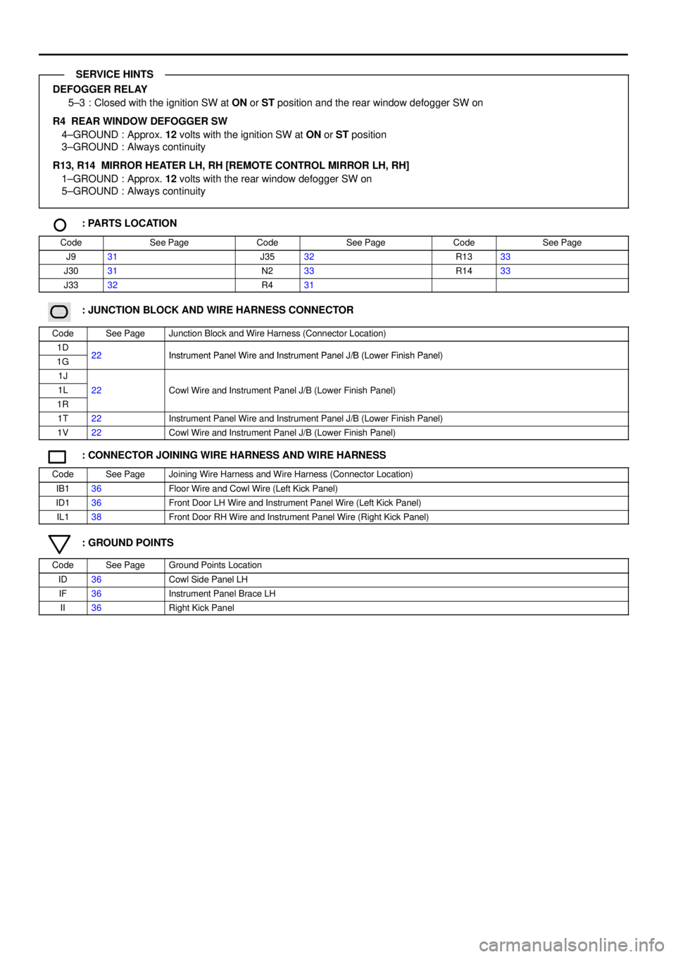
DEFOGGER RELAY
5±3 : Closed with the ignition SW at ON or ST position and the rear window defogger SW on
R4 REAR WINDOW DEFOGGER SW
4±GROUND : Approx. 12 volts with the ignition SW at ON or ST position
3±GROUND : Always continuity
R13, R14 MIRROR HEATER LH, RH [REMOTE CONTROL MIRROR LH, RH]
1±GROUND : Approx. 12 volts with the rear window defogger SW on
5±GROUND : Always continuity
: PARTS LOCATION
CodeSee PageCodeSee PageCodeSee Page
J931J3532R1333
J3031N233R1433
J3332R431
������ ���: JUNCTION BLOCK AND WIRE HARNESS CONNECTOR
CodeSee PageJunction Block and Wire Harness (Connector Location)
1D22Instrument Panel Wire and Instrument Panel J/B (Lower Finish Panel)1G22Instrument Panel Wire and Instrument Panel J/B (Lower Finish Panel)
1J
1L22Cowl Wire and Instrument Panel J/B (Lower Finish Panel)
1R
()
1T22Instrument Panel Wire and Instrument Panel J/B (Lower Finish Panel)
1V22Cowl Wire and Instrument Panel J/B (Lower Finish Panel)
: CONNECTOR JOINING WIRE HARNESS AND WIRE HARNESS
CodeSee PageJoining Wire Harness and Wire Harness (Connector Location)
IB136Floor Wire and Cowl Wire (Left Kick Panel)
ID136Front Door LH Wire and Instrument Panel Wire (Left Kick Panel)
IL138Front Door RH Wire and Instrument Panel Wire (Right Kick Panel)
: GROUND POINTS
CodeSee PageGround Points Location
ID36Cowl Side Panel LH
IF36Instrument Panel Brace LH
II36Right Kick Panel
SERVICE HINTS
Page 4155 of 4592
AIR CONDITIONING
1 1
11 1
12
3584
IF EB215
4
23
1 HI M2 M11W 2
I 6L±B
B±W
L±B
B±WL±W W±B
W±BL±R W±B
L±W
10A
HEATER
1
HTR
RELAY
BLOWER RESISTOR
BLOWER
MOTOR
B±W
L±B
L±O
BLOWER SWOFF FROM POWER SOURCE SYSTEM (
SEE PAGE 44)
LO B 2B 3
B 412
1 1 EB131R 3
2C 92K 5
23 1511
11A
AAA
3
JUNCTION
CONNECTOR J 9JUNCTION
CONNECTOR J30 FUSIBLE
LINK BLOCK F13
L±R
L±B L±B
L±B L±B
B±WL±Y B±W
L±B
L±B L±B
L±RTO FAN NO. 3 RELAY MG CLT
RELAY
10A A/C
EB2 1EB12
L±R
W±B
L±B
W± B
W±BL±B W±BL±RL±Y B±WL±B
W±B
50A HTR
A
I 3 W±B 61 M
Page 4156 of 4592
M
CONTROL
CIRCUIT
AIR VENT MODE CONTROL SERVO MOTOR A15IJ27 4 5 6 7 8 1 2 3
DD
12345
25 1
6
7D
A/C SW A12 JUNCTION
CONNECTOR J12 L±B
B±W
L±R
W± B
L±B
W± B
L±OB±L L±RL L±W W±BR±BL±R
GND FACE B/L FOOT F/D DEFDEF F/D
FOOT B/L FACE HEATER CONTROL SW H 7
L±Y B±WL±B
R±B
R±B
R±W
R±BL±R
OFF
ON DEF F/ D FOOT B/L FACE
IG
GNDL±R L±YL±Y
B A
Page 4158 of 4592

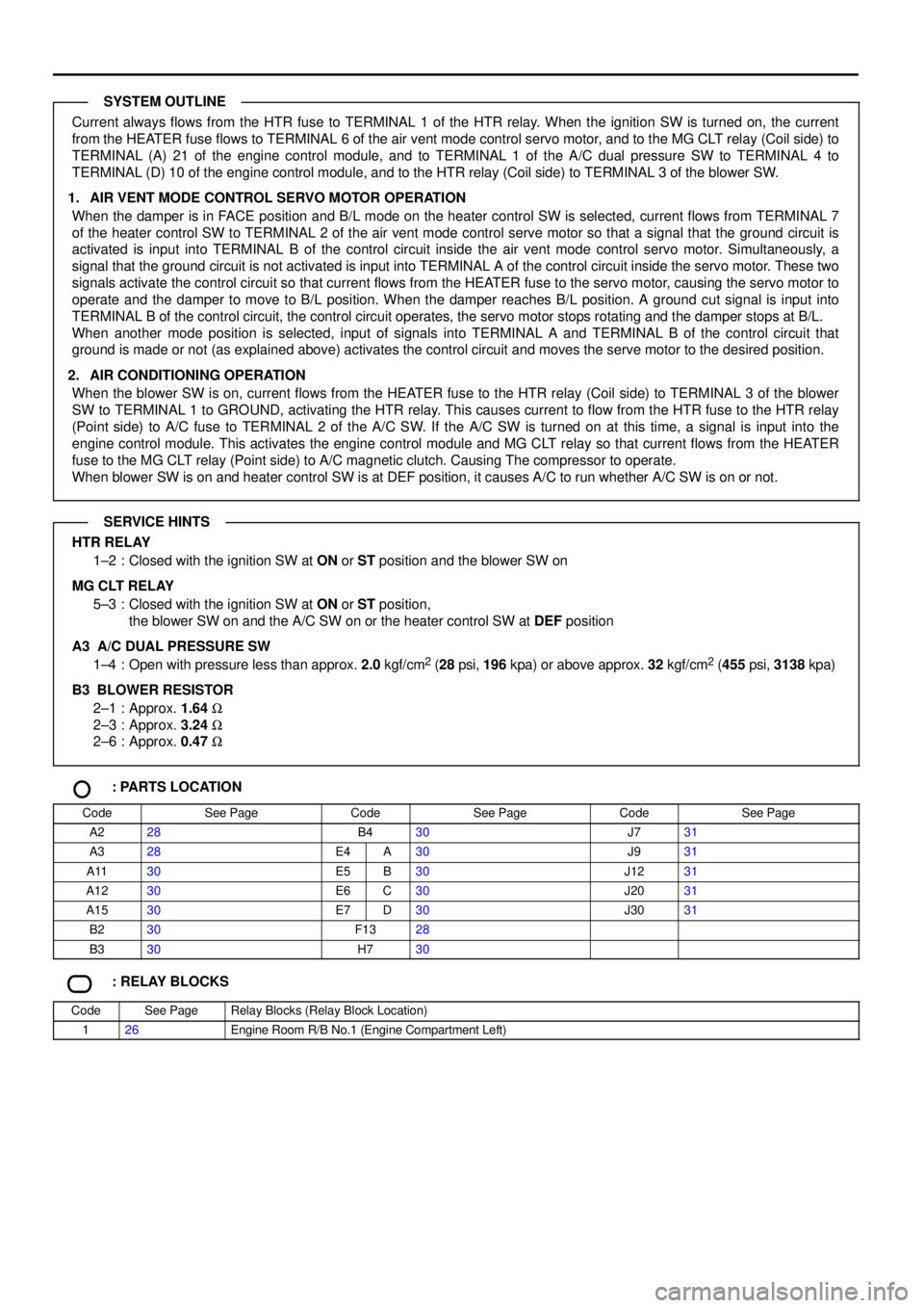
Current always flows from the HTR fuse to TERMINAL 1 of the HTR relay. When the ignition SW is turned on, the current
from the HEATER fuse flows to TERMINAL 6 of the air vent mode control servo motor, and to the MG CLT relay (Coil side) to
TERMINAL (A) 21 of the engine control module, and to TERMINAL 1 of the A/C dual pressure SW to TERMINAL 4 to
TERMINAL (D) 10 of the engine control module, and to the HTR relay (Coil side) to TERMINAL 3 of the blower SW.
1. AIR VENT MODE CONTROL SERVO MOTOR OPERATION
When the damper is in FACE position and B/L mode on the heater control SW is selected, current flows from TERMINAL 7
of the heater control SW to TERMINAL 2 of the air vent mode control serve motor so that a signal that the ground circuit is
activated is input into TERMINAL B of the control circuit inside the air vent mode control servo motor. Simultaneously, a
signal that the ground circuit is not activated is input into TERMINAL A of the control circuit inside the servo motor. These two
signals activate the control circuit so that current flows from the HEATER fuse to the servo motor, causing the servo motor to
operate and the damper to move to B/L position. When the damper reaches B/L position. A ground cut signal is input into
TERMINAL B of the control circuit, the control circuit operates, the servo motor stops rotating and the damper stops at B/L.
When another mode position is selected, input of signals into TERMINAL A and TERMINAL B of the control circuit that
ground is made or not (as explained above) activates the control circuit and moves the serve motor to the desired position.
2. AIR CONDITIONING OPERATION
When the blower SW is on, current flows from the HEATER fuse to the HTR relay (Coil side) to TERMINAL 3 of the blower
SW to TERMINAL 1 to GROUND, activating the HTR relay. This causes current to flow from the HTR fuse to the HTR relay
(Point side) to A/C fuse to TERMINAL 2 of the A/C SW. If the A/C SW is turned on at this time, a signal is input into the
engine control module. This activates the engine control module and MG CLT relay so that current flows from the HEATER
fuse to the MG CLT relay (Point side) to A/C magnetic clutch. Causing The compressor to operate.
When blower SW is on and heater control SW is at DEF position, it causes A/C to run whether A/C SW is on or not.
HTR RELAY
1±2 : Closed with the ignition SW at ON or ST position and the blower SW on
MG CLT RELAY
5±3 : Closed with the ignition SW at ON or ST position,
the blower SW on and the A/C SW on or the heater control SW at DEF position
A3 A/C DUAL PRESSURE SW
1±4 : Open with pressure less than approx. 2.0 kgf/cm
2 (28 psi, 196 kpa) or above approx. 32 kgf/cm2 (455 psi, 3138 kpa)
B3
BLOWER RESISTOR
2±1 : Approx. 1.64 W
2±3 : Approx. 3.24 W
2±6 : Approx. 0.47 W
: PARTS LOCATION
CodeSee PageCodeSee PageCodeSee Page
A228B430J731
A328E4A30J931
A1130E5B30J1231
A1230E6C30J2031
A1530E7D30J3031
B230F1328
B330H730
: RELAY BLOCKS
CodeSee PageRelay Blocks (Relay Block Location)
126Engine Room R/B No.1 (Engine Compartment Left)
SYSTEM OUTLINE
SERVICE HINTS
Page 4163 of 4592
![TOYOTA CAMRY 1999 Service Repair Manual I GROUND POINT
2K 1J CRUISE CONTROL
ECU
DATA LINK
CONNECTOR 3
POWER RELAY
INTEGRATION RELAY
NOISE FILTER CRUISE CONTROL
ACTUATOR
CRUISE CONTROL SW
[COMB. SW]
LIGHT CONTROL AND
DIMMER SW
[COMB. SW]
TOYOTA CAMRY 1999 Service Repair Manual I GROUND POINT
2K 1J CRUISE CONTROL
ECU
DATA LINK
CONNECTOR 3
POWER RELAY
INTEGRATION RELAY
NOISE FILTER CRUISE CONTROL
ACTUATOR
CRUISE CONTROL SW
[COMB. SW]
LIGHT CONTROL AND
DIMMER SW
[COMB. SW]](/manual-img/14/57448/w960_57448-4162.png)
I GROUND POINT
2K 1J CRUISE CONTROL
ECU
DATA LINK
CONNECTOR 3
POWER RELAY
INTEGRATION RELAY
NOISE FILTER CRUISE CONTROL
ACTUATOR
CRUISE CONTROL SW
[COMB. SW]
LIGHT CONTROL AND
DIMMER SW
[COMB. SW]
KEY INTERLOCK
SOLENOID
UNLOCK WARNING SW
CENTER AIRBAG
SENSOR ASSEMBLY
BRAKE FLUID LEVEL
WARNING SW
BLOWER SW BLOWER RESISTOR
REAR WINDOW
DEFOGGER SW
CI GARETTE LI GHTERWIPER AND WASHER
SW [COMB. SW]
ST RELAY
CENTER AIRBAG
SENSOR
ASSEMBLY
POWER OUTLETA A
A A
A A
A A
A A B A
B A
1J 81M31N1
A A
A
A
A
9
A A
1N3
1V41G 7
1V 3ID1 20
IF ID IHNOISE FILTER W±B
W±B
W±B W±B W±B W±B
W±B W±B
7
W±B
W±B
W± BW±B
W±B
W± B
W± B
JUNCTION
CONNECTOR J 9
W±B W±B
(
CG)
(
E1)
W±B
W±B
W±B
W±B
W± B
J 6
JUNCTION
CONNECTORB A, J 7
DOOR LOCK MOTOR
AND DOOR UNLOCK
DETECTION SW
FRONT L H
DOOR KEY LOCK AND
UNLOCK SW FRONT LH
MIRROR HEATER LH
[REMOTE CONTROL
MIRROR LH]W±B
W±B
W±B
HEATER CONTROL SW
AIR VENT MODE
CONTROL SERVO MOTOR I 3W± B W± B
W±B
ABS ECU AW±B
W±B W±B
A
(
E2)TURN SIGNAL FLASHER
A
W±B
(
GND)
(
GND)
JUNCTION CONNECTOR J33
A W±B
W±BW± B
POWER WINDOW
MASTER SWA
W±B