Page 3381 of 4592
SF0EC±04
B06365
Ohmmeter
+B
HT
± SFI (5S±FE)AIR±FUEL RATIO (A/F) SENSOR (California)
SF±59
1492 Author�: Date�:
INSPECTION
1. INSPECT HEATER RESISTANCE OF A/F SENSOR
(a) Disconnect the A/F sensor connector.
(b) Using an ohmmeter, measure the resistance between ter-
minals +B and HT.
Resistance: 0.8 ± 1.4 W at 20°C (68°F)
If the resistance is not as specified, replace the sensor.
Torque: 44 N´m (450 kgf´cm, 32 ft´lbf)
(c) Reconnect the A/F sensor connector.
2. INSPECT OPERATION OF A/F SENSOR
(See page DI±152)
Page 3383 of 4592
SF0EI±03
B06363
Ohmmeter
HT
+B
± SFI (5S±FE)HEATED OXYGEN SENSOR (Bank 1 Sensor 1/Except
Calif.)SF±61
1494 Author�: Date�:
INSPECTION
1. INSPECT HEATER RESISTANCE OF HEATED OXY-
GEN SENSOR
(a) Disconnect the oxygen sensor connector.
(b) Using an ohmmeter, measure the resistance between ter-
minals +B and HT.
Resistance: 11 ± 16 W at 20°C (68°F)
If the resistance is not as specified, replace the sensor.
Torque: 44 N´m (450 kgf´cm, 32 ft´lbf)
(c) Reconnect the oxygen sensor connector.
2. INSPECT OPERATION OF HEATED OXYGEN SEN-
SOR (See page DI±66)
Page 3385 of 4592
SF0EK±03
S05303
Ohmmeter
HT +B
± SFI (5S±FE)HEATED OXYGEN SENSOR (Bank 1 Sensor 2)
SF±63
1496 Author�: Date�:
INSPECTION
1. INSPECT HEATER RESISTANCE OF HEATED OXY-
GEN SENSOR
(a) Disconnect the oxygen sensor connector.
(b) Using an ohmmeter, measure the resistance between ter-
minals +B and HT.
Resistance: 11 ± 16 W at 20°C (68°F)
If the resistance is not as specified, replace the sensor.
Torque: 44 N´m (450 kgf´cm, 32 ft´lbf)
(c) Reconnect the oxygen sensor connector.
2. INSPECT OPERATION OF HEATED OXYGEN SEN-
SOR (See page DI±75)
Page 3457 of 4592

SF08K±03
B06390
VSV Connector for
EVAP
Ground Cable
PCV Hose
Air Intake Chamber
Assembly
ECT Sensor
Connector ECT Sender
Gauge ConnectorEGR Valve Position
Sensor Connector
IAC Valve
Connector
VSV Connector
for EGR
VSV Connector for ACIS
Engine Wire
Engine Coolant
Reservoir HoseAir Assist Hose
Water Bypass Hose No.2 EGR Pipe
Throttle Position
Sensor Connector
No.1 Engine
HangerBrake Booster
Vacuum Hose Air Intake Chamber Stay
Water OutletPS Pressure Tube
�Gasket
19.5 (200, 14)
39 (400, 19)12 (120, 19)
15 (150, 11)
�Gasket
43 (440, 32)
Ground Starp
DLC1
�Gasket
15 (150, 11)
Grand Strap
Connector
�Gasket
39 (400, 29)
V±Bank Cover
Accelerator Cable
Throttle Cable
Air Cleaner
Hose
Purge HoseEGR Gas Temperature
Sensor Connector
Vacuum
HoseWater Bypass Hose
Fuel Inlet Hose
Heater Hose
Intake Manifold Assembly
Injector Connector x 9
Knock Sensor
Connector
Upper Radiator
Hose
Engine
Wire
Band
High±Tension Cord
Set �Gasket
: Specified torque
�Non±reusable partN´m (kgf´cm, ft´lbf)
�Retainer
Knock Sensor
SF±66
± SFI (1MZ±FE)KNOCK SENSOR
1565 Author�: Date�:
KNOCK SENSOR
COMPONENTS
Page 3459 of 4592
S05042
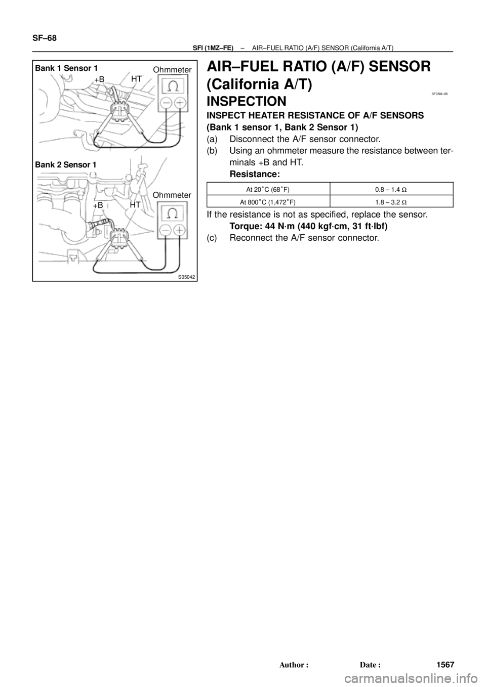
Bank 1 Sensor 1
Bank 2 Sensor 1
Ohmmeter +BHT
+BHTOhmmeter
SF08M±06
SF±68
± SFI (1MZ±FE)AIR±FUEL RATIO (A/F) SENSOR (California A/T)
1567 Author�: Date�:
AIR±FUEL RATIO (A/F) SENSOR
(California A/T)
INSPECTION
INSPECT HEATER RESISTANCE OF A/F SENSORS
(Bank 1 sensor 1, Bank 2 Sensor 1)
(a) Disconnect the A/F sensor connector.
(b) Using an ohmmeter measure the resistance between ter-
minals +B and HT.
Resistance:
At 20°C (68°F)0.8 ± 1.4 W
At 800°C (1,472°F)1.8 ± 3.2 W
If the resistance is not as specified, replace the sensor.
Torque: 44 N´m (440 kgf´cm, 31 ft´lbf)
(c) Reconnect the A/F sensor connector.
Page 3462 of 4592
S05042
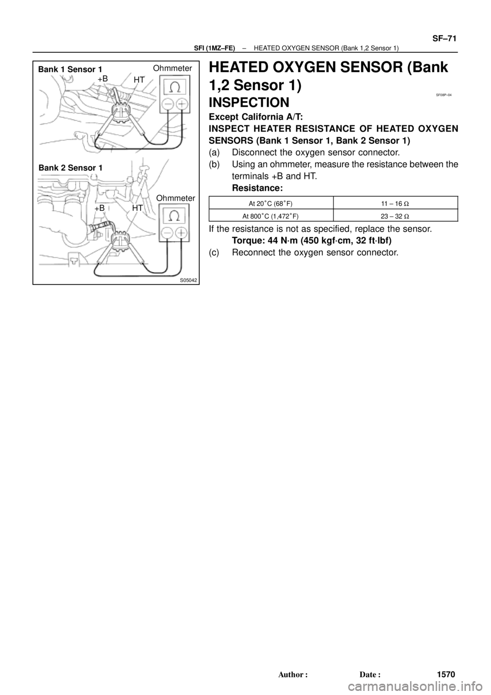
Bank 1 Sensor 1
Bank 2 Sensor 1+B
HTOhmmeter
+B HTOhmmeter
SF08P±04
± SFI (1MZ±FE)HEATED OXYGEN SENSOR (Bank 1,2 Sensor 1)
SF±71
1570 Author�: Date�:
HEATED OXYGEN SENSOR (Bank
1,2 Sensor 1)
INSPECTION
Except California A/T:
INSPECT HEATER RESISTANCE OF HEATED OXYGEN
SENSORS (Bank 1 Sensor 1, Bank 2 Sensor 1)
(a) Disconnect the oxygen sensor connector.
(b) Using an ohmmeter, measure the resistance between the
terminals +B and HT.
Resistance:
At 20°C (68°F)11 ± 16 W
At 800°C (1,472°F)23 ± 32 W
If the resistance is not as specified, replace the sensor.
Torque: 44 N´m (450 kgf´cm, 32 ft´lbf)
(c) Reconnect the oxygen sensor connector.
Page 3463 of 4592
S05163
Ohmmeter
+B
HTSF08Q±03
SF±72
± SFI (1MZ±FE)HEATED OXYGEN SENSOR (Bank 1 Sensor 2)
1571 Author�: Date�:
HEATED OXYGEN SENSOR (Bank
1 Sensor 2)
INSPECTION
INSPECT HEATER RESISTANCE OF HEATED OXYGEN
SENSOR (Bank 1 Sensor 2)
(a) Remove the driver's seat.
(b) Take out the floor carpet.
(c) Disconnect the oxygen sensor connector.
(d) Using an ohmmeter, measure the resistance between the
terminals +B and HT.
Resistance:
At 20°C (68°F)11 ± 16 W
At 800°C (1,472°F)23 ± 32 W
If the resistance is not as specified, replace the sensor.
(e) Reconnect the oxygen sensor connector.
Torque: 44 N´m (450 kgf´cm, 32 ft´lbf)
(f) Reinstall the floor carpet.
(g) Reinstall the driver's seat.
Page 3771 of 4592

Toyota Supports ASE CertificationPage 1 of 23
EG003-02Title:
READINESS MONITOR DRIVE PATTERNS
Models:
All '96 ± '02
Technical Service
BULLETIN
March 29, 2002
TSB REVISION NOTICE:
The information updated in this TSB is red
and underlined.
The On±Board Diagnostic (OBDII) system is designed to monitor the performance of
emission±related components and report any detected abnormalities in the form of
Diagnostic Trouble Codes (DTCs). Since the various components need to be monitored
during different driving conditions, the OBDII system is designed to run separate
monitoring programs called Readiness Monitors. Many state Inspection and
Maintenance (I/M) programs require that vehicles complete their Readiness Monitors
prior to beginning an emissions test.
The current status of the Readiness Monitors can be seen by using the Toyota Diagnostic
Tester with version 9.0 software (or newer), or a generic OBDII Scantool.
To view the Readiness Monitor status using the Toyota Diagnostic Tester, select ªMonitor
Statusº from the Enhanced OBDII Menu.
A status of ªcompleteº indicates that the necessary conditions have been met to run the
performance tests for the related Readiness Monitor.
The Readiness Monitor will be reset to ªincompleteº if:
�ECU has lost power (battery or fuse).
�DTCs have been cleared.
�The conditions for running the Readiness Monitor have not been met.
In the event that any Readiness Monitor shows ªincomplete,º follow the appropriate
Readiness Monitor Drive Pattern to change the readiness status to ªcomplete.º
Refer to the Readiness Monitor Drive Pattern Application Table to determine which
drive pattern should be followed.
SECTIONPAGE(S)
Readiness Monitor Drive Pattern Application Tables3±9
Readiness Monitor Drive Patterns
1EGR Monitor (All Except 1FZ±FE Engine)10
2EGR Monitor (For 1FZ±FE Engine)11
3Catalyst Monitor (O2S Type)12
4Catalyst Monitor (AF Sensor Type)13
5EVAP Monitor (Internal Pressure Monitor/Non±Intrusive Type)14±15
6EVAP Monitor (Vacuum Pressure Monitor/Intrusive Type)16±17
7EVAP Monitor (Without Leak Detection)18
8EVAP Monitor (For Prius)19±20
9Oxygen Sensor Monitor (Front and Rear O2S System)21
10Oxygen/AF Sensor Monitor (Front AF Sensor and Rear O2S System)22
11Oxygen/AF Sensor Heater Monitor23
�All 1996 ± 2002 model year Toyota vehicles.
OP CODEDESCRIPTIONTIMEOPNT1T2
N/ANot Applicable to Warranty±±±±
ENGINE
Introduction
Contents
Applicable
Vehicles
Warranty
Information