Page 519 of 1456

3) Install transfer case with extension assembly to
transmission case.
Tightening torque:
24.5
±2.0 N´m (2.50±0.20 kg-m, 18.1±1.4
ft-lb)
B3M1373
E: ADJUSTMENT
1. NEUTRAL POSITION ADJUSTMENT
1) Shift gear into 3rd gear position.
2) Shifter arm turns lightly toward the 1st/2nd gear
side but heavily toward the reverse gear side
because of the function of the return spring, until
arm contacts the stopper.
3) Make adjustment so that the heavy stroke
(reverse side) is a little more than the light stroke
(1st/2nd side).
4) To adjust, remove bolts holding reverse check
sleeve assembly to the case, move sleeve assem-
bly outward, and place adjustment shim (0 to 1 ea.)
between sleeve assembly and case to adjust the
clearance.
CAUTION:
Be careful not to break O-ring when placing
shim(s).
NOTE:
IWhen shim is removed, the neutral position will
move closer to reverse; when shim is added, the
neutral position will move closer to 1st gear.
IIf shims alone cannot adjust the clearance,
replace reverse accent shaft and re-adjust.
Adjustment shim
Part No. Thickness mm (in)
32190AA000 0.15 (0.0059)
32190AA010 0.30 (0.0118)
Reverse accent shaft
Part No. Mark Remarks
32188AA090 XNeutral position is
closer to 1st gear.
32188AA100 Y Standard
32188AA110 ZNeutral position is
closer to reverse gear.
2. REVERSE CHECK PLATE
ADJUSTMENT
1) Shift shifter arm to ª5thº and then to reverse to
see if reverse check mechanism operates properly.
2) Also check to see if arm returns to neutral when
released from the reverse position. If arm does not
return properly, replace reverse check plate.
Reverse check plate
Part No. (A): No. AngleqRemarks
32189AA000 0 28ÉArm stops closer to
5th gear.
32189AA010 1 31ÉArm stops closer to
5th gear.
32189AA020 2 34ÉArm stops in the cen-
ter.
32189AA030 3 37ÉArm stops closer to
reverse gear.
32189AA040 4 40ÉArm stops closer to
reverse gear.
B3M0054B
3) Install neutral position switch and back-up light
switch to transfer case.
Tightening torque:
24.5
±2.0 N´m (2.50±0.20 kg-m, 18.1±1.4
ft-lb)
B3M1372A
48
3-1[W5E1]SERVICE PROCEDURE
5. Transfer Case and Extension
Page 555 of 1456

2. Inhibitor Switch
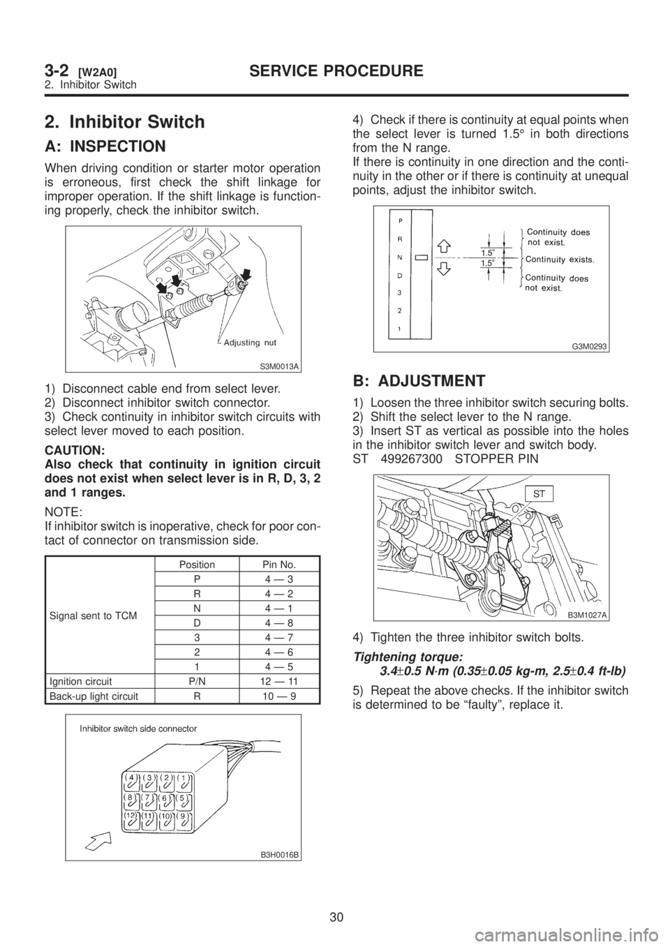
A: INSPECTION
When driving condition or starter motor operation
is erroneous, first check the shift linkage for
improper operation. If the shift linkage is function-
ing properly, check the inhibitor switch.
S3M0013A
1) Disconnect cable end from select lever.
2) Disconnect inhibitor switch connector.
3) Check continuity in inhibitor switch circuits with
select lever moved to each position.
CAUTION:
Also check that continuity in ignition circuit
does not exist when select lever is in R, D, 3, 2
and 1 ranges.
NOTE:
If inhibitor switch is inoperative, check for poor con-
tact of connector on transmission side.
Signal sent to TCMPosition Pin No.
P 4Ð3
R 4Ð2
N 4Ð1
D 4Ð8
3 4Ð7
2 4Ð6
1 4Ð5
Ignition circuit P/N 12 Ð 11
Back-up light circuit R 10 Ð 9
B3H0016B
4) Check if there is continuity at equal points when
the select lever is turned 1.5É in both directions
from the N range.
If there is continuity in one direction and the conti-
nuity in the other or if there is continuity at unequal
points, adjust the inhibitor switch.
G3M0293
B: ADJUSTMENT
1) Loosen the three inhibitor switch securing bolts.
2) Shift the select lever to the N range.
3) Insert ST as vertical as possible into the holes
in the inhibitor switch lever and switch body.
ST 499267300 STOPPER PIN
B3M1027A
4) Tighten the three inhibitor switch bolts.
Tightening torque:
3.4
±0.5 N´m (0.35±0.05 kg-m, 2.5±0.4 ft-lb)
5) Repeat the above checks. If the inhibitor switch
is determined to be ªfaultyº, replace it.
30
3-2[W2A0]SERVICE PROCEDURE
2. Inhibitor Switch
Page 564 of 1456
7) Remove rear crossmember.
(1) Support transmission using a transmission
jack and raise slightly.
(2) Remove bolts and nuts as shown in Figure.
S2M0221
8) Remove vehicle speed sensor 1 (rear).
B3M1043
9) Remove extension and gasket.
(1) Remove select cable nut.
G3M0308
(2) Move gear select cable so that extension
bolts can be removed.
(3) Remove bolts.(4) Remove extension case.
NOTE:
Use a container to catch oil flowing from extension.
B3M1044
10) Disconnect duty solenoid C (transfer) connec-
tor.
11) Remove duty solenoid C (transfer) and trans-
fer valve body.
B3M1045A
B: INSTALLATION
1) Install duty solenoid C and transfer valve body.
(1) Install duty solenoid C and transfer valve
body.
Tightening torque:
T: 8
±1 N´m (0.8±0.1 kg-m, 5.8±0.7 ft-lb)
(2) Connect duty solenoid C (transfer) connec-
tor.
B3M1045B
38
3-2[W5B0]SERVICE PROCEDURE
5. Duty Solenoid C and Transfer Valve Body
Page 577 of 1456

10) Remove the oil cooler inlet and outlet pipes.
CAUTION:
When removing outlet pipes, be careful not to
lose balls and springs used with retaining
screws.
B3M1053A
2. SEPARATION OF EACH SECTION
1) Separation of torque converter clutch case and
transmission case sections
CAUTION:
IBe careful not to damage the oil seal and
bushing inside the torque converter clutch
case by the oil pump cover.
IBe careful not to lose the rubber seal.
NOTE:
Separate these cases while tapping lightly on the
housing.
B3M1055A
2) Separation of transmission case and extension
sections
(1) Remove vehicle speed sensor 1 (rear).
B3M1056A
(2) Separation of transmission case and exten-
sion case sections
B3M1057A
3. TRANSMISSION CASE SECTION
1) Remove the reduction driven gear.
(1) Straighten the staked portion, and remove
the lock nut.
NOTE:
Set the range selector lever to ªPº.
B3M1058A
(2) Using the ST1 and ST2, extract the reduc-
tion driven gear.
NOTE:
ST1 499737000 PULLER
ST2 899524100 PULLER SET
B3M0954A
48
3-2[W11B2]SERVICE PROCEDURE
11. Overall Transmission
Page 583 of 1456

34) Remove parking support.
B3M1088A
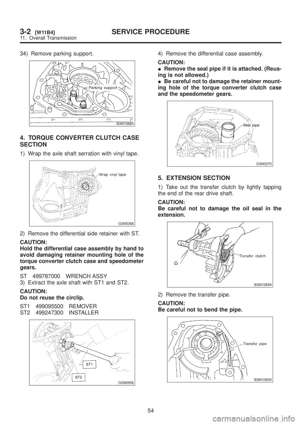
4. TORQUE CONVERTER CLUTCH CASE
SECTION
1) Wrap the axle shaft serration with vinyl tape.
G3M0368
2) Remove the differential side retainer with ST.
CAUTION:
Hold the differential case assembly by hand to
avoid damaging retainer mounting hole of the
torque converter clutch case and speedometer
gears.
ST 499787000 WRENCH ASSY
3) Extract the axle shaft with ST1 and ST2.
CAUTION:
Do not reuse the circlip.
ST1 499095500 REMOVER
ST2 499247300 INSTALLER
G3M0956
4) Remove the differential case assembly.
CAUTION:
IRemove the seal pipe if it is attached. (Reus-
ing is not allowed.)
IBe careful not to damage the retainer mount-
ing hole of the torque converter clutch case
and the speedometer gears.
G3M0370
5. EXTENSION SECTION
1) Take out the transfer clutch by lightly tapping
the end of the rear drive shaft.
CAUTION:
Be careful not to damage the oil seal in the
extension.
B3M1089A
2) Remove the transfer pipe.
CAUTION:
Be careful not to bend the pipe.
B3M1090A
54
3-2[W11B4]SERVICE PROCEDURE
11. Overall Transmission
Page 584 of 1456

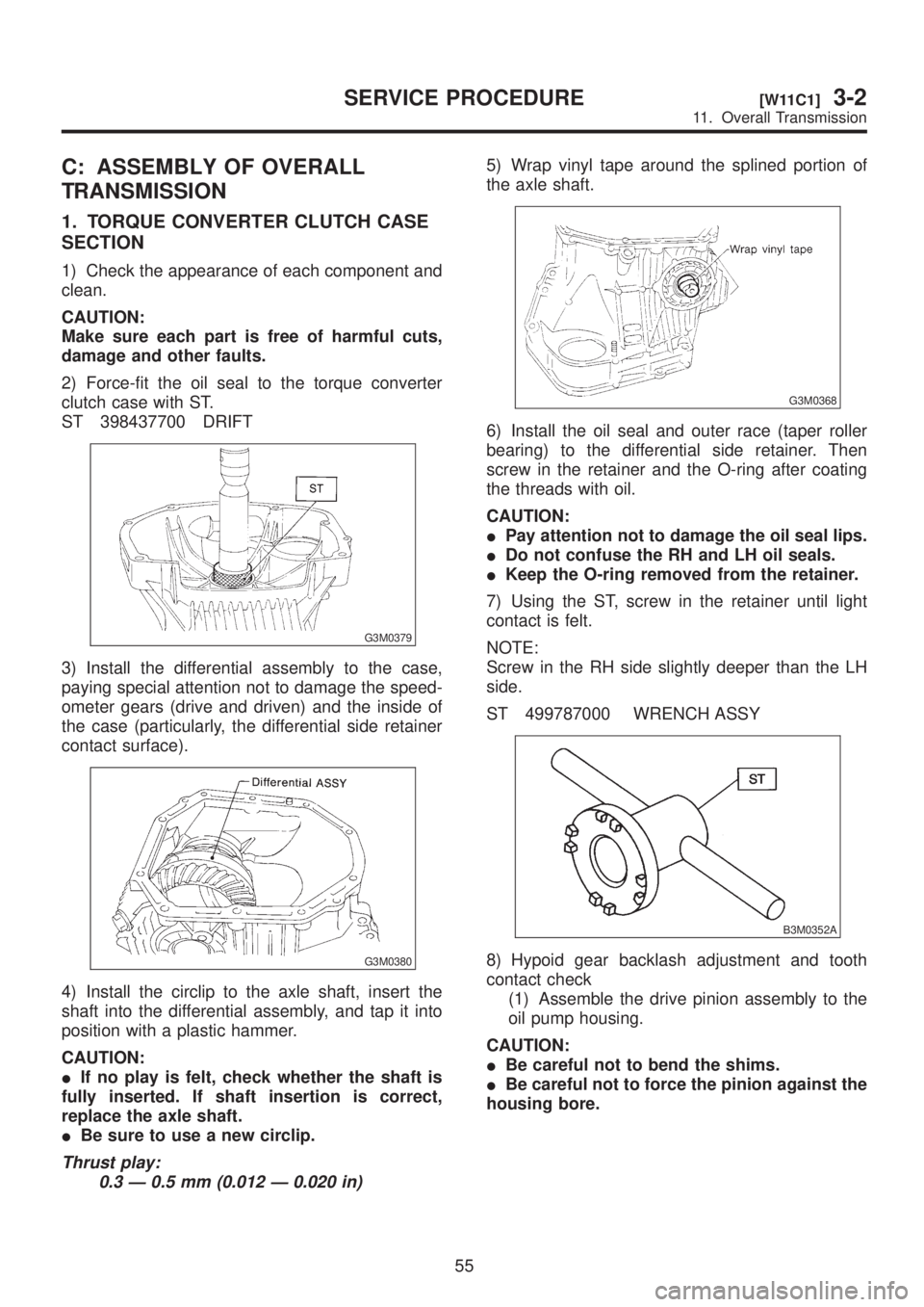
C: ASSEMBLY OF OVERALL
TRANSMISSION
1. TORQUE CONVERTER CLUTCH CASE
SECTION
1) Check the appearance of each component and
clean.
CAUTION:
Make sure each part is free of harmful cuts,
damage and other faults.
2) Force-fit the oil seal to the torque converter
clutch case with ST.
ST 398437700 DRIFT
G3M0379
3) Install the differential assembly to the case,
paying special attention not to damage the speed-
ometer gears (drive and driven) and the inside of
the case (particularly, the differential side retainer
contact surface).
G3M0380
4) Install the circlip to the axle shaft, insert the
shaft into the differential assembly, and tap it into
position with a plastic hammer.
CAUTION:
IIf no play is felt, check whether the shaft is
fully inserted. If shaft insertion is correct,
replace the axle shaft.
IBe sure to use a new circlip.
Thrust play:
0.3 Ð 0.5 mm (0.012 Ð 0.020 in)
5) Wrap vinyl tape around the splined portion of
the axle shaft.
G3M0368
6) Install the oil seal and outer race (taper roller
bearing) to the differential side retainer. Then
screw in the retainer and the O-ring after coating
the threads with oil.
CAUTION:
IPay attention not to damage the oil seal lips.
IDo not confuse the RH and LH oil seals.
IKeep the O-ring removed from the retainer.
7) Using the ST, screw in the retainer until light
contact is felt.
NOTE:
Screw in the RH side slightly deeper than the LH
side.
ST 499787000 WRENCH ASSY
B3M0352A
8) Hypoid gear backlash adjustment and tooth
contact check
(1) Assemble the drive pinion assembly to the
oil pump housing.
CAUTION:
IBe careful not to bend the shims.
IBe careful not to force the pinion against the
housing bore.
55
[W11C1]3-2SERVICE PROCEDURE
11. Overall Transmission
Page 587 of 1456
![SUBARU LEGACY 1999 Service Repair Manual Checking item Contact pattern Corrective action
Tooth contact
Tooth contact pattern is slightly shifted
toward to under no-load rotation.
[When loaded, contact pattern moves
toward heel.]
B3M0317A
Ð
SUBARU LEGACY 1999 Service Repair Manual Checking item Contact pattern Corrective action
Tooth contact
Tooth contact pattern is slightly shifted
toward to under no-load rotation.
[When loaded, contact pattern moves
toward heel.]
B3M0317A
Ð](/manual-img/17/57435/w960_57435-586.png)
Checking item Contact pattern Corrective action
Tooth contact
Tooth contact pattern is slightly shifted
toward to under no-load rotation.
[When loaded, contact pattern moves
toward heel.]
B3M0317A
Ð
Face contact
Backlash is too large.This may cause noise and chipping at
tooth ends.
B3M0319
Increase thickness of drive pinion height
adjusting shim in order to bring drive pin-
ion close to crown gear.
B3M0323
Flank contact Backlash is too small. This may cause noise and stepped wear
on surfaces.
B3M0320
Reduce thickness of drive pinion height
adjusting shim in order to move drive
pinion away from crown gear.
B3M0324
Toe contact
(Inside end contact)
Contact areas is small.This may cause chipping at toe.
B3M0321
Adjust as for flank contact.
B3M0324
Heel contact (Outside end contact)
Contact area is small.This may cause chipping at heel ends.
B3M0322
Adjust as for face contact.
B3M0323
: Adjusting direction of drive pinion: Adjusting direction of crown gear
58
3-2[W11C1]SERVICE PROCEDURE
11. Overall Transmission
Page 601 of 1456

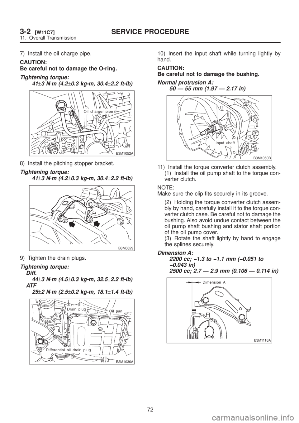
7) Install the oil charge pipe.
CAUTION:
Be careful not to damage the O-ring.
Tightening torque:
41
±3 N´m (4.2±0.3 kg-m, 30.4±2.2 ft-lb)
B3M1052A
8) Install the pitching stopper bracket.
Tightening torque:
41
±3 N´m (4.2±0.3 kg-m, 30.4±2.2 ft-lb)
B3M0629
9) Tighten the drain plugs.
Tightening torque:
Diff.
44
±3 N´m (4.5±0.3 kg-m, 32.5±2.2 ft-lb)
AT F
25
±2 N´m (2.5±0.2 kg-m, 18.1±1.4 ft-lb)
B3M1036A
10) Insert the input shaft while turning lightly by
hand.
CAUTION:
Be careful not to damage the bushing.
Normal protrusion A:
50 Ð 55 mm (1.97 Ð 2.17 in)
B3M1050B
11) Install the torque converter clutch assembly.
(1) Install the oil pump shaft to the torque con-
verter clutch.
NOTE:
Make sure the clip fits securely in its groove.
(2) Holding the torque converter clutch assem-
bly by hand, carefully install it to the torque con-
verter clutch case. Be careful not to damage the
bushing. Also avoid undue contact between the
oil pump shaft bushing and stator shaft portion
of the oil pump cover.
(3) Rotate the shaft lightly by hand to engage
the splines securely.
Dimension A:
2200 cc; þ1.3 to þ1.1 mm (þ0.051 to
þ0.043 in)
2500 cc; 2.7 Ð 2.9 mm (0.106 Ð 0.114 in)
B3M1116A
72
3-2[W11C7]SERVICE PROCEDURE
11. Overall Transmission