1999 SUBARU LEGACY height adjustment
[x] Cancel search: height adjustmentPage 595 of 1456

(2) Using ST, measure the distance from the oil
pump housing mating surface to the top surface
of the oil pump cover with thrust needle bearing.
ST 398643600 GAUGE
B3M0983A
(3) Calculation of total end play
Select suitable bearing race from among those
listed in this table so that clearance C is in the
0.25 Ð 0.55 mm (0.0098 Ð 0.0217 in) range.
C=(L+G)þ
CClearance between concave portion of high clutch
and end of clutch drum support
LLength from case mating surface to concave por-
tion of high clutch
G Gasket thickness (0.28 mm, 0.0110 in)
Height from housing mating surface to upper sur-
face of clutch drum support
B3M0984A
Thrust needle bearing
Part No. Thickness mm (in)
806528050
806528060
806528070
806528080
806528090
8065281004.1 (0.161)
4.3 (0.169)
4.5 (0.177)
4.7 (0.185)
4.9 (0.193)
5.1 (0.201)
27) Install the oil pump housing assembly.
(1) After completing end play adjustment, insert
the bearing race in the recess of the high clutch.
Attach the thrust needle bearing to the oil pump
cover with vaseline.(2) After correctly installing the gasket to the
case mating surface, carefully install the oil
pump housing assembly. Be careful to avoid hit-
ting the drive pinion against the inside of the
case.
CAUTION:
IBe careful not to damage the seal ring.
IBe sure to use a new gasket.
(3) Install both parts with dowel pins aligned.
Make sure no clearance exists at the mating
surface.
NOTE:
Any clearance suggests a damaged seal ring.
(4) Secure the housing with two nuts.
Tightening torque:
T: 4 1
±3 N´m (4.2±0.3 kg-m, 30.4±2.2 ft-lb)
B3M1068A
3. TORQUE CONVERTER CLUTCH CASE
AND TRANSMISSION CASE
1) Apply proper amount of liquid gasket (THREE
BOND Part No. 1215) to the entire torque con-
verter clutch case mating surface.
NOTE:
Make sure that the rubber seal and seal pipe are
fitted in position.
G3M0394
66
3-2[W11C3]SERVICE PROCEDURE
11. Overall Transmission
Page 681 of 1456

Replace if deformed or damaged, and at every
disassembling.
6) Differential carrier
Replace if the bearing bores are worn or damaged.
7) Differential case
Replace if its sliding surfaces are worn or cracked.
8) Companion flange
Replace if the oil seal lip contacting surfaces have
flaws.
E: ASSEMBLY
1. T-TYPE
1) Precautions for assembling
IAssemble in the reverse order of disassembling.
ICheck and adjust each part during assembly.
IKeep the shims and washers in order, so that
they are not misinstalled.
IThoroughly clean the surfaces on which the
shims, washers and bearings are to be installed.
IApply gear oil when installing the bearings and
thrust washers.
IBe careful not to mix up the right and left hand
races of the bearings.
IReplace the oil seal with new one at every dis-
assembly. Apply chassis grease between the lips
when installing the oil seal.
G3M0079
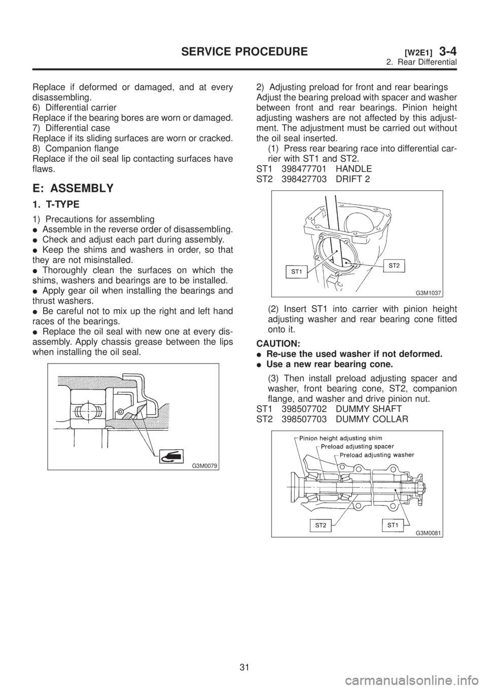
2) Adjusting preload for front and rear bearings
Adjust the bearing preload with spacer and washer
between front and rear bearings. Pinion height
adjusting washers are not affected by this adjust-
ment. The adjustment must be carried out without
the oil seal inserted.
(1) Press rear bearing race into differential car-
rier with ST1 and ST2.
ST1 398477701 HANDLE
ST2 398427703 DRIFT 2
G3M1037
(2) Insert ST1 into carrier with pinion height
adjusting washer and rear bearing cone fitted
onto it.
CAUTION:
IRe-use the used washer if not deformed.
IUse a new rear bearing cone.
(3) Then install preload adjusting spacer and
washer, front bearing cone, ST2, companion
flange, and washer and drive pinion nut.
ST1 398507702 DUMMY SHAFT
ST2 398507703 DUMMY COLLAR
G3M0081
31
[W2E1]3-4SERVICE PROCEDURE
2. Rear Differential
Page 687 of 1456

16) Check the crown gear runout on its back
surface, and make sure pinion and crown gear
rotate smoothly.
Limit of runout:
Less than 0.05 mm (0.0020 in)
G3M1048
17) Checking and adjusting tooth contact of crown
gear
(1) Apply an even coat of red lead on both
sides of three or four teeth on the crown gear.
Check the contact pattern after rotating crown
gear several revolutions back and forth until a
definite contact pattern appears on the crown
gear.
(2) When the contact pattern is incorrect, read-
just according to the instructions given in
ªTOOTH CONTACT PATTERNº.
NOTE:
Be sure to wipe off red lead completely after
adjustment is completed.
18) If proper tooth contact is not obtained, once
again adjust the drive pinion height, changing RH
and LH side bearing retainer shims and the hypoid
gear backlash.(1) Drive pinion height
ST1 398507702 DUMMY SHAFT
ST2 398507701 DIFFERENTIAL CARRIER
GAUGE
T=To+Nþ(Hx0.01) þ 0.20 (mm)
Where:
T = Thickness of pinion height adjusting shim
(mm)
To = Thickness of shim temporarily inserted
(mm)
N = Reading of thickness gauge (mm)
H = Figure marked on drive pinion head
H3M1309A
(2) Hypoid gear backlash
Backlash:
0.10 Ð 0.20 mm (0.0039 Ð 0.0079 in)
G3M1047
37
[W2E1]3-4SERVICE PROCEDURE
2. Rear Differential
Page 688 of 1456

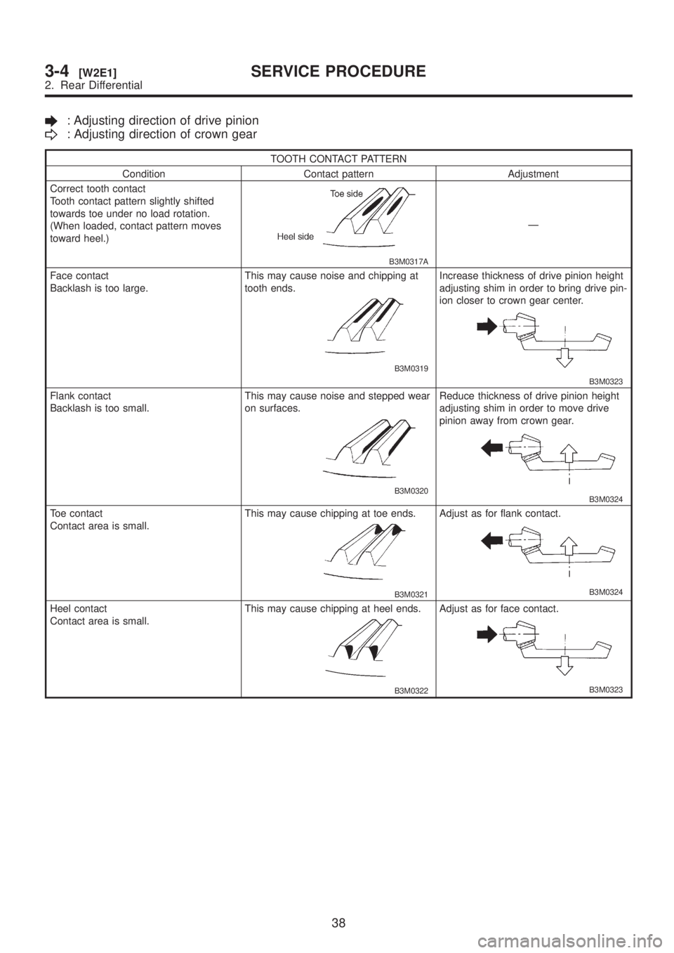
: Adjusting direction of drive pinion
: Adjusting direction of crown gear
TOOTH CONTACT PATTERN
Condition Contact pattern Adjustment
Correct tooth contact
Tooth contact pattern slightly shifted
towards toe under no load rotation.
(When loaded, contact pattern moves
toward heel.)
B3M0317A
Ð
Face contact
Backlash is too large.This may cause noise and chipping at
tooth ends.
B3M0319
Increase thickness of drive pinion height
adjusting shim in order to bring drive pin-
ion closer to crown gear center.
B3M0323
Flank contact
Backlash is too small.This may cause noise and stepped wear
on surfaces.
B3M0320
Reduce thickness of drive pinion height
adjusting shim in order to move drive
pinion away from crown gear.
B3M0324
Toe contact
Contact area is small.This may cause chipping at toe ends.
B3M0321
Adjust as for flank contact.
B3M0324
Heel contact
Contact area is small.This may cause chipping at heel ends.
B3M0322
Adjust as for face contact.
B3M0323
38
3-4[W2E1]SERVICE PROCEDURE
2. Rear Differential
Page 689 of 1456

19) Install rear cover and tighten bolts to specified
torque.
Tightening torque:
29
±5 N´m (3.0±0.5 kg-m, 21.7±3.6 ft-lb)
G3M1050
2. VA-TYPE
1) Precautions for assembling
IAssemble in the reverse order of disassembling.
ICheck and adjust each part during assembly.
IKeep the shims and washers in order, so that
they are not misinstalled.
IThoroughly clean the surfaces on which the
shims, washers and bearings are to be installed.
IApply gear oil when installing the bearings and
thrust washers.
IBe careful not to mix up the right and left hand
races of the bearings.
IReplace the oil seal with new one at every dis-
assembly. Apply chassis grease between the lips
when installing the oil seal.
G3M0079
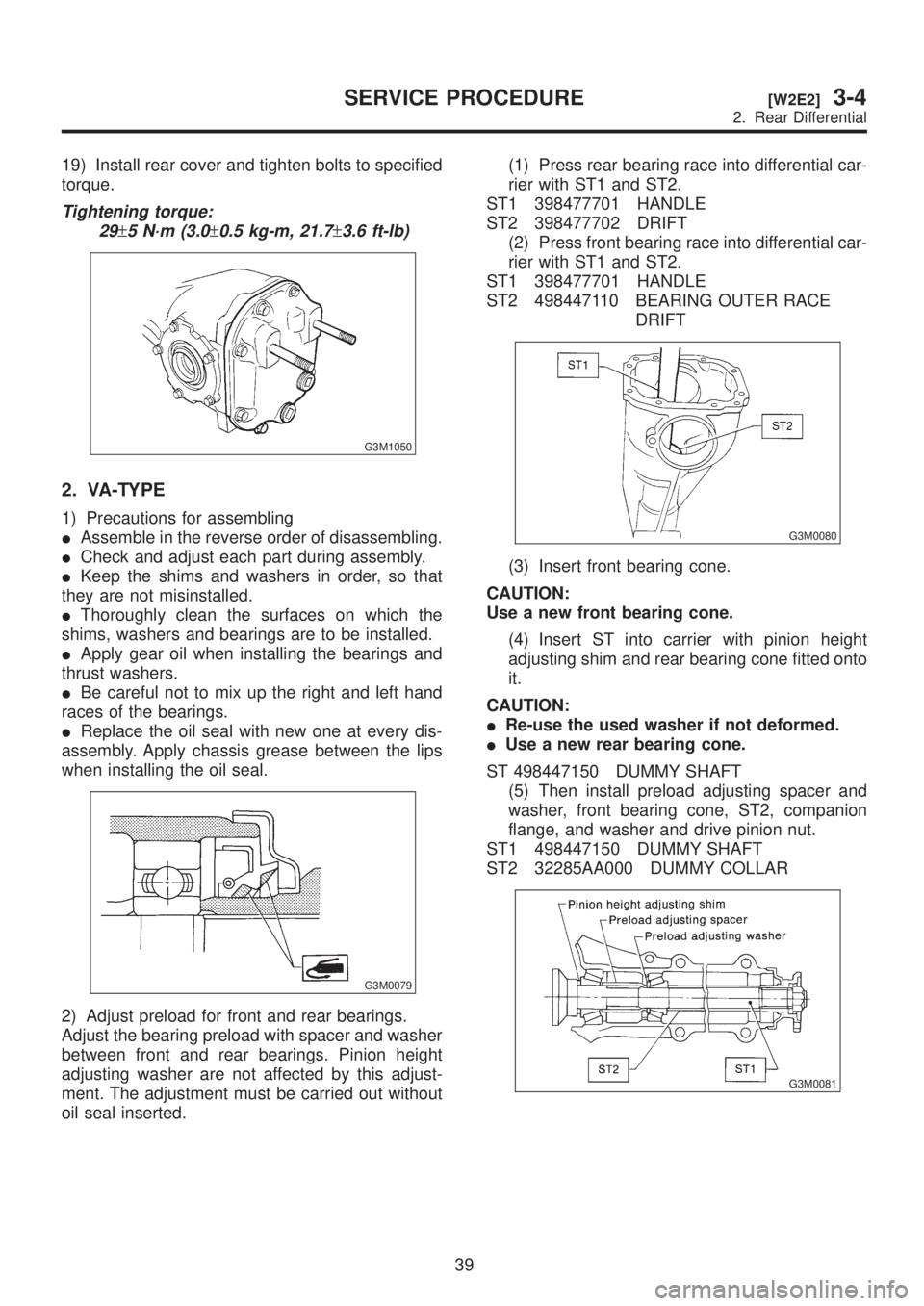
2) Adjust preload for front and rear bearings.
Adjust the bearing preload with spacer and washer
between front and rear bearings. Pinion height
adjusting washer are not affected by this adjust-
ment. The adjustment must be carried out without
oil seal inserted.(1) Press rear bearing race into differential car-
rier with ST1 and ST2.
ST1 398477701 HANDLE
ST2 398477702 DRIFT
(2) Press front bearing race into differential car-
rier with ST1 and ST2.
ST1 398477701 HANDLE
ST2 498447110 BEARING OUTER RACE
DRIFT
G3M0080
(3) Insert front bearing cone.
CAUTION:
Use a new front bearing cone.
(4) Insert ST into carrier with pinion height
adjusting shim and rear bearing cone fitted onto
it.
CAUTION:
IRe-use the used washer if not deformed.
IUse a new rear bearing cone.
ST 498447150 DUMMY SHAFT
(5) Then install preload adjusting spacer and
washer, front bearing cone, ST2, companion
flange, and washer and drive pinion nut.
ST1 498447150 DUMMY SHAFT
ST2 32285AA000 DUMMY COLLAR
G3M0081
39
[W2E2]3-4SERVICE PROCEDURE
2. Rear Differential
Page 691 of 1456

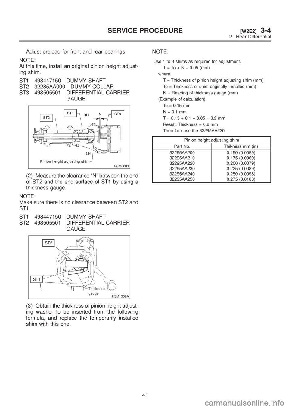
Adjust preload for front and rear bearings.
NOTE:
At this time, install an original pinion height adjust-
ing shim.
ST1 498447150 DUMMY SHAFT
ST2 32285AA000 DUMMY COLLAR
ST3 498505501 DIFFERENTIAL CARRIER
GAUGE
G3M0083
(2) Measure the clearance ªNº between the end
of ST2 and the end surface of ST1 by using a
thickness gauge.
NOTE:
Make sure there is no clearance between ST2 and
ST1.
ST1 498447150 DUMMY SHAFT
ST2 498505501 DIFFERENTIAL CARRIER
GAUGE
H3M1309A
(3) Obtain the thickness of pinion height adjust-
ing washer to be inserted from the following
formula, and replace the temporarily installed
shim with this one.NOTE:
Use 1 to 3 shims as required for adjustment.
T=To+Nþ0.05 (mm)
where
T = Thickness of pinion height adjusting shim (mm)
To = Thickness of shim originally installed (mm)
N = Reading of thickness gauge (mm)
(Example of calculation)
To = 0.15 mm
N = 0.1 mm
T = 0.15 + 0.1 þ 0.05 = 0.2 mm
Result: Thickness = 0.2 mm
Therefore use the 32295AA220.
Pinion height adjusting shim
Part No. Thikness mm (in)
32295AA200
32295AA210
32295AA220
32295AA230
32295AA240
32295AA2500.150 (0.0059)
0.175 (0.0069)
0.200 (0.0079)
0.225 (0.0089)
0.250 (0.0098)
0.275 (0.0108)
41
[W2E2]3-4SERVICE PROCEDURE
2. Rear Differential
Page 695 of 1456

(5) Measure the crown gear-to-drive pinion
backlash. Set magnet base on differential car-
rier. Align contact point of dial gauge with tooth
face of crown gear, and move crown gear while
holding drive pinion still. Read value indicated
on dial gauge.
NOTE:
If measured backlash is not within specified range,
repeat procedures for pinion crown gear set back-
lash adjustment and differential side bearing pre-
load adjustment.
Backlash:
0.10 Ð 0.15 mm (0.0039 Ð 0.0059 in)
G3M0095
15) Draw a matching mark on both differential car-
rier and holder. Remove holder one side at a time.
Replace in the original position after inserting an
O-ring and applying grease to threaded portion.
G3M0096
16) Tighten bolt of lock plate to specified torque.
Tightening torque:
25
±3 N´m (2.5±0.3 kg-m, 18.1±2.2 ft-lb)
G3M0063
17) Re-check crown gear-to-pinion backlash.
Backlash:
0.10 Ð 0.15 mm (0.0039 Ð 0.0059 in)
G3M0095
18) Check the crown gear runout on its back
surface, and make sure pinion and crown gear
rotate smoothly.
Limit of runout:
0.05 mm (0.0020 in)
G3M0097
19) Checking and adjusting tooth contact of crown
gear.
(1) Apply an even coat of red lead on both
sides of three or four teeth on the crown gear.
Check the contact pattern after rotating crown
gear several revolutions back and forth until a
definite contact pattern appears on the crown
gear.
(2) When the contact pattern is incorrect, read-
just according to the instructions given in ªTooth
contact patternº.
NOTE:
Be sure to wipe off red lead completely after
adjustment is completed.
20) If proper tooth contact is not obtained, once
again adjust the drive pinion height and the differ-
ential side bearing preload (mentioned above) and
the hypoid gear backlash.
45
[W2E2]3-4SERVICE PROCEDURE
2. Rear Differential
Page 697 of 1456

Adjusting direction of drive pinion
Adjusting direction of crown gear
TOOTH CONTACT PATTERN
Condition Contact pattern Adjustment
Correct tooth contact
Tooth contact pattern slightly shifted
towards toe under no load rotation.
(When loaded, contact pattern
moves toward heel.)
G3M0098A
Ð
Face contact
Backlash is too large.This may cause noise and chipping at
tooth ends.
G3M0098B
Increase thickness of drive pinion height
adjusting washer in order to bring drive
pinion closer to crown gear center.
G3M0098F
Flank contact
Backlash is too small.This may cause noise and stepped wear
on surfaces.
G3M0098C
Reduce thickness of drive pinion height
adjusting washer in order to move drive
pinion away from crown gear.
G3M0098G
Toe contact Contact area is small.
This may cause chipping at toe ends.
G3M0098D
Adjust as for flank contact.
G3M0098G
Heel contact Contact area is small.
This may cause chipping at heel ends.
G3M0098E
Adjust as for face contact
G3M0098F
F: INSTALLATION
To install, reverse the removal sequence.
1) Install the air breather cap tapping with a plas-
tic hammer.CAUTION:
Be sure to install new air breather cap.
2) Position front member on body by passing it
under parking brake cable and securing to rear
differential.
47
[W2F0]3-4SERVICE PROCEDURE
2. Rear Differential