Page 710 of 1456
B: INSPECTION AND ADJUSTMENT
1. WHEEL ARCH HEIGHT (FRONT AND
REAR)
1) Adjust tire pressure to specifications.
2) Set vehicle under ªcurb weightº conditions.
(Empty luggage compartment, install spare tire,jack, service tools, and top up fuel tank.)
3) Set steering wheel in a wheel-forward position.
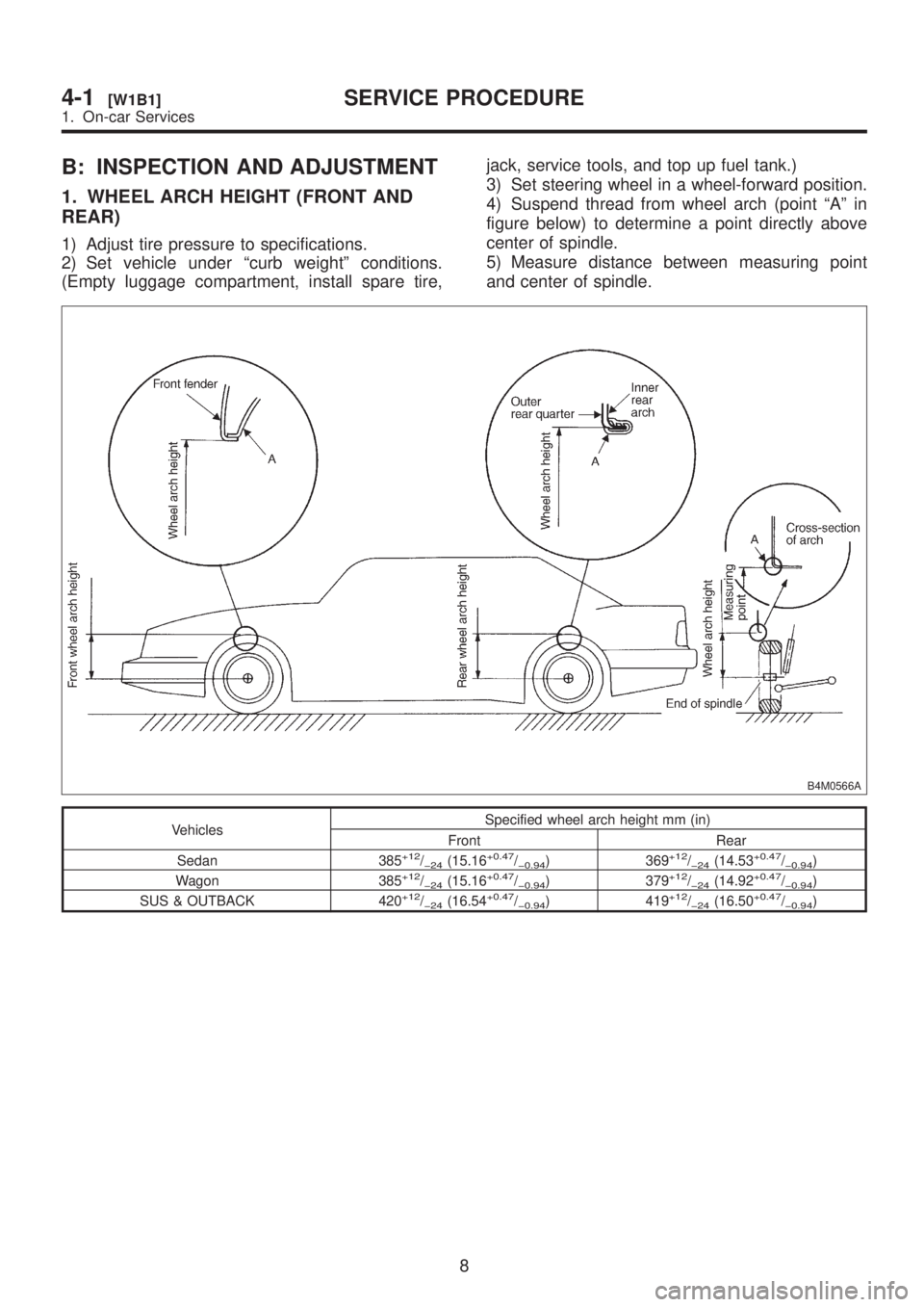
4) Suspend thread from wheel arch (point ªAº in
figure below) to determine a point directly above
center of spindle.
5) Measure distance between measuring point
and center of spindle.
B4M0566A
VehiclesSpecified wheel arch height mm (in)
Front Rear
Sedan 385
+12/þ24(15.16+0.47/þ0.94) 369+12/þ24(14.53+0.47/þ0.94)
Wagon 385+12/þ24(15.16+0.47/þ0.94) 379+12/þ24(14.92+0.47/þ0.94)
SUS & OUTBACK 420+12/þ24(16.54+0.47/þ0.94) 419+12/þ24(16.50+0.47/þ0.94)
8
4-1[W1B1]SERVICE PROCEDURE
1. On-car Services
Page 711 of 1456
2. CAMBER (FRONT AND REAR)
IInspection
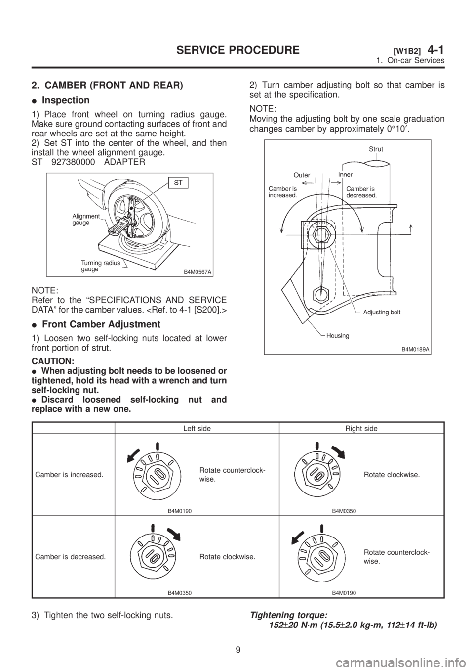
1) Place front wheel on turning radius gauge.
Make sure ground contacting surfaces of front and
rear wheels are set at the same height.
2) Set ST into the center of the wheel, and then
install the wheel alignment gauge.
ST 927380000 ADAPTER
B4M0567A
NOTE:
Refer to the ªSPECIFICATIONS AND SERVICE
DATAº for the camber values.
IFront Camber Adjustment
1) Loosen two self-locking nuts located at lower
front portion of strut.
CAUTION:
IWhen adjusting bolt needs to be loosened or
tightened, hold its head with a wrench and turn
self-locking nut.
IDiscard loosened self-locking nut and
replace with a new one.2) Turn camber adjusting bolt so that camber is
set at the specification.
NOTE:
Moving the adjusting bolt by one scale graduation
changes camber by approximately 0É10¢.
B4M0189A
Left side Right side
Camber is increased.
B4M0190
Rotate counterclock-
wise.
B4M0350
Rotate clockwise.
Camber is decreased.
B4M0350
Rotate clockwise.
B4M0190
Rotate counterclock-
wise.
3) Tighten the two self-locking nuts.Tightening torque:
152
±20 N´m (15.5±2.0 kg-m, 112±14 ft-lb)
9
[W1B2]4-1SERVICE PROCEDURE
1. On-car Services
Page 712 of 1456
3. CASTER (FRONT)
IInspection
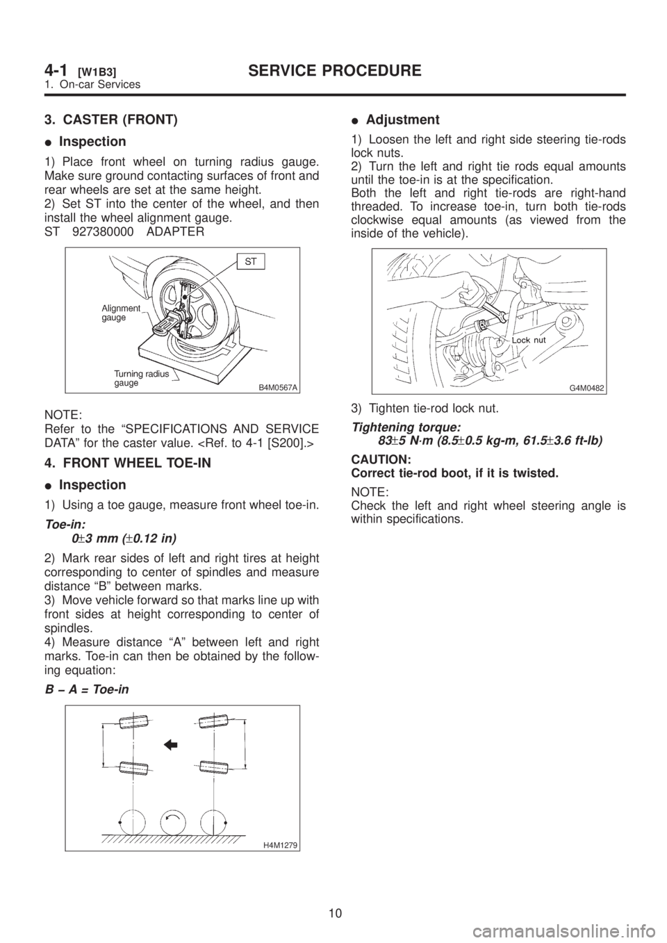
1) Place front wheel on turning radius gauge.
Make sure ground contacting surfaces of front and
rear wheels are set at the same height.
2) Set ST into the center of the wheel, and then
install the wheel alignment gauge.
ST 927380000 ADAPTER
B4M0567A
NOTE:
Refer to the ªSPECIFICATIONS AND SERVICE
DATAº for the caster value.
4. FRONT WHEEL TOE-IN
IInspection
1) Using a toe gauge, measure front wheel toe-in.
Toe-in:
0
±3mm(±0.12 in)
2) Mark rear sides of left and right tires at height
corresponding to center of spindles and measure
distance ªBº between marks.
3) Move vehicle forward so that marks line up with
front sides at height corresponding to center of
spindles.
4) Measure distance ªAº between left and right
marks. Toe-in can then be obtained by the follow-
ing equation:
B þ A = Toe-in
H4M1279
IAdjustment
1) Loosen the left and right side steering tie-rods
lock nuts.
2) Turn the left and right tie rods equal amounts
until the toe-in is at the specification.
Both the left and right tie-rods are right-hand
threaded. To increase toe-in, turn both tie-rods
clockwise equal amounts (as viewed from the
inside of the vehicle).
G4M0482
3) Tighten tie-rod lock nut.
Tightening torque:
83
±5 N´m (8.5±0.5 kg-m, 61.5±3.6 ft-lb)
CAUTION:
Correct tie-rod boot, if it is twisted.
NOTE:
Check the left and right wheel steering angle is
within specifications.
10
4-1[W1B3]SERVICE PROCEDURE
1. On-car Services
Page 713 of 1456
5. REAR WHEEL TOE-IN
IInspection
1) Using a toe-in gauge, measure rear wheel toe-
in.
Toe-in:
0
±3mm(±0.12 in)
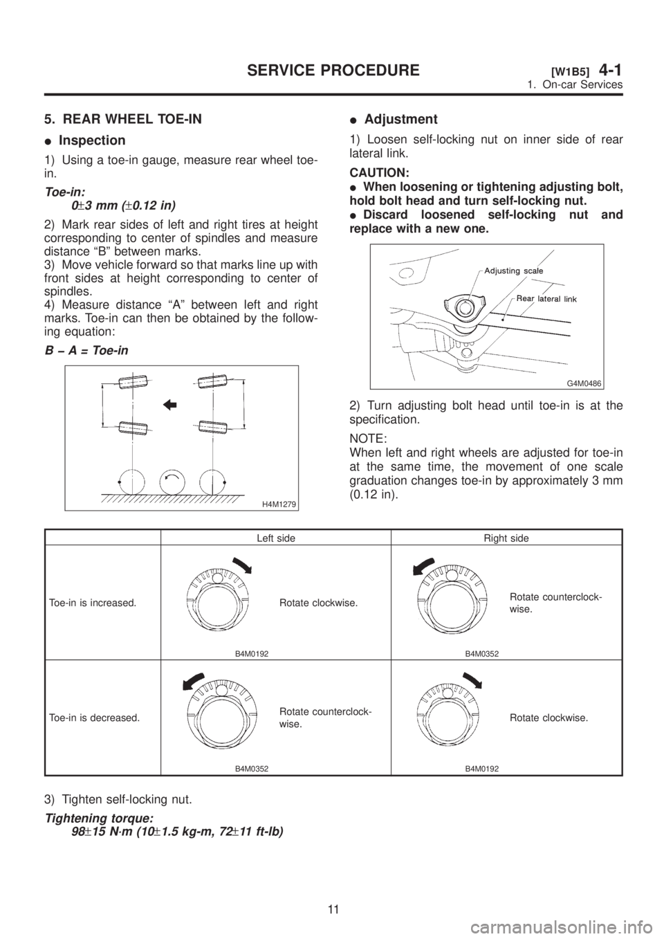
2) Mark rear sides of left and right tires at height
corresponding to center of spindles and measure
distance ªBº between marks.
3) Move vehicle forward so that marks line up with
front sides at height corresponding to center of
spindles.
4) Measure distance ªAº between left and right
marks. Toe-in can then be obtained by the follow-
ing equation:
B þ A = Toe-in
H4M1279
IAdjustment
1) Loosen self-locking nut on inner side of rear
lateral link.
CAUTION:
IWhen loosening or tightening adjusting bolt,
hold bolt head and turn self-locking nut.
IDiscard loosened self-locking nut and
replace with a new one.
G4M0486
2) Turn adjusting bolt head until toe-in is at the
specification.
NOTE:
When left and right wheels are adjusted for toe-in
at the same time, the movement of one scale
graduation changes toe-in by approximately 3 mm
(0.12 in).
Left side Right side
Toe-in is increased.
B4M0192
Rotate clockwise.
B4M0352
Rotate counterclock-
wise.
Toe-in is decreased.
B4M0352
Rotate counterclock-
wise.
B4M0192
Rotate clockwise.
3) Tighten self-locking nut.
Tightening torque:
98
±15 N´m (10±1.5 kg-m, 72±11 ft-lb)
11
[W1B5]4-1SERVICE PROCEDURE
1. On-car Services
Page 1088 of 1456

4) Tilt up assembly:
(1) Remove sunroof flame.
[W16A2].>
(2) Remove tilt up assembly.
B5M0485A
(3) Installation is in the reverse order of
removal.
B: ADJUSTMENT
1. SEDAN AND WAGON REAR (EXCEPT
OUTBACK)
1) Alignment of height between glass lid assembly
and roof panel:
(1) Remove guide rail cover.
(2) Loosen nuts and adjust height by adding
(Max: two pieces) and extracting (Max: one
piece) shim(s) (Standard: one piece) between
glass lid assembly and lid bracket.
Difference in height between glass lid assem-
bly and roof panel:
0
±0.5 mm (0±0.020 in)
B5M0314B
B5M0315B
2) Alignment of glass lid assembly with roof panel:
(1) Remove guide rail cover.
(2) Loosen nuts and move glass lid assembly
to either side to adjust front, rear, right, and left
side partitions.
Partition clearance:
7.0
±0.5 mm (0.276±0.020 in)
B5M0316A
3) Checking for movement of glass lid assembly
itself:
(1) Before installing sunroof motor, check glass
lid assembly for movement.
(2) Place a cloth on glass lid assembly and sun
shade, and attach a spring scale to glass lid
assembly edge using the cloth.
B5M0317
(3) Pull spring scale to measure force required
to move glass lid assembly.
Force required to move glass lid assembly
and sun shade trim:
Less than 196 N (20 kg, 44 lb)
Considerable effort is required to start glass lid
assembly moving, so take scale reading while
glass lid assembly is moving smoothly.
(4) If force required exceeds specifications,
check the following points:
IGlass lid assembly, sun shade and deflector and
guide rail assembly for improper installation
ICable for seizure
60
5-1[W16B1]SERVICE PROCEDURE
16. Sunroof