Page 35 of 1456

3. Engine Idle Speed
A: MEASUREMENT
1) Before checking idle speed, check the follow-
ing:
(1) Ensure that air cleaner element is free from
clogging, ignition timing is correct, spark plugs
are in good condition, and that hoses are con-
nected properly.
(2) Ensure that malfunction indicator light
(CHECK ENGINE light) does not illuminate.
2) Warm-up the engine.
3) Stop the engine, and turn ignition switch to
OFF.
4) When using SUBARU SELECT MONITOR;
NOTE:
For detailed operation procedures, refer to the
SUBARU SELECT MONITOR OPERATION
MANUAL.
(1) Insert the cartridge to SUBARU SELECT
MONITOR.
ST 24082AA090 CARTRIDGE
S2M0286A
(2) Connect SUBARU SELECT MONITOR to
the data link connector.
(3) Turn ignition switch to ON, and SUBARU
SELECT MONITOR switch to ON.
(4) Select {2. Each System Check} in Main
Menu.
(5) Select {EGI/EMPI} in Selection Menu.
(6) Select {1. Current Data Display & Save} in
EGI/EMPI Diagnosis.
(7) Select {1.12 Data Display} in Data Display
Menu.(8) Start the engine, and read engine idle
speed.
S2M0098
5) When using tachometer (Secondary pick-up
type).
(1) Attach the pick-up clip to No. 1 cylinder
spark plug cord.
(2) Start the engine, and read engine idle
speed.
B2M2011
NOTE:
IWhen using the OBD-II general scan tool, care-
fully read its operation manual.
IThis ignition system provides simultaneous igni-
tion for #1 and #2 plugs. It must be noted that
some tachometers may register twice that of actual
engine speed.
6) Check idle speed when unloaded. (With
headlights, heater fan, rear defroster, radiator fan,
air conditioning, etc. OFF)
Idle speed (No load and gears in neutral (MT),
or N or P (AT) position):
700
±100 rpm
7) Check idle speed when loaded. (Turn air con-
ditioning switch to |P¢rdquo;ON|P'ldquo; and oper-
ate compressor for at least one minute before
measurement.)
Idle speed [A/C ªONº, no load and gears in
neutral (MT) or N or P (AT) position]:
850
±50 rpm
3
[W3A0]2-2SERVICE PROCEDURE
3. Engine Idle Speed
Page 132 of 1456

2. Engine Noise
Type of sound Condition Possible cause
Regular clicking soundSound increases as engine
speed increases.IValve mechanism is defective.
IIncorrect valve clearance
IWorn valve rocker
IWorn camshaft
IBroken valve spring
Heavy and dull clankOil pressure is low.IWorn crankshaft main bearing
IWorn connecting rod bearing (big end)
Oil pressure is normal.ILoose flywheel mounting bolts
IDamaged engine mounting
High-pitched clank
(Spark knock)Sound is noticeable when
accelerating with an overload.IIgnition timing advanced
IAccumulation of carbon inside combustion chamber
IWrong spark plug
IImproper gasoline
Clank when engine speed is
medium (1,000 to 2,000 rpm)Sound is reduced when fuel
injector connector of noisy cyl-
inder is disconnected.
(NOTE*)IWorn crankshaft main bearing
IWorn bearing at crankshaft end of connecting rod
Knocking sound when engine
is operating under idling speed
and engine is warmSound is reduced when fuel
injector connector of noisy cyl-
inder is disconnected.
(NOTE*)IWorn cylinder liner and piston ring
IBroken or stuck piston ring
IWorn piston pin and hole at piston end of connecting rod
Sound is not reduced if each
fuel injector connector is dis-
connected in turn. (NOTE*)IUnusually worn valve lifter
IWorn cam gear
IWorn camshaft journal bore in crankcase
Squeaky sound ÐIInsufficient generator lubrication
Rubbing sound ÐIDefective generator brush and rotor contact
Gear scream when starting
engineÐIDefective ignition starter switch
IWorn gear and starter pinion
Sound like polishing glass with
a dry clothÐILoose drive belt
IDefective engine coolant pump shaft
Hissing sound ÐILoss of compression
IAir leakage in air intake system, hoses, connections or
manifolds
Timing belt noise ÐILoose timing belt
IBelt contacting case/adjacent part
Valve tappet noise ÐIIncorrect valve clearance
NOTE*:
When disconnecting fuel injector connector, Malfunction Indicator Light (CHECK ENGINE light) illuminates and trouble code is
stored in ECM memory.
Therefore, carry out the CLEAR MEMORY MODE and INSPECTION MODE after con-
necting fuel injector connector.
78
2-3a[K200]DIAGNOSTICS
2. Engine Noise
Page 145 of 1456
2. Timing Belt
A: REMOVAL
1. CRANKSHAFT PULLEY AND BELT COVER
B2M1705C
(1) V-belt
(2) Crankshaft pulley bolt(3) Crankshaft pulley
(4) Left-hand belt cover No. 1(5) Right-hand belt cover No. 1
(6) Front belt cover
1) Remove V-belt cover, V-belt and air condition-
ing compressor drive belt tensioner.
[G2B0].>
B2M1706
2) Remove pulley bolt. To lock crankshaft, use ST.
ST 499977100 CRANKSHAFT PULLEY
WRENCH
H2M2393A
3) Remove crankshaft pulley.
4) Remove left-hand belt cover.
B2M0729
14
2-3b[W2A1]SERVICE PROCEDURE
2. Timing Belt
Page 160 of 1456
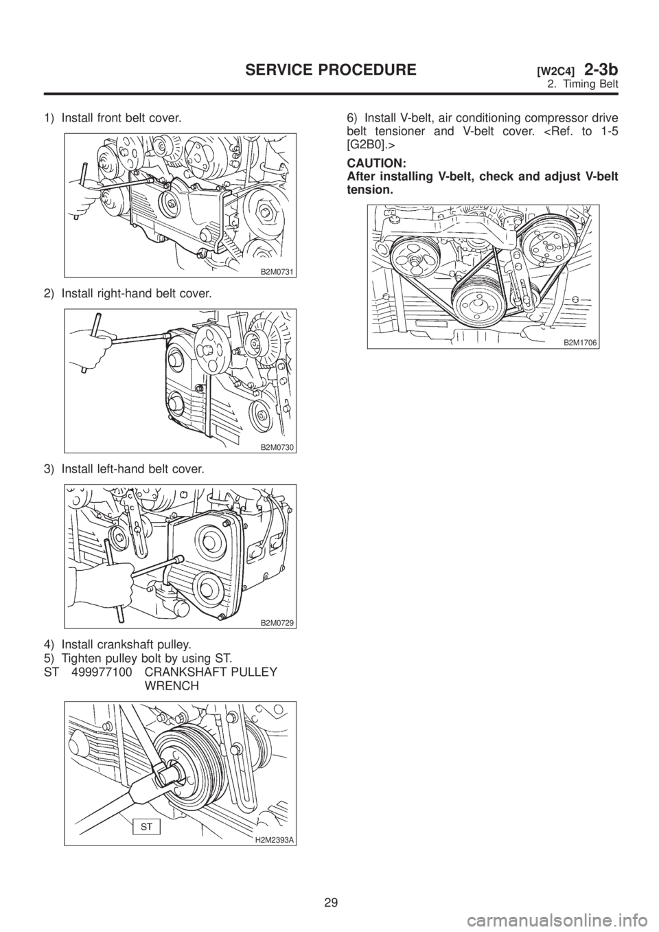
1) Install front belt cover.
B2M0731
2) Install right-hand belt cover.
B2M0730
3) Install left-hand belt cover.
B2M0729
4) Install crankshaft pulley.
5) Tighten pulley bolt by using ST.
ST 499977100 CRANKSHAFT PULLEY
WRENCH
H2M2393A
6) Install V-belt, air conditioning compressor drive
belt tensioner and V-belt cover.
[G2B0].>
CAUTION:
After installing V-belt, check and adjust V-belt
tension.
B2M1706
29
[W2C4]2-3bSERVICE PROCEDURE
2. Timing Belt
Page 167 of 1456
4. Cylinder Head
A: REMOVAL
1. RELATED PARTS
1) Remove V-belt.
2) Remove generator, air conditioner compressor
and brackets.
3) Remove hoses and tubes from cylinder block.
4) Disconnect each connector and/or remove con-
nector bracket.5) Remove intake manifold assembly and gasket.
6) Remove camshaft position sensor.
7) Remove timing belt, camshaft sprockets and
related parts.
8) Remove rocker cover, camshafts and related
parts.
2. CYLINDER HEAD
S2M0421A
(1) Bolt
(2) Cylinder head bolt(3) Cylinder head
(4) Cylinder head gasket
1) Remove oil level gauge guide attaching bolt
(LH side only).
36
2-3b[W4A1]SERVICE PROCEDURE
4. Cylinder Head
Page 178 of 1456
3) Install camshaft sprockets, timing belt and related parts.
S2M0303
4) Install intake manifold.
CAUTION:
Use new gaskets.
G2M0774
5) Install camshaft position sensor. Use dry com-
pressed air to remove foreign particles before
installing sensor.
6) Connect each connector and/or install connec-
tor bracket.
7) Connect hoses and tubes to cylinder block.
8) Install brackets, generator and air conditioner
compressor.
9) Install V-belt.
47
[W4E2]2-3bSERVICE PROCEDURE
4. Cylinder Head
Page 207 of 1456
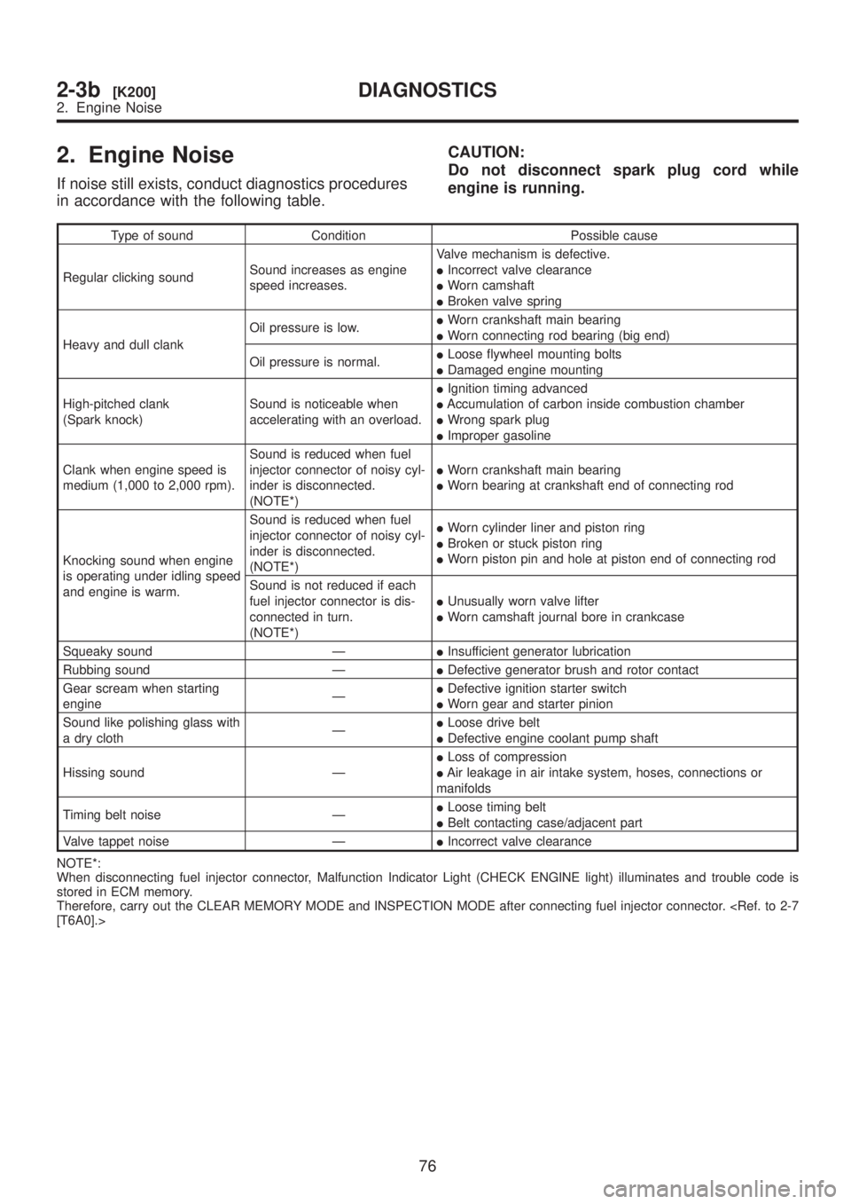
2. Engine Noise
If noise still exists, conduct diagnostics procedures
in accordance with the following table.CAUTION:
Do not disconnect spark plug cord while
engine is running.
Type of sound Condition Possible cause
Regular clicking soundSound increases as engine
speed increases.Valve mechanism is defective.
IIncorrect valve clearance
IWorn camshaft
IBroken valve spring
Heavy and dull clankOil pressure is low.IWorn crankshaft main bearing
IWorn connecting rod bearing (big end)
Oil pressure is normal.ILoose flywheel mounting bolts
IDamaged engine mounting
High-pitched clank
(Spark knock)Sound is noticeable when
accelerating with an overload.IIgnition timing advanced
IAccumulation of carbon inside combustion chamber
IWrong spark plug
IImproper gasoline
Clank when engine speed is
medium (1,000 to 2,000 rpm).Sound is reduced when fuel
injector connector of noisy cyl-
inder is disconnected.
(NOTE*)IWorn crankshaft main bearing
IWorn bearing at crankshaft end of connecting rod
Knocking sound when engine
is operating under idling speed
and engine is warm.Sound is reduced when fuel
injector connector of noisy cyl-
inder is disconnected.
(NOTE*)IWorn cylinder liner and piston ring
IBroken or stuck piston ring
IWorn piston pin and hole at piston end of connecting rod
Sound is not reduced if each
fuel injector connector is dis-
connected in turn.
(NOTE*)IUnusually worn valve lifter
IWorn camshaft journal bore in crankcase
Squeaky sound ÐIInsufficient generator lubrication
Rubbing sound ÐIDefective generator brush and rotor contact
Gear scream when starting
engineÐIDefective ignition starter switch
IWorn gear and starter pinion
Sound like polishing glass with
a dry clothÐILoose drive belt
IDefective engine coolant pump shaft
Hissing sound ÐILoss of compression
IAir leakage in air intake system, hoses, connections or
manifolds
Timing belt noise ÐILoose timing belt
IBelt contacting case/adjacent part
Valve tappet noise ÐIIncorrect valve clearance
NOTE*:
When disconnecting fuel injector connector, Malfunction Indicator Light (CHECK ENGINE light) illuminates and trouble code is
stored in ECM memory.
Therefore, carry out the CLEAR MEMORY MODE and INSPECTION MODE after connecting fuel injector connector.
[T6A0].>
76
2-3b[K200]DIAGNOSTICS
2. Engine Noise
Page 342 of 1456

3) Disconnect air by-pass hose from air intake
duct.
S2M0102A
4) Slowly pour one can (16 oz) of cleaner into by-
pass air hole.
Cleaner:
Part No. 1050002 GM Top Engine Cleaner
Part No. X66-A AC Delco Carburetor
Tune-up Conditioner
S2M0103
5) Leave the engine running for five minutes.
NOTE:
Let white smoke come out from muffler until the
cleaner is used up.
6) Stop the engine.
7) Release the throttle valve.
8) Connect air by-pass hose to air intake duct.
S2M0102A
9) Check duty ratio of idle air control solenoid
valve using Subaru Select Monitor.
NOTE:
For detailed operation procedures, refer to the
Subaru Select Monitor Operation Manual.(1) Insert the cartridge to Subaru Select Moni-
tor.
ST 24082AA090 CARTRIDGE
S2M0286A
(2) Connect Subaru Select Monitor to the data
link connector.
(3) Turn ignition switch to ON, and Subaru
Select Monitor switch to ON.
(4) Select {2. Each System Check} in Main
Menu.
(5) Select {EGI/EMPI} in Selection Menu.
(6) Select {1. Current Data Display & Save} in
EGI/EMPI Diagnosis.
(7) Select {1.12 Data Display} in Data Display
Menu.
(8) Adjust throttle position sensor to the proper
position to match with the following specifica-
tion.
ISC valve duty ratio: 25 Ð 40%
S2M0098
78
2-7[W12B0]SERVICE PROCEDURE
12. Idle Air Control Solenoid Valve


![SUBARU LEGACY 1999 Service Repair Manual 3) Install camshaft sprockets, timing belt and related parts.
<Ref. to 2-3b [W2C1].>
S2M0303
4) Install intake manifold.
CAUTION:
Use new gaskets.
G2M0774
5) Install camshaft position sensor. Use dry](/manual-img/17/57435/w960_57435-177.png "SUBARU LEGACY 1999 Service Repair Manual 3) Install camshaft sprockets, timing belt and related parts.
<Ref. to 2-3b [W2C1].>
S2M0303
4) Install intake manifold.
CAUTION:
Use new gaskets.
G2M0774
5) Install camshaft position sensor. Use dry")