Page 1284 of 1456

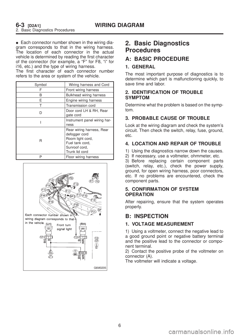
IEach connector number shown in the wiring dia-
gram corresponds to that in the wiring harness.
The location of each connector in the actual
vehicle is determined by reading the first character
of the connector (for example, a ªFº for F8, ªiº for
i16, etc.) and the type of wiring harness.
The first character of each connector number
refers to the area or system of the vehicle.
Symbol Wiring harness and Cord
F Front wiring harness
B Bulkhead wiring harness
E Engine wiring harness
T Transmission cord
DDoor cord LH & RH, Rear
gate cord
IInstrument panel wiring har-
ness
RRear wiring harness, Rear
defogger cord
Room light cord,
Fuel tank cord,
Sunroof cord,
Trunk lid cord
P Floor wiring harness
G6M0205
2. Basic Diagnostics
Procedures
A: BASIC PROCEDURE
1. GENERAL
The most important purpose of diagnostics is to
determine which part is malfunctioning quickly, to
save time and labor.
2. IDENTIFICATION OF TROUBLE
SYMPTOM
Determine what the problem is based on the symp-
tom.
3. PROBABLE CAUSE OF TROUBLE
Look at the wiring diagram and check the system's
circuit. Then check the switch, relay, fuse, ground,
etc.
4. LOCATION AND REPAIR OF TROUBLE
1) Using the diagnostics narrow down the causes.
2) If necessary, use a voltmeter, ohmmeter, etc.
3) Before replacing certain component parts
(switch, relay, etc.), check the power supply,
ground, for open wiring harness, poor connectors,
etc. If no problems are encountered, check the
component parts.
5. CONFIRMATION OF SYSTEM
OPERATION
After repairing, ensure that the system operates
properly.
B: INSPECTION
1. VOLTAGE MEASUREMENT
1) Using a voltmeter, connect the negative lead to
a good ground point or negative battery terminal
and the positive lead to the connector or compo-
nent terminal.
2) Contact the positive probe of the voltmeter on
connector (A).
The voltmeter will indicate a voltage.
6
6-3[D2A1]WIRING DIAGRAM
2. Basic Diagnostics Procedures
Page 1285 of 1456

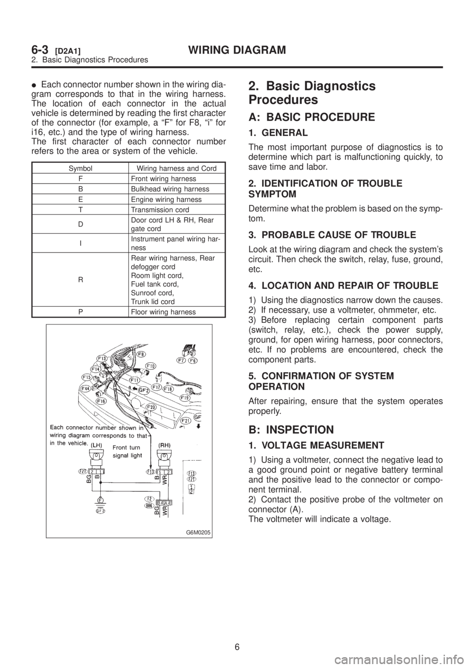
IEach connector number shown in the wiring dia-
gram corresponds to that in the wiring harness.
The location of each connector in the actual
vehicle is determined by reading the first character
of the connector (for example, a ªFº for F8, ªiº for
i16, etc.) and the type of wiring harness.
The first character of each connector number
refers to the area or system of the vehicle.
Symbol Wiring harness and Cord
F Front wiring harness
B Bulkhead wiring harness
E Engine wiring harness
T Transmission cord
DDoor cord LH & RH, Rear
gate cord
IInstrument panel wiring har-
ness
RRear wiring harness, Rear
defogger cord
Room light cord,
Fuel tank cord,
Sunroof cord,
Trunk lid cord
P Floor wiring harness
G6M0205
2. Basic Diagnostics
Procedures
A: BASIC PROCEDURE
1. GENERAL
The most important purpose of diagnostics is to
determine which part is malfunctioning quickly, to
save time and labor.
2. IDENTIFICATION OF TROUBLE
SYMPTOM
Determine what the problem is based on the symp-
tom.
3. PROBABLE CAUSE OF TROUBLE
Look at the wiring diagram and check the system's
circuit. Then check the switch, relay, fuse, ground,
etc.
4. LOCATION AND REPAIR OF TROUBLE
1) Using the diagnostics narrow down the causes.
2) If necessary, use a voltmeter, ohmmeter, etc.
3) Before replacing certain component parts
(switch, relay, etc.), check the power supply,
ground, for open wiring harness, poor connectors,
etc. If no problems are encountered, check the
component parts.
5. CONFIRMATION OF SYSTEM
OPERATION
After repairing, ensure that the system operates
properly.
B: INSPECTION
1. VOLTAGE MEASUREMENT
1) Using a voltmeter, connect the negative lead to
a good ground point or negative battery terminal
and the positive lead to the connector or compo-
nent terminal.
2) Contact the positive probe of the voltmeter on
connector (A).
The voltmeter will indicate a voltage.
6
6-3[D2A1]WIRING DIAGRAM
2. Basic Diagnostics Procedures
Page 1352 of 1456
N: FUEL GAUGE SYSTEM
1. TAIWAN MODEL
72
6-3[D6N1]WIRING DIAGRAM
6. Wiring Diagram
Page 1450 of 1456

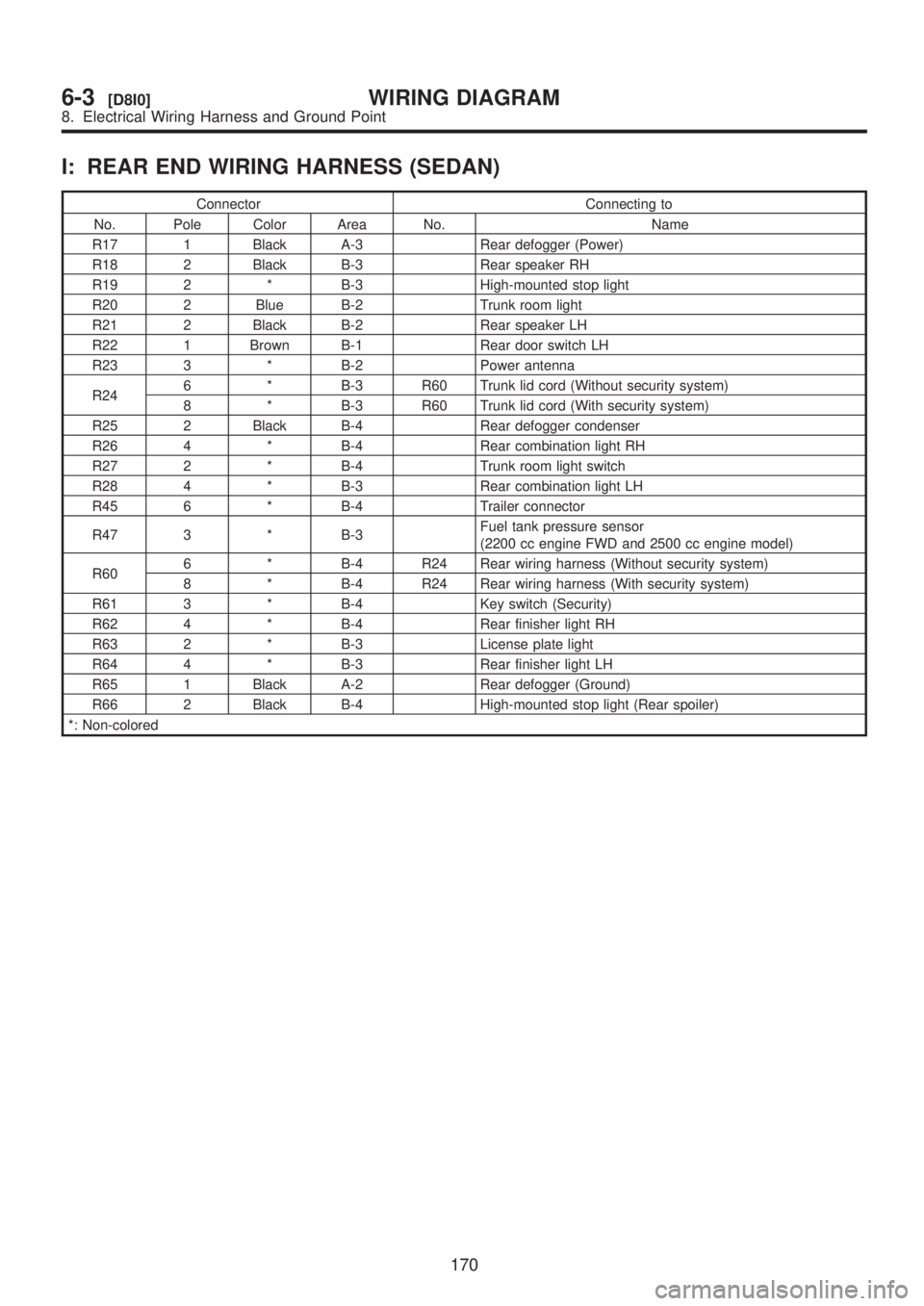
I: REAR END WIRING HARNESS (SEDAN)
Connector Connecting to
No. Pole Color Area No. Name
R17 1 Black A-3 Rear defogger (Power)
R18 2 Black B-3 Rear speaker RH
R19 2 * B-3 High-mounted stop light
R20 2 Blue B-2 Trunk room light
R21 2 Black B-2 Rear speaker LH
R22 1 Brown B-1 Rear door switch LH
R23 3 * B-2 Power antenna
R246 * B-3 R60 Trunk lid cord (Without security system)
8 * B-3 R60 Trunk lid cord (With security system)
R25 2 Black B-4 Rear defogger condenser
R26 4 * B-4 Rear combination light RH
R27 2 * B-4 Trunk room light switch
R28 4 * B-3 Rear combination light LH
R45 6 * B-4 Trailer connector
R47 3 * B-3Fuel tank pressure sensor
(2200 cc engine FWD and 2500 cc engine model)
R606 * B-4 R24 Rear wiring harness (Without security system)
8 * B-4 R24 Rear wiring harness (With security system)
R61 3 * B-4 Key switch (Security)
R62 4 * B-4 Rear finisher light RH
R63 2 * B-3 License plate light
R64 4 * B-3 Rear finisher light LH
R65 1 Black A-2 Rear defogger (Ground)
R66 2 Black B-4 High-mounted stop light (Rear spoiler)
*: Non-colored
170
6-3[D8I0]WIRING DIAGRAM
8. Electrical Wiring Harness and Ground Point
Page 1452 of 1456

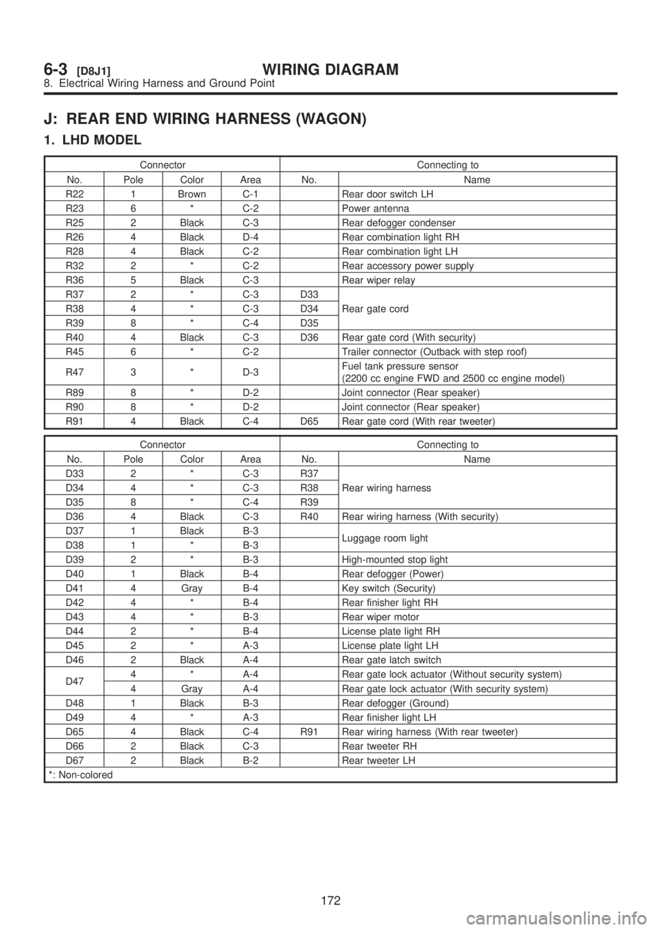
J: REAR END WIRING HARNESS (WAGON)
1. LHD MODEL
Connector Connecting to
No. Pole Color Area No. Name
R22 1 Brown C-1 Rear door switch LH
R23 6 * C-2 Power antenna
R25 2 Black C-3 Rear defogger condenser
R26 4 Black D-4 Rear combination light RH
R28 4 Black C-2 Rear combination light LH
R32 2 * C-2 Rear accessory power supply
R36 5 Black C-3 Rear wiper relay
R37 2 * C-3 D33
Rear gate cord R38 4 * C-3 D34
R39 8 * C-4 D35
R40 4 Black C-3 D36 Rear gate cord (With security)
R45 6 * C-2 Trailer connector (Outback with step roof)
R47 3 * D-3Fuel tank pressure sensor
(2200 cc engine FWD and 2500 cc engine model)
R89 8 * D-2 Joint connector (Rear speaker)
R90 8 * D-2 Joint connector (Rear speaker)
R91 4 Black C-4 D65 Rear gate cord (With rear tweeter)
Connector Connecting to
No. Pole Color Area No. Name
D33 2 * C-3 R37
Rear wiring harness D34 4 * C-3 R38
D35 8 * C-4 R39
D36 4 Black C-3 R40 Rear wiring harness (With security)
D37 1 Black B-3
Luggage room light
D38 1 * B-3
D39 2 * B-3 High-mounted stop light
D40 1 Black B-4 Rear defogger (Power)
D41 4 Gray B-4 Key switch (Security)
D42 4 * B-4 Rear finisher light RH
D43 4 * B-3 Rear wiper motor
D44 2 * B-4 License plate light RH
D45 2 * A-3 License plate light LH
D46 2 Black A-4 Rear gate latch switch
D474 * A-4 Rear gate lock actuator (Without security system)
4 Gray A-4 Rear gate lock actuator (With security system)
D48 1 Black B-3 Rear defogger (Ground)
D49 4 * A-3 Rear finisher light LH
D65 4 Black C-4 R91 Rear wiring harness (With rear tweeter)
D66 2 Black C-3 Rear tweeter RH
D67 2 Black B-2 Rear tweeter LH
*: Non-colored
172
6-3[D8J1]WIRING DIAGRAM
8. Electrical Wiring Harness and Ground Point