Page 227 of 1456

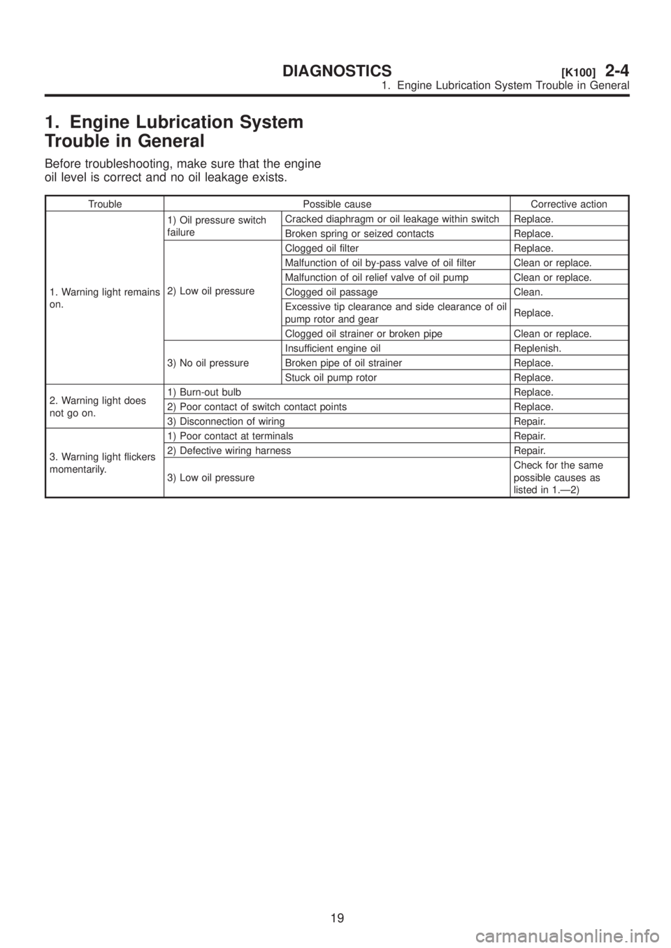
1. Engine Lubrication System
Trouble in General
Before troubleshooting, make sure that the engine
oil level is correct and no oil leakage exists.
Trouble Possible cause Corrective action
1. Warning light remains
on.1) Oil pressure switch
failureCracked diaphragm or oil leakage within switch Replace.
Broken spring or seized contacts Replace.
2) Low oil pressureClogged oil filter Replace.
Malfunction of oil by-pass valve of oil filter Clean or replace.
Malfunction of oil relief valve of oil pump Clean or replace.
Clogged oil passage Clean.
Excessive tip clearance and side clearance of oil
pump rotor and gearReplace.
Clogged oil strainer or broken pipe Clean or replace.
3) No oil pressureInsufficient engine oil Replenish.
Broken pipe of oil strainer Replace.
Stuck oil pump rotor Replace.
2. Warning light does
not go on.1) Burn-out bulb Replace.
2) Poor contact of switch contact points Replace.
3) Disconnection of wiring Repair.
3. Warning light flickers
momentarily.1) Poor contact at terminals Repair.
2) Defective wiring harness Repair.
3) Low oil pressureCheck for the same
possible causes as
listed in 1.Ð2)
19
[K100]2-4DIAGNOSTICS
1. Engine Lubrication System Trouble in General
Page 561 of 1456

5) Remove control valve body.
CAUTION:
When removing control valve body, be careful
not to interfere with transfer duty solenoid C
wiring.
NOTE:
Be careful because oil flows from valve body.
B3M1037
6) Remove oil strainer.
NOTE:
Be careful because oil flows from oil strainer.
B3M1038A
7) Remove solenoids and duty solenoids.
B3M1039A
(A) Lock-up duty solenoid (Blue)
(B) Low clutch timing solenoid (Gray)
(C) Line pressure duty solenoid (Red)
(D) Shift solenoid 2 (Yellow)
(E) Shift solenoid 1 (Green)
(F) 2-4 brake timing solenoid (Black)
(G) 2-4 brake duty solenoid (Red)
(H) ATF temperature sensor
B: INSTALLATION
1) Install 7 solenoids and ATF temperature sensor.
Tightening torque:
T: 8
±1 N´m (0.8±0.1 kg-m, 5.8±0.7 ft-lb)
B3M1039B
(A) Lock-up duty solenoid (Blue)
(B) Low clutch timing solenoid (Gray)
(C) Line pressure duty solenoid (Red)
(D) Shift solenoid 2 (Yellow)
(E) Shift solenoid 1 (Green)
(F) 2-4 brake timing solenoid (Black)
(G) 2-4 brake duty solenoid (Red)
(H) ATF temperature sensor
2) Install oil strainer.
Tightening torque:
8
±1 N´m (0.8±0.1 kg-m, 5.8±0.7 ft-lb)
B3M1038B
(A) Short bolt
(B) Middle bolt
(C) Long bolt
35
[W4B0]3-2SERVICE PROCEDURE
4. Shift Solenoid, Duty Solenoid and Valve
Page 579 of 1456
6) Remove the oil pan.
NOTE:
Use a scraper to remove oil pan.
B3M1065A
7) Disconnect the harness connectors for the
solenoids, duty solenoids, ATF temperature sensor
and the ground cord.
B2M2263C
(A) Lock-up duty solenoid (Blue)
(B) Low clutch timing solenoid (Gray)
(C) Line pressure duty solenoid (Red)
(D) Shift solenoid 2 (Yellow)
(E) Shift solenoid 1 (Green)
(F) 2-4 brake timing solenoid (Black)
(G) 2-4 brake duty solenoid (Red)
(H) ATF temperature sensor
8) Remove the control valve body.
CAUTION:
When removing control valve body, be careful
not to interfere with transfer duty solenoid C
wiring.
B3M1037A
9) Remove vehicle speed sensor 2 (front) and
torque converter turbine speed sensor.
B3M1066A
10) Remove transmission harness.
B3M1067A
11) Remove the oil pump housing.
CAUTION:
Be careful not to lose the total end play adjust-
ing thrust washer.
B3M1068A
12) Remove 2-4 brake seal.
B3M1069A
50
3-2[W11B3]SERVICE PROCEDURE
11. Overall Transmission
Page 801 of 1456
1. Supplemental Restraint
System ªAirbagº
A: PRECAUTION
Airbag system wiring harness is routed near the
steering wheel, steering shaft and column.
WARNING:
IAll Airbag system wiring harness and con-
nectors are colored yellow. Do not use electri-cal test equipment on these circuit.
IBe careful not to damage Airbag system wir-
ing harness when servicing the steering wheel,
steering shaft and column.
10
4-3[W1A0]SERVICE PROCEDURE
1. Supplemental Restraint System ªAirbagº
Page 803 of 1456

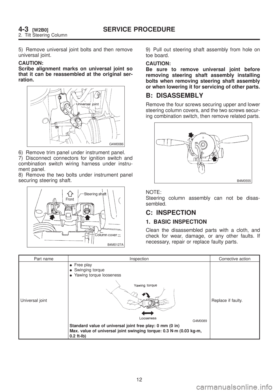
5) Remove universal joint bolts and then remove
universal joint.
CAUTION:
Scribe alignment marks on universal joint so
that it can be reassembled at the original ser-
ration.
G4M0086
6) Remove trim panel under instrument panel.
7) Disconnect connectors for ignition switch and
combination switch wiring harness under instru-
ment panel.
8) Remove the two bolts under instrument panel
securing steering shaft.
B4M0127A
9) Pull out steering shaft assembly from hole on
toe board.
CAUTION:
Be sure to remove universal joint before
removing steering shaft assembly installing
bolts when removing steering shaft assembly
or when lowering it for servicing of other parts.
B: DISASSEMBLY
Remove the four screws securing upper and lower
steering column covers, and the two screws secur-
ing combination switch, then remove related parts.
B4M0555
NOTE:
Steering column assembly can not be disas-
sembled.
C: INSPECTION
1. BASIC INSPECTION
Clean the disassembled parts with a cloth, and
check for wear, damage, or any other faults. If
necessary, repair or replace faulty parts.
Part name Inspection Corrective action
Universal jointIFree play
ISwinging torque
IYawing torque looseness
G4M0089
Standard value of universal joint free play: 0 mm (0 in)
Max. value of universal joint swinging torque: 0.3 N´m (0.03 kg-m,
0.2 ft-lb)Replace if faulty.
12
4-3[W2B0]SERVICE PROCEDURE
2. Tilt Steering Column
Page 941 of 1456

4) Install front ABS sensor on strut and wheel
apron bracket.
Tightening torque:
32
±10 N´m (3.3±1.0 kg-m, 24±7 ft-lb)
B4M1442A
5) Place a thickness gauge between ABS sensor's
pole piece and tone wheel's tooth face. After stan-
dard clearance is obtained over the entire
perimeter, tighten ABS sensor on housing to speci-
fied torque.
ABS sensor standard clearance:
0.9 Ð 1.4 mm (0.035 Ð 0.055 in)
Tightening torque:
32
±10 N´m (3.3±1.0 kg-m, 24±7 ft-lb)
CAUTION:
Check the marks on the harness to make sure
that no distortion exists. (RH: white, LH: yel-
low)
NOTE:
If the clearance is outside specifications, readjust.
17. Brake Pipe
A: SUPPLEMENTAL RESTRAINT
SYSTEM ªAIRBAGº
Airbag system wiring harness is routed near the
center brake pipe.
CAUTION:
IAll Airbag system wiring harness and con-
nectors are colored yellow. Do not use electri-
cal test equipment on these circuit.
IBe careful not to damage Airbag system wir-
ing harness when servicing the center brake
pipe.
B: REMOVAL AND INSTALLATION
CAUTION:
IWhen removing and installing the brake
pipe, make sure that it is not bent.
IAfter installing the brake pipe and hose,
bleed the air.
IAfter installing the brake hose, make sure
that it does not touch the tire or suspension
assembly, etc.
Brake pipe tightening torque:
15+3/þ2N´m (1.5+0.3/þ0.2kg-m, 10.8+2.2/þ1.4ft-lb)
63
[W17B0]4-4SERVICE PROCEDURE
17. Brake Pipe
Page 942 of 1456

4) Install front ABS sensor on strut and wheel
apron bracket.
Tightening torque:
32
±10 N´m (3.3±1.0 kg-m, 24±7 ft-lb)
B4M1442A
5) Place a thickness gauge between ABS sensor's
pole piece and tone wheel's tooth face. After stan-
dard clearance is obtained over the entire
perimeter, tighten ABS sensor on housing to speci-
fied torque.
ABS sensor standard clearance:
0.9 Ð 1.4 mm (0.035 Ð 0.055 in)
Tightening torque:
32
±10 N´m (3.3±1.0 kg-m, 24±7 ft-lb)
CAUTION:
Check the marks on the harness to make sure
that no distortion exists. (RH: white, LH: yel-
low)
NOTE:
If the clearance is outside specifications, readjust.
17. Brake Pipe
A: SUPPLEMENTAL RESTRAINT
SYSTEM ªAIRBAGº
Airbag system wiring harness is routed near the
center brake pipe.
CAUTION:
IAll Airbag system wiring harness and con-
nectors are colored yellow. Do not use electri-
cal test equipment on these circuit.
IBe careful not to damage Airbag system wir-
ing harness when servicing the center brake
pipe.
B: REMOVAL AND INSTALLATION
CAUTION:
IWhen removing and installing the brake
pipe, make sure that it is not bent.
IAfter installing the brake pipe and hose,
bleed the air.
IAfter installing the brake hose, make sure
that it does not touch the tire or suspension
assembly, etc.
Brake pipe tightening torque:
15+3/þ2N´m (1.5+0.3/þ0.2kg-m, 10.8+2.2/þ1.4ft-lb)
63
[W17B0]4-4SERVICE PROCEDURE
17. Brake Pipe
Page 967 of 1456

1. Precaution
A: SUPPLEMENTAL RESTRAINT
SYSTEM ªAIRBAGº
CAUTION:
IAll Airbag system wiring harness and con-
nectors are colored yellow. Do not use electri-
cal test equipment on these circuit.
IBe careful not to damage Airbag system wir-
ing harness when servicing the instrument
panel, heater unit, blower motor and control
unit.
Airbag system wiring harness is routed near the
instrument panel, heater unit, blower motor and
control unit.
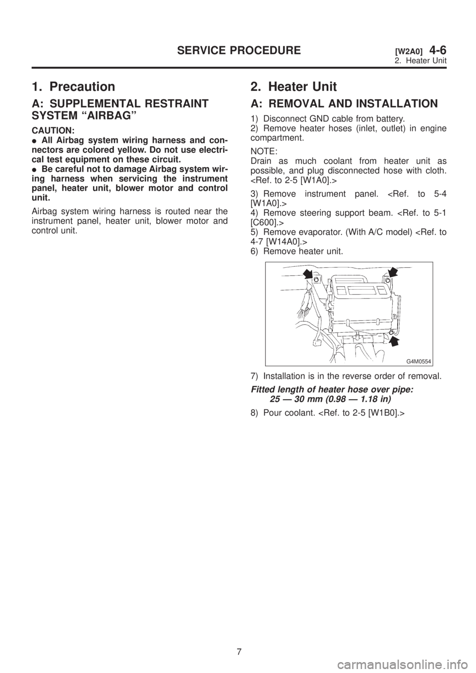
2. Heater Unit
A: REMOVAL AND INSTALLATION
1) Disconnect GND cable from battery.
2) Remove heater hoses (inlet, outlet) in engine
compartment.
NOTE:
Drain as much coolant from heater unit as
possible, and plug disconnected hose with cloth.
3) Remove instrument panel.
[W1A0].>
4) Remove steering support beam.
[C600].>
5) Remove evaporator. (With A/C model)
4-7 [W14A0].>
6) Remove heater unit.
G4M0554
7) Installation is in the reverse order of removal.
Fitted length of heater hose over pipe:
25 Ð 30 mm (0.98 Ð 1.18 in)
8) Pour coolant.
7
[W2A0]4-6SERVICE PROCEDURE
2. Heater Unit