Page 348 of 1456
9) Remove spark plug cords from spark plugs (#1
and #3 cylinders).
B2M2024
10) Remove fuel pipe protector LH. (LHD model
only)
B2M2754
11) Remove band which holds engine harness to
fuel injector pipe.
B2M2765
12) Disconnect connector from fuel injector.
B2M2766
13) Remove bolts which install injector pipe to
intake manifold.
B2M2767
14) Pull up injector pipe, and remove fuel injector
from intake manifold.
B2M2768
15) Installation is in the reverse order of removal.
CAUTION:
Replace O-rings with new ones.
Tightening torque:
3.4
±0.5 N´m (0.35±0.05 kg-m, 2.5±0.4 ft-lb)
B2M2767
3. 2500 cc MODEL
1) Release fuel pressure.
83
[W14A3]2-7SERVICE PROCEDURE
14. Fuel Injector
Page 1201 of 1456

D: ASSEMBLY
Assembly is in the reverse order of disassembly
procedures.
CAUTION:
IWhen disassembling generator, replace rear
ball bearing.
G6M0077
IWhen soldering starter coil to diode, do not
touch lead wire with solder for more than 5
seconds.
IBefore installing rear cover, insert pin from
outside of rear cover so that holds brush. After
installing rear cover, remove pin.
B6M0492
IWhen installing rear cover, heat portion (A)
to 50ÉC (122ÉF) with heater drier.
B6M0476B
3. Spark Plug
A: REMOVAL AND INSTALLATION
(2200 cc MODEL)
CAUTION:
All spark plugs installed on an engine, must be
of the same heat range.
Spark plug:
CHAMPION: RC10YC4
(Alternate)
NGK: BKR6E-11
NIPPONDENSO: K20PR-U11
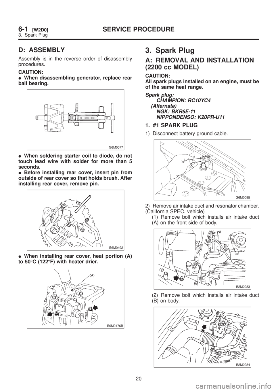
1. #1 SPARK PLUG
1) Disconnect battery ground cable.
G6M0095
2) Remove air intake duct and resonator chamber.
(California SPEC. vehicle)
(1) Remove bolt which installs air intake duct
(A) on the front side of body.
B2M2283
(2) Remove bolt which installs air intake duct
(B) on body.
B2M2284
20
6-1[W2D0]SERVICE PROCEDURE
3. Spark Plug
Page 1202 of 1456

D: ASSEMBLY
Assembly is in the reverse order of disassembly
procedures.
CAUTION:
IWhen disassembling generator, replace rear
ball bearing.
G6M0077
IWhen soldering starter coil to diode, do not
touch lead wire with solder for more than 5
seconds.
IBefore installing rear cover, insert pin from
outside of rear cover so that holds brush. After
installing rear cover, remove pin.
B6M0492
IWhen installing rear cover, heat portion (A)
to 50ÉC (122ÉF) with heater drier.
B6M0476B
3. Spark Plug
A: REMOVAL AND INSTALLATION
(2200 cc MODEL)
CAUTION:
All spark plugs installed on an engine, must be
of the same heat range.
Spark plug:
CHAMPION: RC10YC4
(Alternate)
NGK: BKR6E-11
NIPPONDENSO: K20PR-U11
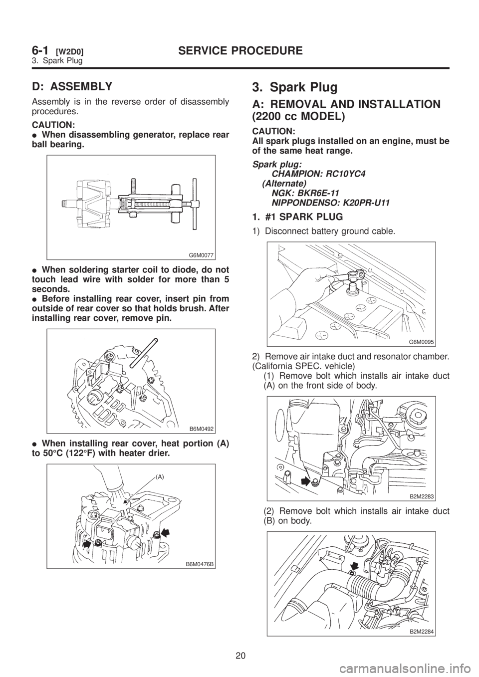
1. #1 SPARK PLUG
1) Disconnect battery ground cable.
G6M0095
2) Remove air intake duct and resonator chamber.
(California SPEC. vehicle)
(1) Remove bolt which installs air intake duct
(A) on the front side of body.
B2M2283
(2) Remove bolt which installs air intake duct
(B) on body.
B2M2284
20
6-1[W2D0]SERVICE PROCEDURE
3. Spark Plug
Page 1215 of 1456

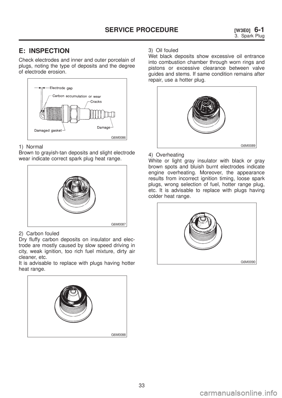
E: INSPECTION
Check electrodes and inner and outer porcelain of
plugs, noting the type of deposits and the degree
of electrode erosion.
G6M0086
1) Normal
Brown to grayish-tan deposits and slight electrode
wear indicate correct spark plug heat range.
G6M0087
2) Carbon fouled
Dry fluffy carbon deposits on insulator and elec-
trode are mostly caused by slow speed driving in
city, weak ignition, too rich fuel mixture, dirty air
cleaner, etc.
It is advisable to replace with plugs having hotter
heat range.
G6M0088
3) Oil fouled
Wet black deposits show excessive oil entrance
into combustion chamber through worn rings and
pistons or excessive clearance between valve
guides and stems. If same condition remains after
repair, use a hotter plug.
G6M0089
4) Overheating
White or light gray insulator with black or gray
brown spots and bluish burnt electrodes indicate
engine overheating. Moreover, the appearance
results from incorrect ignition timing, loose spark
plugs, wrong selection of fuel, hotter range plug,
etc. It is advisable to replace with plugs having
colder heat range.
G6M0090
33
[W3E0]6-1SERVICE PROCEDURE
3. Spark Plug