1999 SUBARU LEGACY display
[x] Cancel search: displayPage 35 of 1456

3. Engine Idle Speed
A: MEASUREMENT
1) Before checking idle speed, check the follow-
ing:
(1) Ensure that air cleaner element is free from
clogging, ignition timing is correct, spark plugs
are in good condition, and that hoses are con-
nected properly.
(2) Ensure that malfunction indicator light
(CHECK ENGINE light) does not illuminate.
2) Warm-up the engine.
3) Stop the engine, and turn ignition switch to
OFF.
4) When using SUBARU SELECT MONITOR;
NOTE:
For detailed operation procedures, refer to the
SUBARU SELECT MONITOR OPERATION
MANUAL.
(1) Insert the cartridge to SUBARU SELECT
MONITOR.
ST 24082AA090 CARTRIDGE
S2M0286A
(2) Connect SUBARU SELECT MONITOR to
the data link connector.
(3) Turn ignition switch to ON, and SUBARU
SELECT MONITOR switch to ON.
(4) Select {2. Each System Check} in Main
Menu.
(5) Select {EGI/EMPI} in Selection Menu.
(6) Select {1. Current Data Display & Save} in
EGI/EMPI Diagnosis.
(7) Select {1.12 Data Display} in Data Display
Menu.(8) Start the engine, and read engine idle
speed.
S2M0098
5) When using tachometer (Secondary pick-up
type).
(1) Attach the pick-up clip to No. 1 cylinder
spark plug cord.
(2) Start the engine, and read engine idle
speed.
B2M2011
NOTE:
IWhen using the OBD-II general scan tool, care-
fully read its operation manual.
IThis ignition system provides simultaneous igni-
tion for #1 and #2 plugs. It must be noted that
some tachometers may register twice that of actual
engine speed.
6) Check idle speed when unloaded. (With
headlights, heater fan, rear defroster, radiator fan,
air conditioning, etc. OFF)
Idle speed (No load and gears in neutral (MT),
or N or P (AT) position):
700
±100 rpm
7) Check idle speed when loaded. (Turn air con-
ditioning switch to |P¢rdquo;ON|P'ldquo; and oper-
ate compressor for at least one minute before
measurement.)
Idle speed [A/C ªONº, no load and gears in
neutral (MT) or N or P (AT) position]:
850
±50 rpm
3
[W3A0]2-2SERVICE PROCEDURE
3. Engine Idle Speed
Page 333 of 1456

(1) Insert the cartridge to Subaru Select Moni-
tor.
ST 24082AA090 CARTRIDGE
S2M0286A
(2) Connect Subaru Select Monitor to the data
link connector.
(3) Turn ignition switch to ON, and Subaru
Select Monitor switch to ON.
(4) Select {2. Each System Check} in Main
Menu.
(5) Select {EGI/EMPI} in Selection Menu.
(6) Select {1. Current Data Display & Save} in
EGI/EMPI Diagnosis.
(7) Select {1.12 Data Display} in Data Display
Menu.
(8) Adjust throttle position sensor to the proper
position to match with the following specifica-
tions.
Condition: Throttle fully closed
Throttle opening angle 0.00%
Throttle sensor voltage 0.50 V
S2M0098
(9) Tighten throttle position sensor holding
screws.
Tightening torque:
2.2
±0.2 N´m (0.22±0.02 kg-m, 1.6±0.1 ft-lb)
B2M2759
2. 2200 cc EXCEPT CALIFORNIA SPEC.
VEHICLES
1) Turn ignition switch to OFF.
2) Loosen throttle position sensor holding screws.
B2M2761
3) When using voltage meter;
(1) Take out ECM.
(2) Turn ignition switch to ON.
(3) Adjust throttle position sensor to the proper
position to allow the voltage signal to ECM to be
in specification.
Connector & terminal / Specified voltage
(B136) No. 15 Ð (B136) No. 17 / 0.45 Ð
0.55 V
[Fully closed.]
B2M2760
70
2-7[W9B2]SERVICE PROCEDURE
9. Throttle Position Sensor
Page 334 of 1456

(4) Tighten throttle position sensor holding
screws.
Tightening torque:
2.2
±0.2 N´m (0.22±0.02 kg-m, 1.6±0.1 ft-lb)
B2M2761
4) When using Subaru Select Monitor;
NOTE:
For detailed operation procedures, refer to the
Subaru Select Monitor Operation Manual.
(1) Insert the cartridge to Subaru Select Moni-
tor.
ST 24082AA090 CARTRIDGE
S2M0286A
(2) Connect Subaru Select Monitor to the data
link connector.
(3) Turn ignition switch to ON, and Subaru
Select Monitor switch to ON.
(4) Select {2. Each System Check} in Main
Menu.
(5) Select {EGI/EMPI} in Selection Menu.
(6) Select {1. Current Data Display & Save} in
EGI/EMPI Diagnosis.
(7) Select {1.12 Data Display} in Data Display
Menu.(8) Adjust throttle position sensor to the proper
position to match with the following specifica-
tions.
Condition: Throttle fully closed
Throttle opening angle 0.00%
Throttle sensor voltage 0.50 V
S2M0098
(9) Tighten throttle position sensor holding
screws.
Tightening torque:
2.2
±0.2 N´m (0.22±0.02 kg-m, 1.6±0.1 ft-lb)
B2M2761
3. 2500 cc MODEL
1) Turn ignition switch to OFF.
2) Loosen throttle position sensor holding screws.
S2M0133
3) When using voltage meter;
(1) Take out ECM.
(2) Turn ignition switch to ON.
71
[W9B3]2-7SERVICE PROCEDURE
9. Throttle Position Sensor
Page 335 of 1456

(3) Adjust throttle position sensor to the proper
position to allow the voltage signal to ECM to be
in specification.
Connector & terminal /
(B84) No. 6 Ð (B84) No. 20
Specified voltage /
0.45 Ð 0.55 V [Fully closed.]
S2M0097
(4) Tighten throttle position sensor holding
screws.
Tightening torque:
2.2
±0.2 N´m (0.22±0.02 kg-m, 1.6±0.1 ft-lb)
S2M0133
4) When using Subaru Select Monitor;
NOTE:
For detailed operation procedures, refer to the
Subaru Select Monitor Operation Manual.
(1) Insert the cartridge to Subaru Select Moni-
tor.
ST 24082AA090 CARTRIDGE
S2M0286A
(2) Connect Subaru Select Monitor to the data
link connector.(3) Turn ignition switch to ON, and Subaru
Select Monitor switch to ON.
(4) Select {2. Each System Check} in Main
Menu.
(5) Select {EGI/EMPI} in Selection Menu.
(6) Select {1. Current Data Display & Save} in
EGI/EMPI Diagnosis.
(7) Select {1.12 Data Display} in Data Display
Menu.
(8) Adjust throttle position sensor to the proper
position to match with the following specifica-
tions.
Condition: Throttle fully closed
Throttle opening angle 0.00%
Throttle sensor voltage 0.50 V
S2M0098
(9) Tighten throttle position sensor holding
screws.
Tightening torque:
2.2
±0.2 N´m (0.22±0.02 kg-m, 1.6±0.1 ft-lb)
S2M0133
72
2-7[W9B3]SERVICE PROCEDURE
9. Throttle Position Sensor
Page 342 of 1456

3) Disconnect air by-pass hose from air intake
duct.
S2M0102A
4) Slowly pour one can (16 oz) of cleaner into by-
pass air hole.
Cleaner:
Part No. 1050002 GM Top Engine Cleaner
Part No. X66-A AC Delco Carburetor
Tune-up Conditioner
S2M0103
5) Leave the engine running for five minutes.
NOTE:
Let white smoke come out from muffler until the
cleaner is used up.
6) Stop the engine.
7) Release the throttle valve.
8) Connect air by-pass hose to air intake duct.
S2M0102A
9) Check duty ratio of idle air control solenoid
valve using Subaru Select Monitor.
NOTE:
For detailed operation procedures, refer to the
Subaru Select Monitor Operation Manual.(1) Insert the cartridge to Subaru Select Moni-
tor.
ST 24082AA090 CARTRIDGE
S2M0286A
(2) Connect Subaru Select Monitor to the data
link connector.
(3) Turn ignition switch to ON, and Subaru
Select Monitor switch to ON.
(4) Select {2. Each System Check} in Main
Menu.
(5) Select {EGI/EMPI} in Selection Menu.
(6) Select {1. Current Data Display & Save} in
EGI/EMPI Diagnosis.
(7) Select {1.12 Data Display} in Data Display
Menu.
(8) Adjust throttle position sensor to the proper
position to match with the following specifica-
tion.
ISC valve duty ratio: 25 Ð 40%
S2M0098
78
2-7[W12B0]SERVICE PROCEDURE
12. Idle Air Control Solenoid Valve
Page 935 of 1456

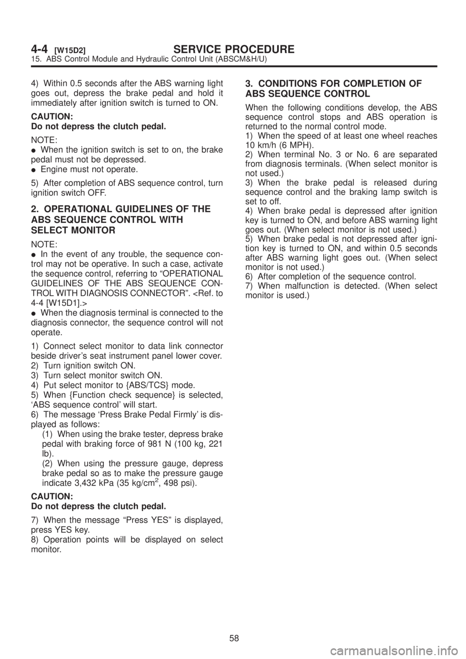
4) Within 0.5 seconds after the ABS warning light
goes out, depress the brake pedal and hold it
immediately after ignition switch is turned to ON.
CAUTION:
Do not depress the clutch pedal.
NOTE:
IWhen the ignition switch is set to on, the brake
pedal must not be depressed.
IEngine must not operate.
5) After completion of ABS sequence control, turn
ignition switch OFF.
2. OPERATIONAL GUIDELINES OF THE
ABS SEQUENCE CONTROL WITH
SELECT MONITOR
NOTE:
IIn the event of any trouble, the sequence con-
trol may not be operative. In such a case, activate
the sequence control, referring to ªOPERATIONAL
GUIDELINES OF THE ABS SEQUENCE CON-
TROL WITH DIAGNOSIS CONNECTORº.
IWhen the diagnosis terminal is connected to the
diagnosis connector, the sequence control will not
operate.
1) Connect select monitor to data link connector
beside driver's seat instrument panel lower cover.
2) Turn ignition switch ON.
3) Turn select monitor switch ON.
4) Put select monitor to {ABS/TCS} mode.
5) When {Function check sequence} is selected,
`ABS sequence control' will start.
6) The message `Press Brake Pedal Firmly' is dis-
played as follows:
(1) When using the brake tester, depress brake
pedal with braking force of 981 N (100 kg, 221
lb).
(2) When using the pressure gauge, depress
brake pedal so as to make the pressure gauge
indicate 3,432 kPa (35 kg/cm
2, 498 psi).
CAUTION:
Do not depress the clutch pedal.
7) When the message ªPress YESº is displayed,
press YES key.
8) Operation points will be displayed on select
monitor.
3. CONDITIONS FOR COMPLETION OF
ABS SEQUENCE CONTROL
When the following conditions develop, the ABS
sequence control stops and ABS operation is
returned to the normal control mode.
1) When the speed of at least one wheel reaches
10 km/h (6 MPH).
2) When terminal No. 3 or No. 6 are separated
from diagnosis terminals. (When select monitor is
not used.)
3) When the brake pedal is released during
sequence control and the braking lamp switch is
set to off.
4) When brake pedal is depressed after ignition
key is turned to ON, and before ABS warning light
goes out. (When select monitor is not used.)
5) When brake pedal is not depressed after igni-
tion key is turned to ON, and within 0.5 seconds
after ABS warning light goes out. (When select
monitor is not used.)
6) After completion of the sequence control.
7) When malfunction is detected. (When select
monitor is used.)
58
4-4[W15D2]SERVICE PROCEDURE
15. ABS Control Module and Hydraulic Control Unit (ABSCM&H/U)
Page 940 of 1456

C: INSPECTION WITH SELECT
MONITOR
16C1 : CHECK G SENSOR.
1) Turn ignition switch to OFF.
2) Connect select monitor connector to data link
connector.
3) Turn select monitor into {ABS/TCS} mode.
4) Set the display in the {Current Data Display &
Save} mode.
5) Read the G sensor output voltage.
:Is the indicated reading 2.3±0.2 V
when the vehicle is in horizontal
position?
: Go to step16C2.
: Replace G sensor.
16C2 : CHECK G SENSOR.
1) Remove console box.
2) Remove G sensor from vehicle. (Do not discon-
nect connector.)
3) Read the select monitor display.
B4M0917A
:Is the indicated reading 3.9±0.2 V
when G sensor is inclined forwards
to 90É?
: Go to step16C3.
: Replace G sensor.16C3 : CHECK G SENSOR.
Read the select monitor display.
B4M0918A
:Is the indicated reading 0.7±0.2 V
when G sensor is inclined backwards
to 90É?
: G sensor is normal.
: Replace G sensor.
D: INSTALLATION
1. FRONT ABS SENSOR
1) Install tone wheel on hub, then install housing
on hub assembly.
2) Temporarily install front ABS sensor on hous-
ing.
CAUTION:
Be careful not to strike ABS sensor's pole
piece and tone wheel's teeth against adjacent
metal parts during installation.
B4M1183A
3) Install front drive shaft to hub spline.
62
4-4[W16C1]SERVICE PROCEDURE
16. G Sensor
Page 986 of 1456

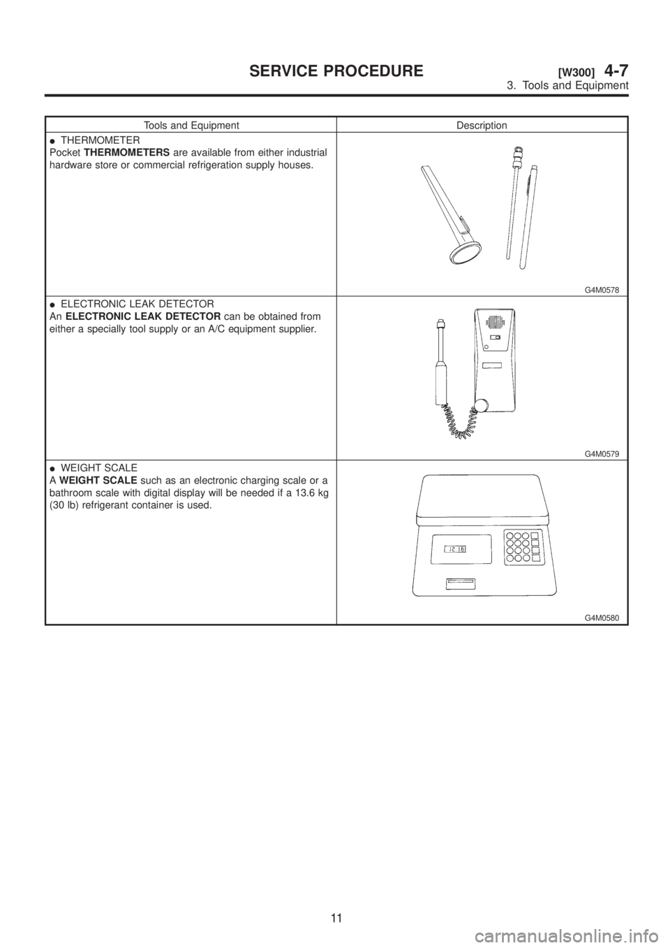
Tools and Equipment Description
ITHERMOMETER
PocketTHERMOMETERSare available from either industrial
hardware store or commercial refrigeration supply houses.
G4M0578
IELECTRONIC LEAK DETECTOR
AnELECTRONIC LEAK DETECTORcan be obtained from
either a specially tool supply or an A/C equipment supplier.
G4M0579
IWEIGHT SCALE
AWEIGHT SCALEsuch as an electronic charging scale or a
bathroom scale with digital display will be needed if a 13.6 kg
(30 lb) refrigerant container is used.
G4M0580
11
[W300]4-7SERVICE PROCEDURE
3. Tools and Equipment