1999 SUBARU LEGACY brake pads
[x] Cancel search: brake padsPage 868 of 1456

Fluid leaking area Possible cause Corrective action
Leakage from connecting portions of
pipes and hoses, numbered with (1) thru
(9) in figureInsufficient tightening of flare nut, catch-
ing dirt or the like, damage to flare or
flare nutLoosen and retighten, if ineffective,
replace.
Poor insertion of hose, poor clamping Retighten or replace clamp.
Damaged O-ring Replace O-ring pipe or hose with new
one, if ineffective, replace gearbox also.
Leakage from hose (10) and (11) in fig-
ureCrack or damage in hose Replace with a new one.
Crack or damage in hose hardware Replace with a new one.
Leakage from surrounding of cast iron
portion of oil pump (12) and (13) in fig-
ureDamaged O-ring Replace O-ring.
Damaged gasket Replace gasket.
Leakage from oil tank, (14) and (15) in
figureCrack in oil tank, (14) Replace oil tank.
Damaged O-ring, (15) Replace O-ring.
Leakage from filler neck (16) Damaged cap packing Replace cap.
Crack in root of filler neck Replace oil tank.
High fluid level *1 Adjust fluid level.
Leakage from surrounding of power cyl-
inder of gearbox, (17) in figureDamaged oil seal Replace oil seal.
Leakage from control valve of gearbox,
(18) and (19) in figureDamaged packing or oil seal Replace problem parts.
Damage in control valve Replace control valve.
*1 Fluid level is specified at optimum position (range) for ordinary use. Accordingly, if the vehicle is used often under hard
conditions such as on very rough roads or in mountainous areas, fluid may bleed out from cap air vent hole. This is not
a problem. If a customer complains strongly and is not likely to be satisfied with the leakage, lower the fluid level to the
extent that fluid will not bleed out under the conditions described, and have the customer check the fluid level and its
quality more frequency than usual.
E: NOISE AND VIBRATION
CAUTION:
Don't keep the relief valve operated over 5 sec-
onds at any time or inner parts of the oil pump
may be damaged due to rapid increase of fluid
temperature.
NOTE:
IGrinding noise may be heard immediately after
the engine start in extremely cold condition. In this
case, if the noise goes off during warm-up there is
no abnormal function in the system. This is due to
the fluid characteristic in extremely cold condition.
IOil pump makes whine or growl noise slightly
due to its mechanism. Even if the noise can be
heard when steering wheel is turned at stand still
there is no abnormal function in the system pro-
vided that the noise eliminates when the vehicle is
running.
IWhen stopping with service brake and/or park-
ing brake applied, power steering can be operated
easily due to its light steering effort. If doing so, thedisk rotates slightly and makes creaking noise. The
noise is generated by creaking between the disk
and pads. If the noise goes off when the brake is
released, there is no abnormal function in the sys-
tem.
IThere may be a little vibration around the steer-
ing devices when turning steering wheel at
standstill, even though the component parts are
properly adjusted and have no defects.
Hydraulic systems are likely to generate this kind
of vibration as well as working noise and fluid noise
because of combined conditions, i.e., road surface
and tire surface, engine speed and turning speed
of steering wheel, fluid temperature and braking
condition.
This phenomena does not indicate there is some
abnormal function in the system.
The vibration can be known when steering wheel
is turned repeatedly at various speeds from slow to
rapid step by step with parking brake applied on
concrete road and in ªDº range for automatic trans-
mission vehicle.
Trouble Possible cause Corrective action
Hiss noise (continuous)
While engine is running.Relief valve emits operating sound when steering wheel is
completely turned in either direction. (Don't keep this condition
over 5 seconds.)Normal
Relief valve emits operating sound when steering wheel is not
turned. This means that the relief valve is faulty.Defective
Replace oil pump.
74
4-3[K1E0]DIAGNOSTICS
1. Power Steering
Page 889 of 1456

1. Front Disc Brake
A: ON-CAR SERVICE
1. PAD
1) Remove lock pin.
2) Raise caliper body.
3) Remove pad.
B4M1167
4) Check pad thickness A.
B4M1168A
Pad thickness
(including back metal)
mm (in)Standard value 17 (0.67)
Wear limit 7.5 (0.295)
CAUTION:
IAlways replace the pads for both the left and
right wheels at the same time. Also replace pad
clips if they are twisted or worn.
IA wear indicator is provided on the inner
disc brake pad. If the pad wears down to such
an extent that the end of the wear indicator
contacts the disc rotor, a squeaking sound is
produced as the wheel rotates. If this sound is
heard, replace the pad.
IReplace pad if there is oil or grease on it.5) Apply thin coat of PBC GREASE (Part No.
003607000) to the frictional portion between pad
and pad clip.
B4M1169A
6) Install pads on support.
7) Install caliper body on support.
NOTE:
If it is difficult to push piston during pad
replacement, loosen air bleeder to facilitate work.
2. DISC ROTOR
1) Install disc rotor by tightening the five wheel
nuts.
2) Set a dial gauge on the disc rotor. Turn disc
rotor to check runout.
G4M0364
NOTE:
Make sure that dial gauge is set 5 mm (0.20 in)
inward of rotor outer perimeter.
Disc rotor runout limit:
0.075 mm (0.0030 in)
18
4-4[W1A1]SERVICE PROCEDURE
1. Front Disc Brake
Page 895 of 1456
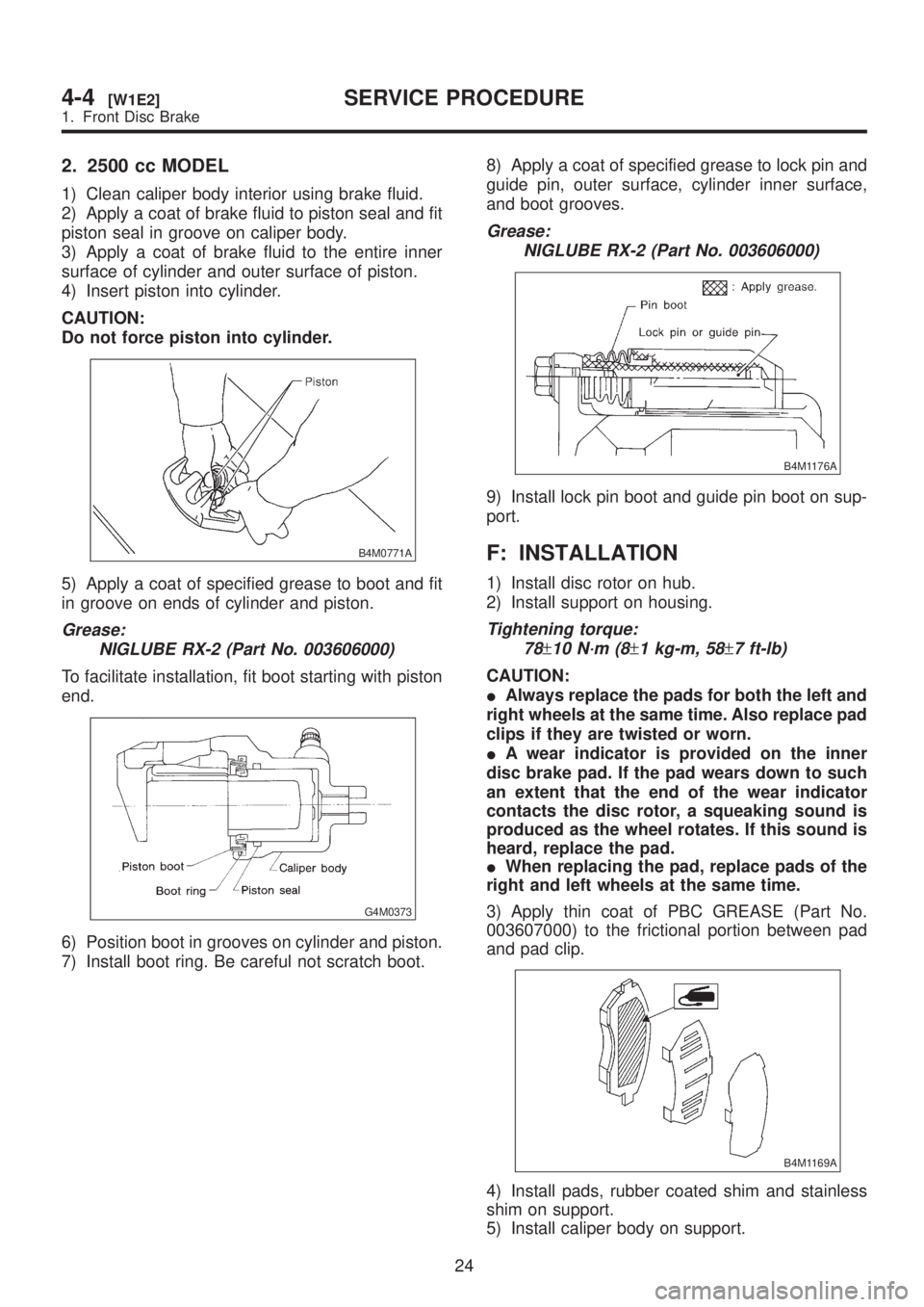
2. 2500 cc MODEL
1) Clean caliper body interior using brake fluid.
2) Apply a coat of brake fluid to piston seal and fit
piston seal in groove on caliper body.
3) Apply a coat of brake fluid to the entire inner
surface of cylinder and outer surface of piston.
4) Insert piston into cylinder.
CAUTION:
Do not force piston into cylinder.
B4M0771A
5) Apply a coat of specified grease to boot and fit
in groove on ends of cylinder and piston.
Grease:
NIGLUBE RX-2 (Part No. 003606000)
To facilitate installation, fit boot starting with piston
end.
G4M0373
6) Position boot in grooves on cylinder and piston.
7) Install boot ring. Be careful not scratch boot.8) Apply a coat of specified grease to lock pin and
guide pin, outer surface, cylinder inner surface,
and boot grooves.
Grease:
NIGLUBE RX-2 (Part No. 003606000)
B4M1176A
9) Install lock pin boot and guide pin boot on sup-
port.
F: INSTALLATION
1) Install disc rotor on hub.
2) Install support on housing.
Tightening torque:
78
±10 N´m (8±1 kg-m, 58±7 ft-lb)
CAUTION:
IAlways replace the pads for both the left and
right wheels at the same time. Also replace pad
clips if they are twisted or worn.
IA wear indicator is provided on the inner
disc brake pad. If the pad wears down to such
an extent that the end of the wear indicator
contacts the disc rotor, a squeaking sound is
produced as the wheel rotates. If this sound is
heard, replace the pad.
IWhen replacing the pad, replace pads of the
right and left wheels at the same time.
3) Apply thin coat of PBC GREASE (Part No.
003607000) to the frictional portion between pad
and pad clip.
B4M1169A
4) Install pads, rubber coated shim and stainless
shim on support.
5) Install caliper body on support.
24
4-4[W1E2]SERVICE PROCEDURE
1. Front Disc Brake
Page 898 of 1456
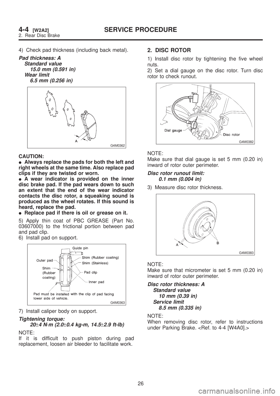
4) Check pad thickness (including back metal).
Pad thickness: A
Standard value
15.0 mm (0.591 in)
Wear limit
6.5 mm (0.256 in)
G4M0362
CAUTION:
IAlways replace the pads for both the left and
right wheels at the same time. Also replace pad
clips if they are twisted or worn.
IA wear indicator is provided on the inner
disc brake pad. If the pad wears down to such
an extent that the end of the wear indicator
contacts the disc rotor, a squeaking sound is
produced as the wheel rotates. If this sound is
heard, replace the pad.
IReplace pad if there is oil or grease on it.
5) Apply thin coat of PBC GREASE (Part No.
03607000) to the frictional portion between pad
and pad clip.
6) Install pad on support.
G4M0363
7) Install caliper body on support.
Tightening torque:
20
±4 N´m (2.0±0.4 kg-m, 14.5±2.9 ft-lb)
NOTE:
If it is difficult to push piston during pad
replacement, loosen air bleeder to facilitate work.
2. DISC ROTOR
1) Install disc rotor by tightening the five wheel
nuts.
2) Set a dial gauge on the disc rotor. Turn disc
rotor to check runout.
G4M0382
NOTE:
Make sure that dial gauge is set 5 mm (0.20 in)
inward of rotor outer perimeter.
Disc rotor runout limit:
0.1 mm (0.004 in)
3) Measure disc rotor thickness.
G4M0383
NOTE:
Make sure that micrometer is set 5 mm (0.20 in)
inward of rotor outer perimeter.
Disc rotor thickness: A
Standard value
10 mm (0.39 in)
Service limit
8.5 mm (0.335 in)
NOTE:
When removing disc rotor, refer to instructions
under Parking Brake.
26
4-4[W2A2]SERVICE PROCEDURE
2. Rear Disc Brake
Page 901 of 1456
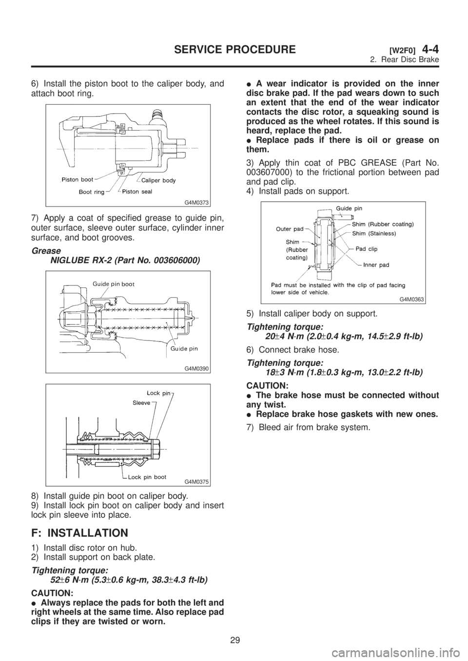
6) Install the piston boot to the caliper body, and
attach boot ring.
G4M0373
7) Apply a coat of specified grease to guide pin,
outer surface, sleeve outer surface, cylinder inner
surface, and boot grooves.
Grease
NIGLUBE RX-2 (Part No. 003606000)
G4M0390
G4M0375
8) Install guide pin boot on caliper body.
9) Install lock pin boot on caliper body and insert
lock pin sleeve into place.
F: INSTALLATION
1) Install disc rotor on hub.
2) Install support on back plate.
Tightening torque:
52
±6 N´m (5.3±0.6 kg-m, 38.3±4.3 ft-lb)
CAUTION:
IAlways replace the pads for both the left and
right wheels at the same time. Also replace pad
clips if they are twisted or worn.IA wear indicator is provided on the inner
disc brake pad. If the pad wears down to such
an extent that the end of the wear indicator
contacts the disc rotor, a squeaking sound is
produced as the wheel rotates. If this sound is
heard, replace the pad.
IReplace pads if there is oil or grease on
them.
3) Apply thin coat of PBC GREASE (Part No.
003607000) to the frictional portion between pad
and pad clip.
4) Install pads on support.
G4M0363
5) Install caliper body on support.
Tightening torque:
20
±4 N´m (2.0±0.4 kg-m, 14.5±2.9 ft-lb)
6) Connect brake hose.
Tightening torque:
18
±3 N´m (1.8±0.3 kg-m, 13.0±2.2 ft-lb)
CAUTION:
IThe brake hose must be connected without
any twist.
IReplace brake hose gaskets with new ones.
7) Bleed air from brake system.
29
[W2F0]4-4SERVICE PROCEDURE
2. Rear Disc Brake
Page 954 of 1456

4) Remove two bolts and four nuts which secure
brake pedal to pedal.
G4M0324
4. BRAKE AND CLUTCH PEDAL (2500 cc
MODEL)
1) Remove steering bolts.
2) Raise vehicle on hoist and remove the two bolts
which secure steering unit to underside of body.
3) Lower vehicle to floor.
4) Remove instrument panel lower cover from
instrument panel.
5) Disconnect the following parts from pedal
bracket.
IOperating rod of brake booster
IElectrical connectors (for stop light switch, etc.)
6) Remove clevis pin which secures lever to push
rod.
7) Remove nut which secures clutch master cylin-
der.
8) Remove steering assembly.
9) Remove bolts and nuts which secure brake and
clutch pedals, and remove pedal assembly.
C: INSPECTION
1. BRAKE AND CLUTCH PEDALS
Move brake and clutch pedal pads in the lateral
direction with a force of approximately 10 N (1 kg,
2 lb) to ensure pedal deflection is in specified
range.
Deflection of brake and clutch pedal:
Service limit
5.0 mm (0.197 in) or less
CAUTION:
If excessive deflection is noted, replace bush-
ings with new ones.
S4M0135A
G4M0326
9
[W1C1]4-5SERVICE PROCEDURE
1. Pedal