1999 SUBARU LEGACY remove seats
[x] Cancel search: remove seatsPage 170 of 1456
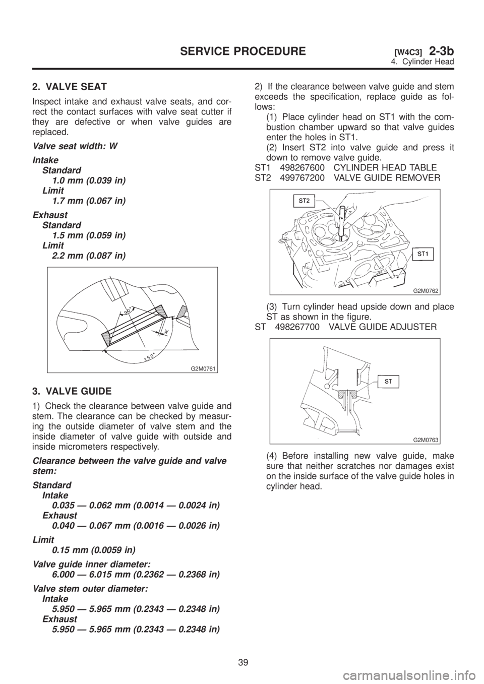
2. VALVE SEAT
Inspect intake and exhaust valve seats, and cor-
rect the contact surfaces with valve seat cutter if
they are defective or when valve guides are
replaced.
Valve seat width: W
Intake
Standard
1.0 mm (0.039 in)
Limit
1.7 mm (0.067 in)
Exhaust
Standard
1.5 mm (0.059 in)
Limit
2.2 mm (0.087 in)
G2M0761
3. VALVE GUIDE
1) Check the clearance between valve guide and
stem. The clearance can be checked by measur-
ing the outside diameter of valve stem and the
inside diameter of valve guide with outside and
inside micrometers respectively.
Clearance between the valve guide and valve
stem:
Standard
Intake
0.035 Ð 0.062 mm (0.0014 Ð 0.0024 in)
Exhaust
0.040 Ð 0.067 mm (0.0016 Ð 0.0026 in)
Limit
0.15 mm (0.0059 in)
Valve guide inner diameter:
6.000 Ð 6.015 mm (0.2362 Ð 0.2368 in)
Valve stem outer diameter:
Intake
5.950 Ð 5.965 mm (0.2343 Ð 0.2348 in)
Exhaust
5.950 Ð 5.965 mm (0.2343 Ð 0.2348 in)
2) If the clearance between valve guide and stem
exceeds the specification, replace guide as fol-
lows:
(1) Place cylinder head on ST1 with the com-
bustion chamber upward so that valve guides
enter the holes in ST1.
(2) Insert ST2 into valve guide and press it
down to remove valve guide.
ST1 498267600 CYLINDER HEAD TABLE
ST2 499767200 VALVE GUIDE REMOVER
G2M0762
(3) Turn cylinder head upside down and place
ST as shown in the figure.
ST 498267700 VALVE GUIDE ADJUSTER
G2M0763
(4) Before installing new valve guide, make
sure that neither scratches nor damages exist
on the inside surface of the valve guide holes in
cylinder head.
39
[W4C3]2-3bSERVICE PROCEDURE
4. Cylinder Head
Page 439 of 1456
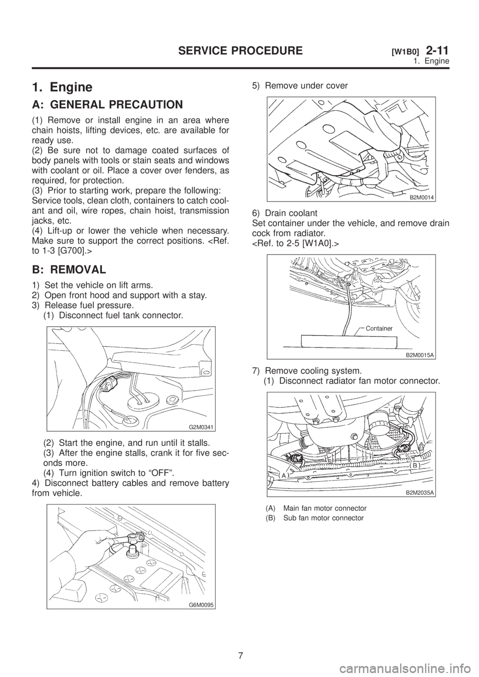
1. Engine
A: GENERAL PRECAUTION
(1) Remove or install engine in an area where
chain hoists, lifting devices, etc. are available for
ready use.
(2) Be sure not to damage coated surfaces of
body panels with tools or stain seats and windows
with coolant or oil. Place a cover over fenders, as
required, for protection.
(3) Prior to starting work, prepare the following:
Service tools, clean cloth, containers to catch cool-
ant and oil, wire ropes, chain hoist, transmission
jacks, etc.
(4) Lift-up or lower the vehicle when necessary.
Make sure to support the correct positions.
B: REMOVAL
1) Set the vehicle on lift arms.
2) Open front hood and support with a stay.
3) Release fuel pressure.
(1) Disconnect fuel tank connector.
G2M0341
(2) Start the engine, and run until it stalls.
(3) After the engine stalls, crank it for five sec-
onds more.
(4) Turn ignition switch to ªOFFº.
4) Disconnect battery cables and remove battery
from vehicle.
G6M0095
5) Remove under cover
B2M0014
6) Drain coolant
Set container under the vehicle, and remove drain
cock from radiator.
B2M0015A
7) Remove cooling system.
(1) Disconnect radiator fan motor connector.
B2M2035A
(A) Main fan motor connector
(B) Sub fan motor connector
7
[W1B0]2-11SERVICE PROCEDURE
1. Engine
Page 453 of 1456

2. Transmission
A: GENERAL PRECAUTION
(1) Remove or install transmission in an area
where chain hoists, lifting devices, etc. are avail-
able for ready use.
(2) Be sure not to damage coated surfaces of
body panels with tools or stain seats and windows
with coolant or oil. Place a cover over fenders, as
required, for protection.
(3) Prior to starting work, prepare the following:
Service tools, clean cloth, containers to catch cool-
ant and oil, wire ropes, chain hoist, transmission
jacks, etc.
(4) Lift-up or lower the vehicle when necessary.
Make sure to support the correct positions.
B: REMOVAL
1) Open front hood fully, and support with stay.
2) Disconnect battery ground terminal.
3) Remove air intake duct and chamber. (Except
2200 cc California spec. vehicles)
4) Install air intake duct with air cleaner case.
(2200 cc California spec. vehicles)
5) Remove chamber stay.
IMT vehicles
S2M0210
IAT vehicles
S6M0023
6) Disconnect the following connectors.
(1) Oxygen sensor connector
S2M0200A
(1) Front oxygen sensor connector
(2) Rear oxygen sensor connector (California spec.
vehicles)
(2) Transmission harness connector (AT
vehicles)
S2M0212A
(3) Transmission ground terminal
(4) Neutral position switch connector (MT
vehicles)
(5) Back-up light switch connector (MT
vehicles)
B2M0337
21
[W2B0]2-11SERVICE PROCEDURE
2. Transmission
Page 1063 of 1456
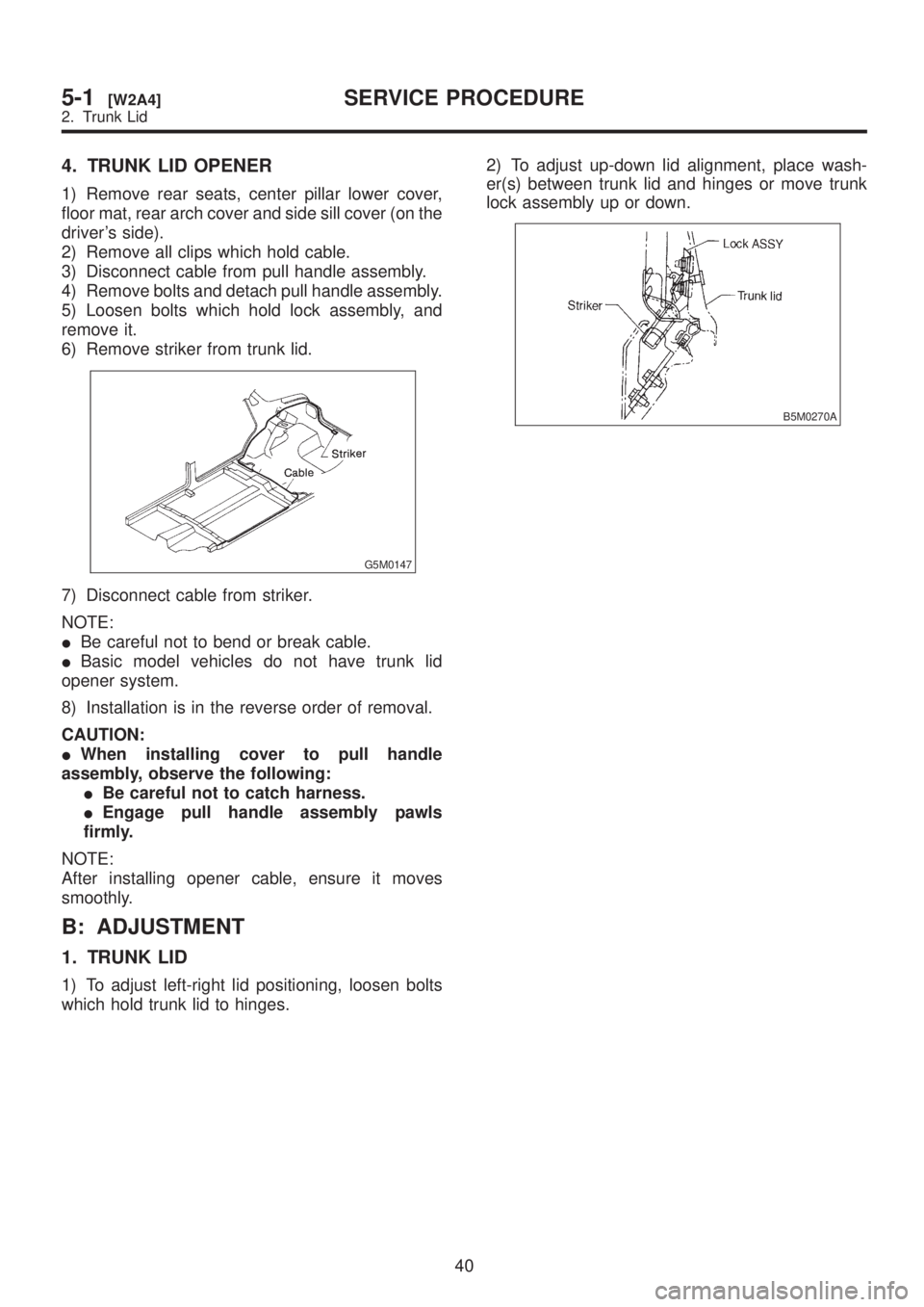
4. TRUNK LID OPENER
1) Remove rear seats, center pillar lower cover,
floor mat, rear arch cover and side sill cover (on the
driver's side).
2) Remove all clips which hold cable.
3) Disconnect cable from pull handle assembly.
4) Remove bolts and detach pull handle assembly.
5) Loosen bolts which hold lock assembly, and
remove it.
6) Remove striker from trunk lid.
G5M0147
7) Disconnect cable from striker.
NOTE:
IBe careful not to bend or break cable.
IBasic model vehicles do not have trunk lid
opener system.
8) Installation is in the reverse order of removal.
CAUTION:
IWhen installing cover to pull handle
assembly, observe the following:
IBe careful not to catch harness.
IEngage pull handle assembly pawls
firmly.
NOTE:
After installing opener cable, ensure it moves
smoothly.
B: ADJUSTMENT
1. TRUNK LID
1) To adjust left-right lid positioning, loosen bolts
which hold trunk lid to hinges.2) To adjust up-down lid alignment, place wash-
er(s) between trunk lid and hinges or move trunk
lock assembly up or down.
B5M0270A
40
5-1[W2A4]SERVICE PROCEDURE
2. Trunk Lid
Page 1064 of 1456
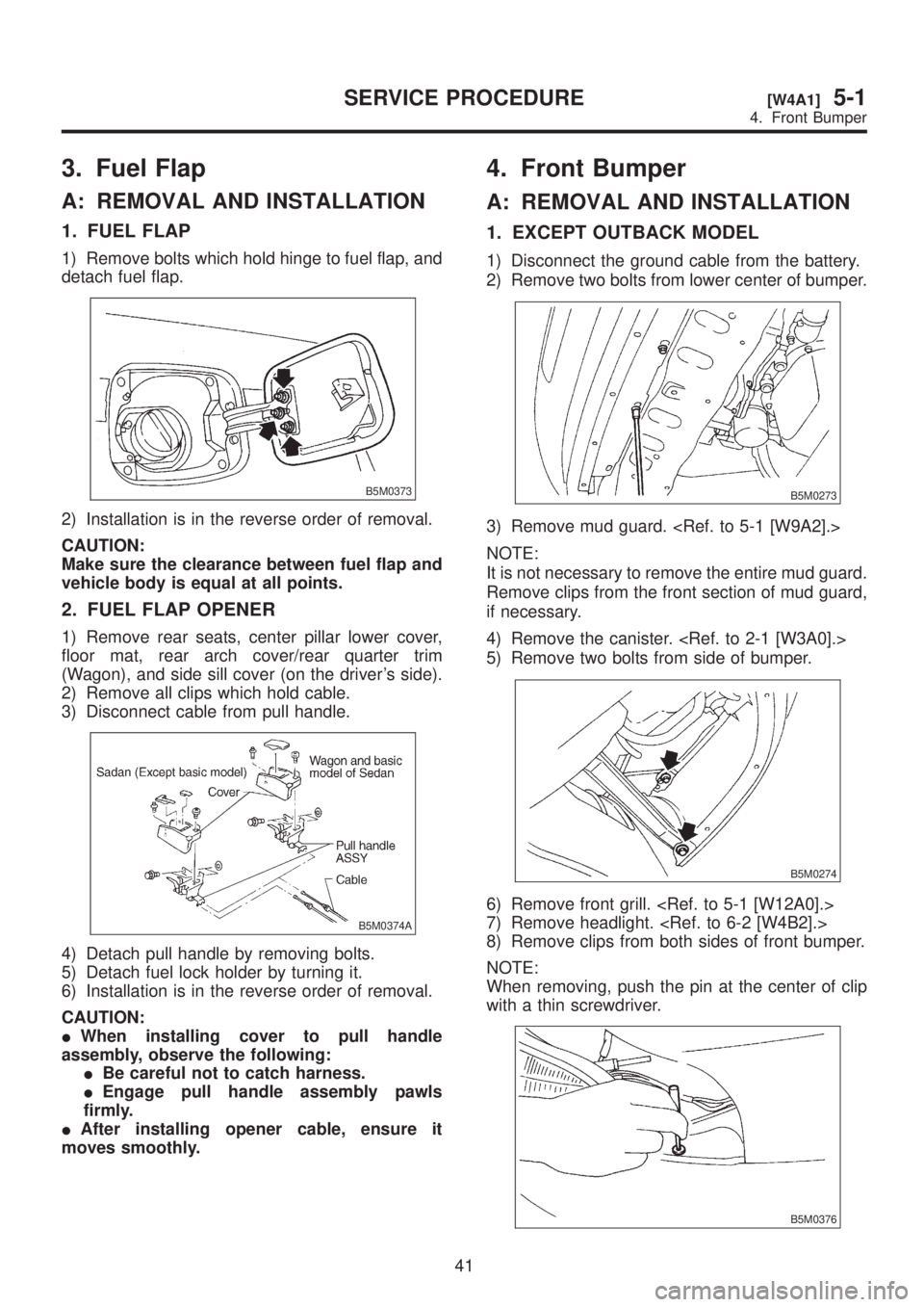
3. Fuel Flap
A: REMOVAL AND INSTALLATION
1. FUEL FLAP
1) Remove bolts which hold hinge to fuel flap, and
detach fuel flap.
B5M0373
2) Installation is in the reverse order of removal.
CAUTION:
Make sure the clearance between fuel flap and
vehicle body is equal at all points.
2. FUEL FLAP OPENER
1) Remove rear seats, center pillar lower cover,
floor mat, rear arch cover/rear quarter trim
(Wagon), and side sill cover (on the driver's side).
2) Remove all clips which hold cable.
3) Disconnect cable from pull handle.
B5M0374A
4) Detach pull handle by removing bolts.
5) Detach fuel lock holder by turning it.
6) Installation is in the reverse order of removal.
CAUTION:
IWhen installing cover to pull handle
assembly, observe the following:
IBe careful not to catch harness.
IEngage pull handle assembly pawls
firmly.
IAfter installing opener cable, ensure it
moves smoothly.
4. Front Bumper
A: REMOVAL AND INSTALLATION
1. EXCEPT OUTBACK MODEL
1) Disconnect the ground cable from the battery.
2) Remove two bolts from lower center of bumper.
B5M0273
3) Remove mud guard.
NOTE:
It is not necessary to remove the entire mud guard.
Remove clips from the front section of mud guard,
if necessary.
4) Remove the canister.
5) Remove two bolts from side of bumper.
B5M0274
6) Remove front grill.
7) Remove headlight.
8) Remove clips from both sides of front bumper.
NOTE:
When removing, push the pin at the center of clip
with a thin screwdriver.
B5M0376
41
[W4A1]5-1SERVICE PROCEDURE
4. Front Bumper
Page 1065 of 1456
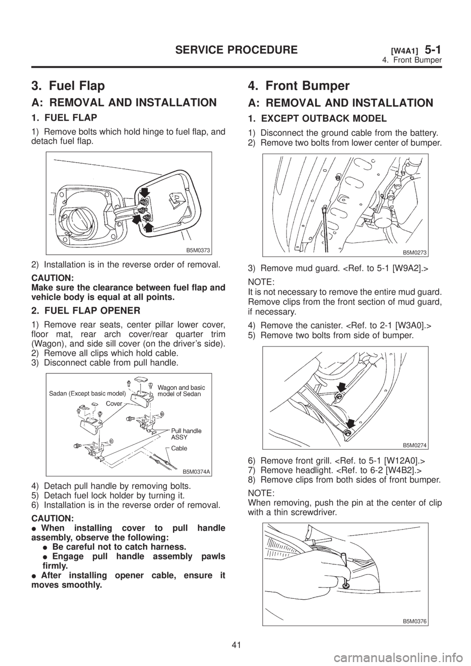
3. Fuel Flap
A: REMOVAL AND INSTALLATION
1. FUEL FLAP
1) Remove bolts which hold hinge to fuel flap, and
detach fuel flap.
B5M0373
2) Installation is in the reverse order of removal.
CAUTION:
Make sure the clearance between fuel flap and
vehicle body is equal at all points.
2. FUEL FLAP OPENER
1) Remove rear seats, center pillar lower cover,
floor mat, rear arch cover/rear quarter trim
(Wagon), and side sill cover (on the driver's side).
2) Remove all clips which hold cable.
3) Disconnect cable from pull handle.
B5M0374A
4) Detach pull handle by removing bolts.
5) Detach fuel lock holder by turning it.
6) Installation is in the reverse order of removal.
CAUTION:
IWhen installing cover to pull handle
assembly, observe the following:
IBe careful not to catch harness.
IEngage pull handle assembly pawls
firmly.
IAfter installing opener cable, ensure it
moves smoothly.
4. Front Bumper
A: REMOVAL AND INSTALLATION
1. EXCEPT OUTBACK MODEL
1) Disconnect the ground cable from the battery.
2) Remove two bolts from lower center of bumper.
B5M0273
3) Remove mud guard.
NOTE:
It is not necessary to remove the entire mud guard.
Remove clips from the front section of mud guard,
if necessary.
4) Remove the canister.
5) Remove two bolts from side of bumper.
B5M0274
6) Remove front grill.
7) Remove headlight.
8) Remove clips from both sides of front bumper.
NOTE:
When removing, push the pin at the center of clip
with a thin screwdriver.
B5M0376
41
[W4A1]5-1SERVICE PROCEDURE
4. Front Bumper