Page 452 of 1456
(5) Connect radiator inlet hose.
S2M0031
(6) Connect radiator outlet hose.
(7) Connect ATF cooler hoses. (AT vehicles)
B2M0016A
(8) Install reservoir tank.
(9) Install V-belt cover.
B2M2307
18) Install under cover.
B2M0014
19) Install battery in the vehicle, and connect
cables.
20) Fill coolant.
Engine coolant capacity;
5.8
(6.1 US qt, 5.1 lmp qt)
21) Charge A/C system with refrigerant.
22) Remove front hood stay, and close front hood.
23) Take off the vehicle from lift arms.
20
2-11[W1C0]SERVICE PROCEDURE
1. Engine
Page 698 of 1456

NOTE:
When installing rear differential front member, do
not confuse the installation sequence of the upper
and lower stoppers.
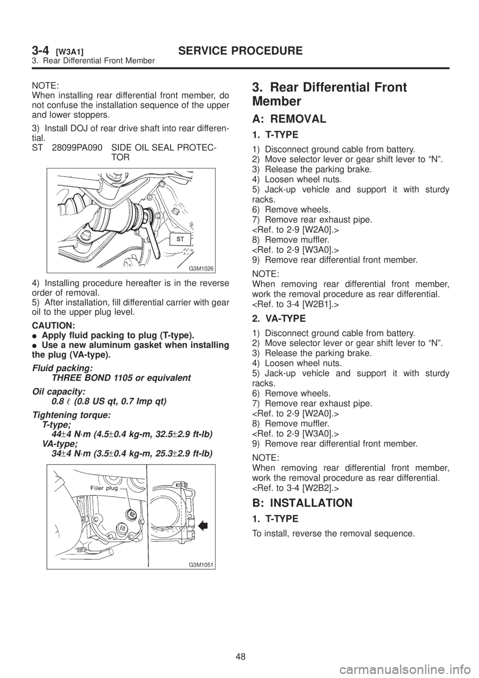
3) Install DOJ of rear drive shaft into rear differen-
tial.
ST 28099PA090 SIDE OIL SEAL PROTEC-
TOR
G3M1026
4) Installing procedure hereafter is in the reverse
order of removal.
5) After installation, fill differential carrier with gear
oil to the upper plug level.
CAUTION:
IApply fluid packing to plug (T-type).
IUse a new aluminum gasket when installing
the plug (VA-type).
Fluid packing:
THREE BOND 1105 or equivalent
Oil capacity:
0.8
(0.8 US qt, 0.7 Imp qt)
Tightening torque:
T-type;
44
±4 N´m (4.5±0.4 kg-m, 32.5±2.9 ft-lb)
VA-type;
34
±4 N´m (3.5±0.4 kg-m, 25.3±2.9 ft-lb)
G3M1051
3. Rear Differential Front
Member
A: REMOVAL
1. T-TYPE
1) Disconnect ground cable from battery.
2) Move selector lever or gear shift lever to ªNº.
3) Release the parking brake.
4) Loosen wheel nuts.
5) Jack-up vehicle and support it with sturdy
racks.
6) Remove wheels.
7) Remove rear exhaust pipe.
8) Remove muffler.
9) Remove rear differential front member.
NOTE:
When removing rear differential front member,
work the removal procedure as rear differential.
2. VA-TYPE
1) Disconnect ground cable from battery.
2) Move selector lever or gear shift lever to ªNº.
3) Release the parking brake.
4) Loosen wheel nuts.
5) Jack-up vehicle and support it with sturdy
racks.
6) Remove wheels.
7) Remove rear exhaust pipe.
8) Remove muffler.
9) Remove rear differential front member.
NOTE:
When removing rear differential front member,
work the removal procedure as rear differential.
B: INSTALLATION
1. T-TYPE
To install, reverse the removal sequence.
48
3-4[W3A1]SERVICE PROCEDURE
3. Rear Differential Front Member
Page 699 of 1456

NOTE:
When installing rear differential front member, do
not confuse the installation sequence of the upper
and lower stoppers.
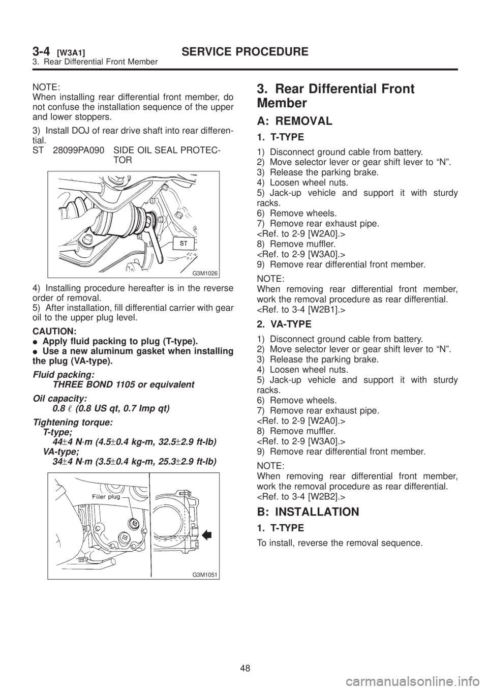
3) Install DOJ of rear drive shaft into rear differen-
tial.
ST 28099PA090 SIDE OIL SEAL PROTEC-
TOR
G3M1026
4) Installing procedure hereafter is in the reverse
order of removal.
5) After installation, fill differential carrier with gear
oil to the upper plug level.
CAUTION:
IApply fluid packing to plug (T-type).
IUse a new aluminum gasket when installing
the plug (VA-type).
Fluid packing:
THREE BOND 1105 or equivalent
Oil capacity:
0.8
(0.8 US qt, 0.7 Imp qt)
Tightening torque:
T-type;
44
±4 N´m (4.5±0.4 kg-m, 32.5±2.9 ft-lb)
VA-type;
34
±4 N´m (3.5±0.4 kg-m, 25.3±2.9 ft-lb)
G3M1051
3. Rear Differential Front
Member
A: REMOVAL
1. T-TYPE
1) Disconnect ground cable from battery.
2) Move selector lever or gear shift lever to ªNº.
3) Release the parking brake.
4) Loosen wheel nuts.
5) Jack-up vehicle and support it with sturdy
racks.
6) Remove wheels.
7) Remove rear exhaust pipe.
8) Remove muffler.
9) Remove rear differential front member.
NOTE:
When removing rear differential front member,
work the removal procedure as rear differential.
2. VA-TYPE
1) Disconnect ground cable from battery.
2) Move selector lever or gear shift lever to ªNº.
3) Release the parking brake.
4) Loosen wheel nuts.
5) Jack-up vehicle and support it with sturdy
racks.
6) Remove wheels.
7) Remove rear exhaust pipe.
8) Remove muffler.
9) Remove rear differential front member.
NOTE:
When removing rear differential front member,
work the removal procedure as rear differential.
B: INSTALLATION
1. T-TYPE
To install, reverse the removal sequence.
48
3-4[W3A1]SERVICE PROCEDURE
3. Rear Differential Front Member
Page 1189 of 1456

B: TEST
1. MAGNETIC SWITCH
CAUTION:
IThe following magnetic switch tests should
be performed with specified voltage applied.
IEach test should be conducted within 3 to 5
seconds. Power to be furnished should be one-
half the rated voltage.
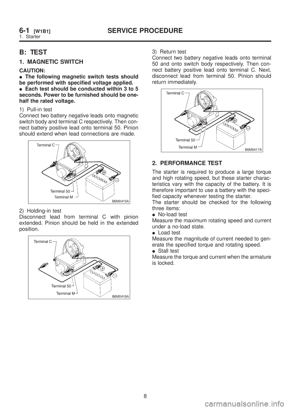
1) Pull-in test
Connect two battery negative leads onto magnetic
switch body and terminal C respectively. Then con-
nect battery positive lead onto terminal 50. Pinion
should extend when lead connections are made.
B6M0415A
2) Holding-in test
Disconnect lead from terminal C with pinion
extended. Pinion should be held in the extended
position.
B6M0416A
3) Return test
Connect two battery negative leads onto terminal
50 and onto switch body respectively. Then con-
nect battery positive lead onto terminal C. Next,
disconnect lead from terminal 50. Pinion should
return immediately.
B6M0417A
2. PERFORMANCE TEST
The starter is required to produce a large torque
and high rotating speed, but these starter charac-
teristics vary with the capacity of the battery. It is
therefore important to use a battery with the speci-
fied capacity whenever testing the starter.
The starter should be checked for the following
three items:
INo-load test
Measure the maximum rotating speed and current
under a no-load state.
ILoad test
Measure the magnitude of current needed to gen-
erate the specified torque and rotating speed.
IStall test
Measure the torque and current when the armature
is locked.
8
6-1[W1B1]SERVICE PROCEDURE
1. Starter
Page 1226 of 1456

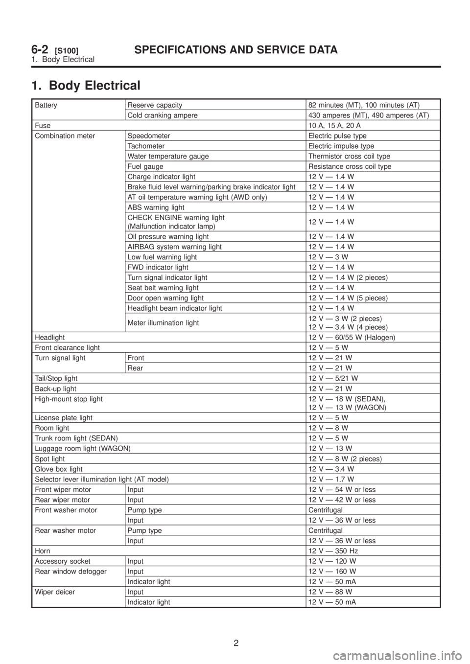
1. Body Electrical
Battery Reserve capacity 82 minutes (MT), 100 minutes (AT)
Cold cranking ampere 430 amperes (MT), 490 amperes (AT)
Fuse10 A, 15 A, 20 A
Combination meter Speedometer Electric pulse type
Tachometer Electric impulse type
Water temperature gauge Thermistor cross coil type
Fuel gauge Resistance cross coil type
Charge indicator light 12 V Ð 1.4 W
Brake fluid level warning/parking brake indicator light 12 V Ð 1.4 W
AT oil temperature warning light (AWD only) 12 V Ð 1.4 W
ABS warning light 12 V Ð 1.4 W
CHECK ENGINE warning light
(Malfunction indicator lamp)12 V Ð 1.4 W
Oil pressure warning light 12 V Ð 1.4 W
AIRBAG system warning light 12 V Ð 1.4 W
Low fuel warning light 12VÐ3W
FWD indicator light 12 V Ð 1.4 W
Turn signal indicator light 12 V Ð 1.4 W (2 pieces)
Seat belt warning light 12 V Ð 1.4 W
Door open warning light 12 V Ð 1.4 W (5 pieces)
Headlight beam indicator light 12 V Ð 1.4 W
Meter illumination light12VÐ3W(2pieces)
12 V Ð 3.4 W (4 pieces)
Headlight12 V Ð 60/55 W (Halogen)
Front clearance light 12VÐ5W
Turn signal light Front 12VÐ21W
Rear 12VÐ21W
Tail/Stop light12 V Ð 5/21 W
Back-up light12VÐ21W
High-mount stop light 12VÐ18W(SEDAN),
12VÐ13W(WAGON)
License plate light 12VÐ5W
Room light12VÐ8W
Trunk room light (SEDAN) 12VÐ5W
Luggage room light (WAGON) 12VÐ13W
Spot light12VÐ8W(2pieces)
Glove box light 12 V Ð 3.4 W
Selector lever illumination light (AT model) 12 V Ð 1.7 W
Front wiper motor Input 12VÐ54Worless
Rear wiper motor Input 12VÐ42Worless
Front washer motor Pump type Centrifugal
Input 12VÐ36Worless
Rear washer motor Pump type Centrifugal
Input 12VÐ36Worless
Horn12 V Ð 350 Hz
Accessory socket Input 12 V Ð 120 W
Rear window defogger Input 12 V Ð 160 W
Indicator light 12VÐ50mA
Wiper deicer Input 12VÐ88W
Indicator light 12VÐ50mA
2
6-2[S100]SPECIFICATIONS AND SERVICE DATA
1. Body Electrical