1999 SUBARU LEGACY fog light
[x] Cancel search: fog lightPage 1067 of 1456
![SUBARU LEGACY 1999 Service Repair Manual 5) Remove two bolts from side of bumper.
B5M0274
6) Remove front grill. <Ref. to 5-1 [W12A0].>
7) Remove headlight. <Ref. to 6-2 [W4B2].>
8) Remove fog lamps.
9) Remove clips from both sides of front SUBARU LEGACY 1999 Service Repair Manual 5) Remove two bolts from side of bumper.
B5M0274
6) Remove front grill. <Ref. to 5-1 [W12A0].>
7) Remove headlight. <Ref. to 6-2 [W4B2].>
8) Remove fog lamps.
9) Remove clips from both sides of front](/manual-img/17/57435/w960_57435-1066.png)
5) Remove two bolts from side of bumper.
B5M0274
6) Remove front grill.
7) Remove headlight.
8) Remove fog lamps.
9) Remove clips from both sides of front bumper.
NOTE:
When removing, push the pin at the center of clip
with a thin screwdriver.
B5M0376
10) Remove bolts (engine compartment side) from
bumper stays.
B5M0275
11) Remove front bumper assembly.
NOTE:
Front bumper surface is accessible for removal
after removing the following parts:
Two bolts (on the lower center of bumper), mud
guard, bolts (on the side of bumper), front grille,
headlight, clips (on both sides of front bumper),
clips (on the upper section of bumper), and clips
(on the lower section of bumper).
B5M0406
12) Installation is in the reverse order of removal.
CAUTION:
IBe extremely careful to prevent scratches on
bumper face as it is made of resin.
IBe careful not to scratch the body when
removing or installing the bumper.
IWhen installing canister, insert air vent hose
of canister into the hole on body.
ITo facilitate installation of front bumper,
insert the protrusion inside bumper into the
groove of body.
B5M0375A
43
[W4A2]5-1SERVICE PROCEDURE
4. Front Bumper
Page 1133 of 1456
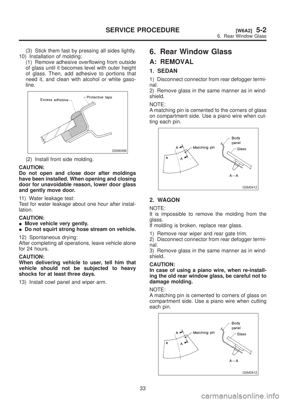
(3) Stick them fast by pressing all sides lightly.
10) Installation of molding:
(1) Remove adhesive overflowing from outside
of glass until it becomes level with outer height
of glass. Then, add adhesive to portions that
need it, and clean with alcohol or white gaso-
line.
G5M0496
(2) Install front side molding.
CAUTION:
Do not open and close door after moldings
have been installed. When opening and closing
door for unavoidable reason, lower door glass
and gently move door.
11) Water leakage test:
Test for water leakage about one hour after instal-
lation.
CAUTION:
IMove vehicle very gently.
IDo not squirt strong hose stream on vehicle.
12) Spontaneous drying:
After completing all operations, leave vehicle alone
for 24 hours.
CAUTION:
When delivering vehicle to user, tell him that
vehicle should not be subjected to heavy
shocks for at least three days.
13) Install cowl panel and wiper arm.
6. Rear Window Glass
A: REMOVAL
1. SEDAN
1) Disconnect connector from rear defogger termi-
nal.
2) Remove glass in the same manner as in wind-
shield.
NOTE:
A matching pin is cemented to the corners of glass
on compartment side. Use a piano wire when cut-
ting each pin.
G5M0412
2. WAGON
NOTE:
It is impossible to remove the molding from the
glass.
If molding is broken, replace rear glass.
1) Remove rear wiper and rear gate trim.
2) Disconnect connector from rear defogger termi-
nal.
3) Remove glass in the same manner as in wind-
shield.
CAUTION:
In case of using a piano wire, when re-install-
ing the old rear window glass, be careful not to
damage molding.
NOTE:
A matching pin is cemented to corners of glass on
compartment side. Use a piano wire when cutting
each pin.
G5M0412
33
[W6A2]5-2SERVICE PROCEDURE
6. Rear Window Glass
Page 1134 of 1456
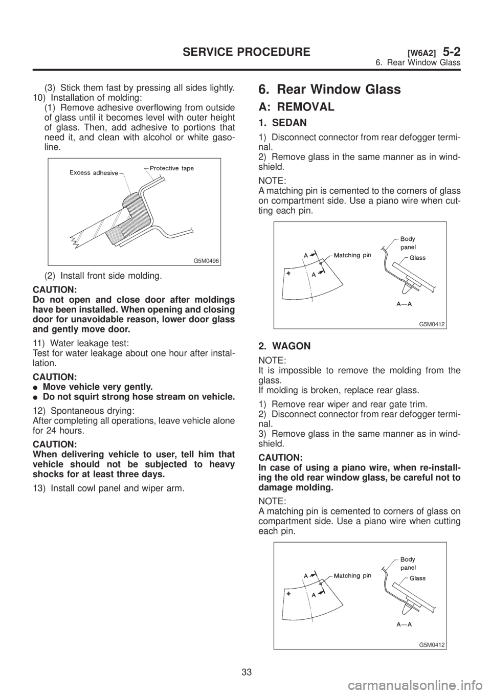
(3) Stick them fast by pressing all sides lightly.
10) Installation of molding:
(1) Remove adhesive overflowing from outside
of glass until it becomes level with outer height
of glass. Then, add adhesive to portions that
need it, and clean with alcohol or white gaso-
line.
G5M0496
(2) Install front side molding.
CAUTION:
Do not open and close door after moldings
have been installed. When opening and closing
door for unavoidable reason, lower door glass
and gently move door.
11) Water leakage test:
Test for water leakage about one hour after instal-
lation.
CAUTION:
IMove vehicle very gently.
IDo not squirt strong hose stream on vehicle.
12) Spontaneous drying:
After completing all operations, leave vehicle alone
for 24 hours.
CAUTION:
When delivering vehicle to user, tell him that
vehicle should not be subjected to heavy
shocks for at least three days.
13) Install cowl panel and wiper arm.
6. Rear Window Glass
A: REMOVAL
1. SEDAN
1) Disconnect connector from rear defogger termi-
nal.
2) Remove glass in the same manner as in wind-
shield.
NOTE:
A matching pin is cemented to the corners of glass
on compartment side. Use a piano wire when cut-
ting each pin.
G5M0412
2. WAGON
NOTE:
It is impossible to remove the molding from the
glass.
If molding is broken, replace rear glass.
1) Remove rear wiper and rear gate trim.
2) Disconnect connector from rear defogger termi-
nal.
3) Remove glass in the same manner as in wind-
shield.
CAUTION:
In case of using a piano wire, when re-install-
ing the old rear window glass, be careful not to
damage molding.
NOTE:
A matching pin is cemented to corners of glass on
compartment side. Use a piano wire when cutting
each pin.
G5M0412
33
[W6A2]5-2SERVICE PROCEDURE
6. Rear Window Glass
Page 1135 of 1456
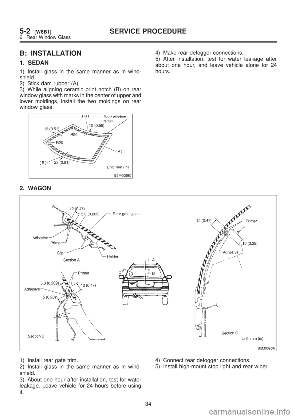
B: INSTALLATION
1. SEDAN
1) Install glass in the same manner as in wind-
shield.
2) Stick dam rubber (A).
3) While aligning ceramic print notch (B) on rear
window glass with marks in the center of upper and
lower moldings, install the two moldings on rear
window glass.
B5M0089C
4) Make rear defogger connections.
5) After installation, test for water leakage after
about one hour, and leave vehicle alone for 24
hours.
2. WAGON
B5M0090A
1) Install rear gate trim.
2) Install glass in the same manner as in wind-
shield.
3) About one hour after installation, test for water
leakage. Leave vehicle for 24 hours before using
it.4) Connect rear defogger connections.
5) Install high-mount stop light and rear wiper.
34
5-2[W6B1]SERVICE PROCEDURE
6. Rear Window Glass
Page 1226 of 1456
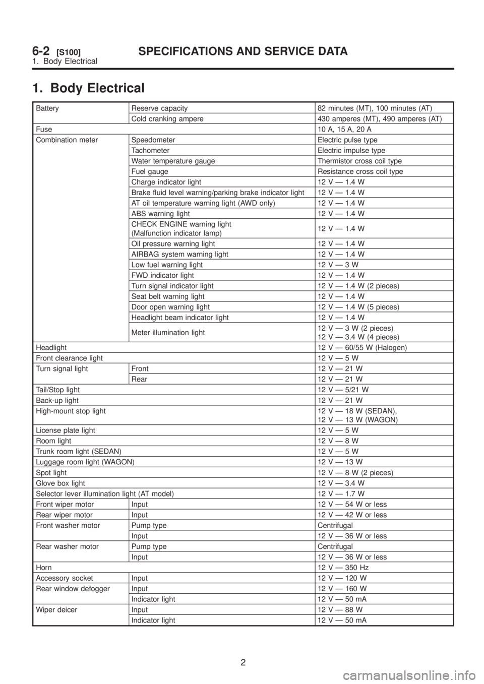
1. Body Electrical
Battery Reserve capacity 82 minutes (MT), 100 minutes (AT)
Cold cranking ampere 430 amperes (MT), 490 amperes (AT)
Fuse10 A, 15 A, 20 A
Combination meter Speedometer Electric pulse type
Tachometer Electric impulse type
Water temperature gauge Thermistor cross coil type
Fuel gauge Resistance cross coil type
Charge indicator light 12 V Ð 1.4 W
Brake fluid level warning/parking brake indicator light 12 V Ð 1.4 W
AT oil temperature warning light (AWD only) 12 V Ð 1.4 W
ABS warning light 12 V Ð 1.4 W
CHECK ENGINE warning light
(Malfunction indicator lamp)12 V Ð 1.4 W
Oil pressure warning light 12 V Ð 1.4 W
AIRBAG system warning light 12 V Ð 1.4 W
Low fuel warning light 12VÐ3W
FWD indicator light 12 V Ð 1.4 W
Turn signal indicator light 12 V Ð 1.4 W (2 pieces)
Seat belt warning light 12 V Ð 1.4 W
Door open warning light 12 V Ð 1.4 W (5 pieces)
Headlight beam indicator light 12 V Ð 1.4 W
Meter illumination light12VÐ3W(2pieces)
12 V Ð 3.4 W (4 pieces)
Headlight12 V Ð 60/55 W (Halogen)
Front clearance light 12VÐ5W
Turn signal light Front 12VÐ21W
Rear 12VÐ21W
Tail/Stop light12 V Ð 5/21 W
Back-up light12VÐ21W
High-mount stop light 12VÐ18W(SEDAN),
12VÐ13W(WAGON)
License plate light 12VÐ5W
Room light12VÐ8W
Trunk room light (SEDAN) 12VÐ5W
Luggage room light (WAGON) 12VÐ13W
Spot light12VÐ8W(2pieces)
Glove box light 12 V Ð 3.4 W
Selector lever illumination light (AT model) 12 V Ð 1.7 W
Front wiper motor Input 12VÐ54Worless
Rear wiper motor Input 12VÐ42Worless
Front washer motor Pump type Centrifugal
Input 12VÐ36Worless
Rear washer motor Pump type Centrifugal
Input 12VÐ36Worless
Horn12 V Ð 350 Hz
Accessory socket Input 12 V Ð 120 W
Rear window defogger Input 12 V Ð 160 W
Indicator light 12VÐ50mA
Wiper deicer Input 12VÐ88W
Indicator light 12VÐ50mA
2
6-2[S100]SPECIFICATIONS AND SERVICE DATA
1. Body Electrical
Page 1235 of 1456
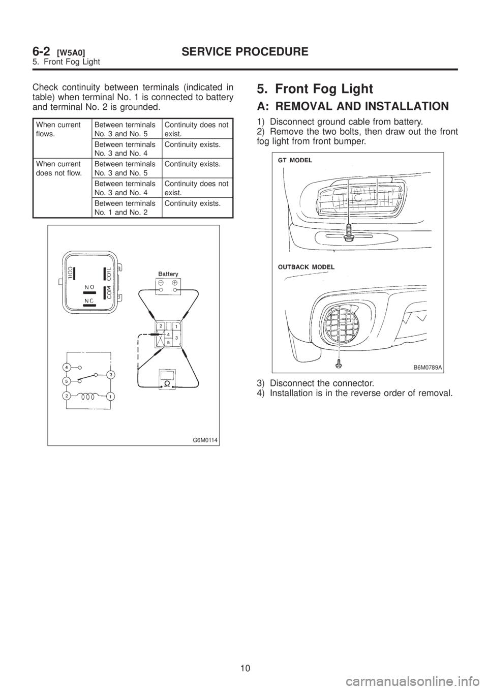
Check continuity between terminals (indicated in
table) when terminal No. 1 is connected to battery
and terminal No. 2 is grounded.
When current
flows.Between terminals
No. 3 and No. 5Continuity does not
exist.
Between terminals
No. 3 and No. 4Continuity exists.
When current
does not flow.Between terminals
No. 3 and No. 5Continuity exists.
Between terminals
No. 3 and No. 4Continuity does not
exist.
Between terminals
No. 1 and No. 2Continuity exists.
G6M0114
5. Front Fog Light
A: REMOVAL AND INSTALLATION
1) Disconnect ground cable from battery.
2) Remove the two bolts, then draw out the front
fog light from front bumper.
B6M0789A
3) Disconnect the connector.
4) Installation is in the reverse order of removal.
10
6-2[W5A0]SERVICE PROCEDURE
5. Front Fog Light
Page 1236 of 1456
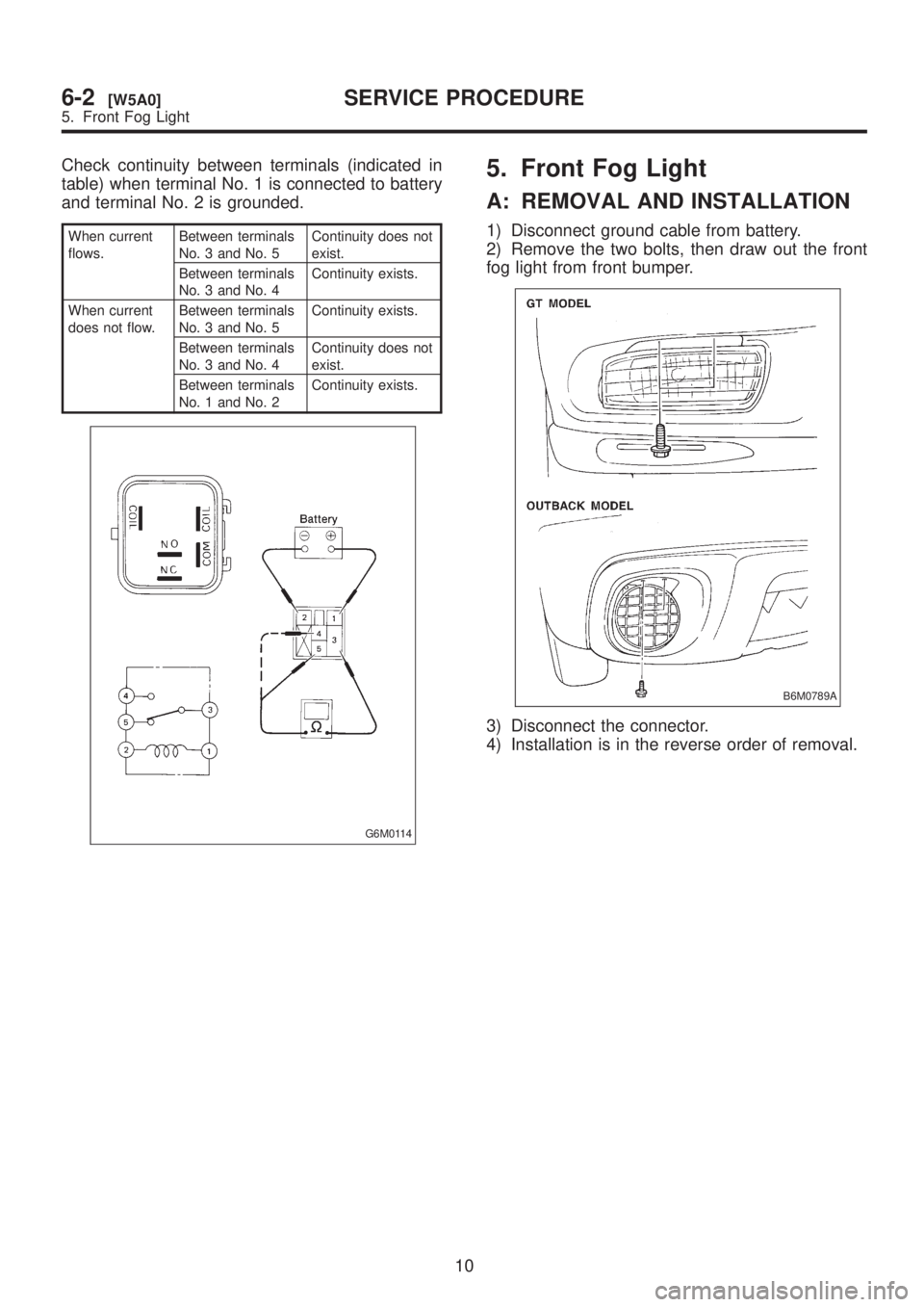
Check continuity between terminals (indicated in
table) when terminal No. 1 is connected to battery
and terminal No. 2 is grounded.
When current
flows.Between terminals
No. 3 and No. 5Continuity does not
exist.
Between terminals
No. 3 and No. 4Continuity exists.
When current
does not flow.Between terminals
No. 3 and No. 5Continuity exists.
Between terminals
No. 3 and No. 4Continuity does not
exist.
Between terminals
No. 1 and No. 2Continuity exists.
G6M0114
5. Front Fog Light
A: REMOVAL AND INSTALLATION
1) Disconnect ground cable from battery.
2) Remove the two bolts, then draw out the front
fog light from front bumper.
B6M0789A
3) Disconnect the connector.
4) Installation is in the reverse order of removal.
10
6-2[W5A0]SERVICE PROCEDURE
5. Front Fog Light
Page 1284 of 1456
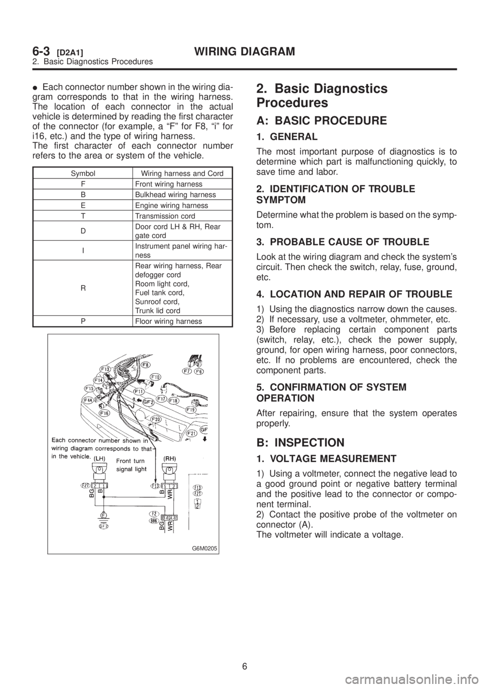
IEach connector number shown in the wiring dia-
gram corresponds to that in the wiring harness.
The location of each connector in the actual
vehicle is determined by reading the first character
of the connector (for example, a ªFº for F8, ªiº for
i16, etc.) and the type of wiring harness.
The first character of each connector number
refers to the area or system of the vehicle.
Symbol Wiring harness and Cord
F Front wiring harness
B Bulkhead wiring harness
E Engine wiring harness
T Transmission cord
DDoor cord LH & RH, Rear
gate cord
IInstrument panel wiring har-
ness
RRear wiring harness, Rear
defogger cord
Room light cord,
Fuel tank cord,
Sunroof cord,
Trunk lid cord
P Floor wiring harness
G6M0205
2. Basic Diagnostics
Procedures
A: BASIC PROCEDURE
1. GENERAL
The most important purpose of diagnostics is to
determine which part is malfunctioning quickly, to
save time and labor.
2. IDENTIFICATION OF TROUBLE
SYMPTOM
Determine what the problem is based on the symp-
tom.
3. PROBABLE CAUSE OF TROUBLE
Look at the wiring diagram and check the system's
circuit. Then check the switch, relay, fuse, ground,
etc.
4. LOCATION AND REPAIR OF TROUBLE
1) Using the diagnostics narrow down the causes.
2) If necessary, use a voltmeter, ohmmeter, etc.
3) Before replacing certain component parts
(switch, relay, etc.), check the power supply,
ground, for open wiring harness, poor connectors,
etc. If no problems are encountered, check the
component parts.
5. CONFIRMATION OF SYSTEM
OPERATION
After repairing, ensure that the system operates
properly.
B: INSPECTION
1. VOLTAGE MEASUREMENT
1) Using a voltmeter, connect the negative lead to
a good ground point or negative battery terminal
and the positive lead to the connector or compo-
nent terminal.
2) Contact the positive probe of the voltmeter on
connector (A).
The voltmeter will indicate a voltage.
6
6-3[D2A1]WIRING DIAGRAM
2. Basic Diagnostics Procedures