Page 10 of 1456
S6M0007A
4) Remove bolt which installs purge control sole-
noid valve to intake manifold.
S2M0055
5) Take out purge control solenoid valve.
6) Disconnect connector from purge control sole-
noid valve.
7) Disconnect vacuum hoses from purge control
solenoid valve.
S2M0056
8) Installation is in the reverse order of removal.
Tightening torque:
15.7
±1.5 N´m (1.6±0.15 kg-m, 11.6±1.1
ft-lb)
B2M2384A
B2M1201B
CAUTION:
Carefully connect the evaporation hoses.
B2M1893A
8
2-1[W4A0]SERVICE PROCEDURE
4. Purge Control Solenoid Valve
Page 11 of 1456
5. EGR Valve (2500 cc Model)
A: REMOVAL AND INSTALLATION
1) Remove air intake chamber.
B2M1679
2) Disconnect vacuum hose from EGR valve.
3) Remove bolts which install EGR valve onto
intake manifold.
B2M0423
4) Installation is in the reverse order of removal.
CAUTION:
Replace gasket with a new one.
Tightening torque:
18.6
±1.5 N´m (1.9±0.15 kg-m, 13.7±1.1
ft-lb)
6. Back-Pressure Transducer
(BPT) (2500 cc Model)
A: REMOVAL AND INSTALLATION
1) Disconnect vacuum hoses from BPT.
2) Remove BPT from bracket.
S2M0057
3) Installation is in the reverse order of removal.
9
[W6A0]2-1SERVICE PROCEDURE
6. Back-Pressure Transducer (BPT) (2500 cc Model)
Page 12 of 1456
5. EGR Valve (2500 cc Model)
A: REMOVAL AND INSTALLATION
1) Remove air intake chamber.
B2M1679
2) Disconnect vacuum hose from EGR valve.
3) Remove bolts which install EGR valve onto
intake manifold.
B2M0423
4) Installation is in the reverse order of removal.
CAUTION:
Replace gasket with a new one.
Tightening torque:
18.6
±1.5 N´m (1.9±0.15 kg-m, 13.7±1.1
ft-lb)
6. Back-Pressure Transducer
(BPT) (2500 cc Model)
A: REMOVAL AND INSTALLATION
1) Disconnect vacuum hoses from BPT.
2) Remove BPT from bracket.
S2M0057
3) Installation is in the reverse order of removal.
9
[W6A0]2-1SERVICE PROCEDURE
6. Back-Pressure Transducer (BPT) (2500 cc Model)
Page 13 of 1456
7. EGR Solenoid Valve (2500 cc
Model)
A: REMOVAL AND INSTALLATION
1) Disconnect battery ground cable.
B2M1723
2) Remove air intake chamber.
[W18A0].>
B2M1679
3) Disconnect vacuum hoses from EGR solenoid
valve.
4) Disconnect connector from EGR solenoid
valve.
S2M0058A
5) Remove bolt which installs EGR solenoid valve
onto intake manifold.
S2M0059
6) Installation is in the reverse order of removal.
Tightening torque:
15.7
±1.5 N´m (1.6±0.15 kg-m, 11.6±1.1
ft-lb)
10
2-1[W7A0]SERVICE PROCEDURE
7. EGR Solenoid Valve (2500 cc Model)
Page 18 of 1456
10. Pressure Control Solenoid
Valve
A: REMOVAL AND INSTALLATION
1) Disconnect battery ground cable.
B2M1723
2) Remove canister.
B2M1780
3) Remove bolt which installs pressure control
solenoid valve holding bracket on body.
B2M1781
4) Disconnect connector from pressure control
solenoid valve.
B2M1782
5) Disconnect two evaporation hoses from pres-
sure control solenoid valve.
6) Remove pressure control solenoid valve with
bracket.
B2M1783
7) Remove pressure control solenoid valve from
bracket.
B2M1786
8) Disconnect vacuum hose from pressure control
solenoid valve.
B2M1785
14
2-1[W10A0]SERVICE PROCEDURE
10. Pressure Control Solenoid Valve
Page 21 of 1456
5) Disconnect connector from vent control sole-
noid valve.
B2M0964
6) Remove one bolt fixing bracket on the body.
H2M1469
7) Remove two vacuum hoses from vent control
solenoid valve.
B2M0965A
8) Remove one bolt fixing vent control solenoid
valve on bracket.
B2M0966
9) Remove vent control solenoid valve.
B: INSTALLATION
1) Install the bolt fixing vent control solenoid valve
on bracket.
B2M0966
2) Install two vacuum hoses to vent control sole-
noid valve.
B2M0965A
3) Install the bolt fixing bracket on the body.
Tightening torque:
25
±7 N´m (2.5±0.7 kg-m, 18.1±5.1 ft-lb)
H2M1469
16
2-1[W11B0]SERVICE PROCEDURE
11. Vent Control Solenoid Valve (2500 cc Model)
Page 38 of 1456

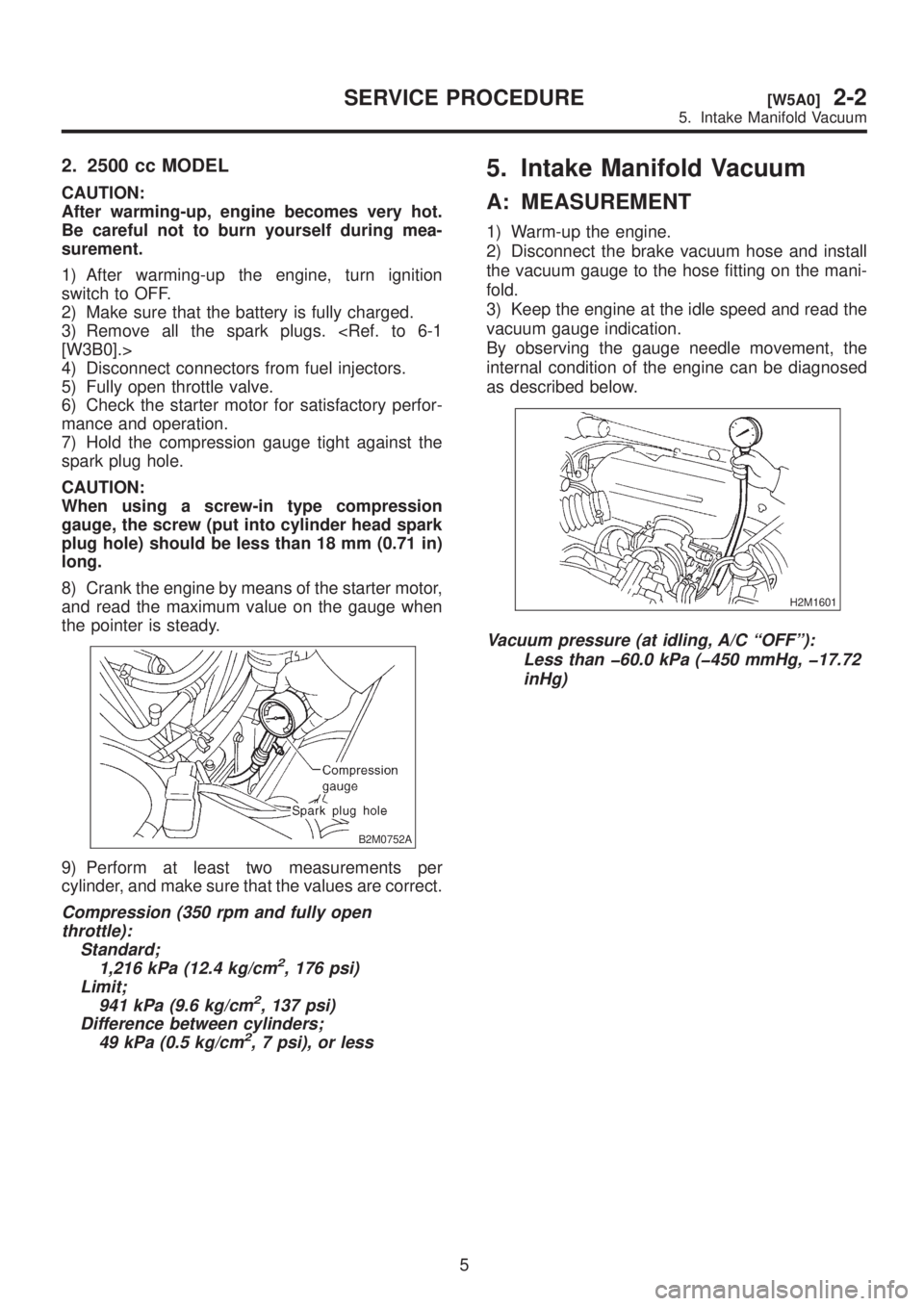
2. 2500 cc MODEL
CAUTION:
After warming-up, engine becomes very hot.
Be careful not to burn yourself during mea-
surement.
1) After warming-up the engine, turn ignition
switch to OFF.
2) Make sure that the battery is fully charged.
3) Remove all the spark plugs.
[W3B0].>
4) Disconnect connectors from fuel injectors.
5) Fully open throttle valve.
6) Check the starter motor for satisfactory perfor-
mance and operation.
7) Hold the compression gauge tight against the
spark plug hole.
CAUTION:
When using a screw-in type compression
gauge, the screw (put into cylinder head spark
plug hole) should be less than 18 mm (0.71 in)
long.
8) Crank the engine by means of the starter motor,
and read the maximum value on the gauge when
the pointer is steady.
B2M0752A
9) Perform at least two measurements per
cylinder, and make sure that the values are correct.
Compression (350 rpm and fully open
throttle):
Standard;
1,216 kPa (12.4 kg/cm
2, 176 psi)
Limit;
941 kPa (9.6 kg/cm
2, 137 psi)
Difference between cylinders;
49 kPa (0.5 kg/cm
2, 7 psi), or less
5. Intake Manifold Vacuum
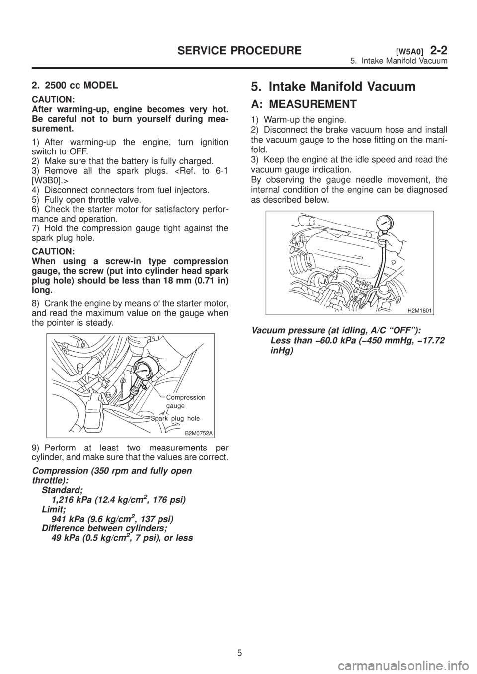
A: MEASUREMENT
1) Warm-up the engine.
2) Disconnect the brake vacuum hose and install
the vacuum gauge to the hose fitting on the mani-
fold.
3) Keep the engine at the idle speed and read the
vacuum gauge indication.
By observing the gauge needle movement, the
internal condition of the engine can be diagnosed
as described below.
H2M1601
Vacuum pressure (at idling, A/C ªOFFº):
Less than þ60.0 kPa (þ450 mmHg, þ17.72
inHg)
5
[W5A0]2-2SERVICE PROCEDURE
5. Intake Manifold Vacuum
Page 39 of 1456

2. 2500 cc MODEL
CAUTION:
After warming-up, engine becomes very hot.
Be careful not to burn yourself during mea-
surement.
1) After warming-up the engine, turn ignition
switch to OFF.
2) Make sure that the battery is fully charged.
3) Remove all the spark plugs.
[W3B0].>
4) Disconnect connectors from fuel injectors.
5) Fully open throttle valve.
6) Check the starter motor for satisfactory perfor-
mance and operation.
7) Hold the compression gauge tight against the
spark plug hole.
CAUTION:
When using a screw-in type compression
gauge, the screw (put into cylinder head spark
plug hole) should be less than 18 mm (0.71 in)
long.
8) Crank the engine by means of the starter motor,
and read the maximum value on the gauge when
the pointer is steady.
B2M0752A
9) Perform at least two measurements per
cylinder, and make sure that the values are correct.
Compression (350 rpm and fully open
throttle):
Standard;
1,216 kPa (12.4 kg/cm
2, 176 psi)
Limit;
941 kPa (9.6 kg/cm
2, 137 psi)
Difference between cylinders;
49 kPa (0.5 kg/cm
2, 7 psi), or less
5. Intake Manifold Vacuum
A: MEASUREMENT
1) Warm-up the engine.
2) Disconnect the brake vacuum hose and install
the vacuum gauge to the hose fitting on the mani-
fold.
3) Keep the engine at the idle speed and read the
vacuum gauge indication.
By observing the gauge needle movement, the
internal condition of the engine can be diagnosed
as described below.
H2M1601
Vacuum pressure (at idling, A/C ªOFFº):
Less than þ60.0 kPa (þ450 mmHg, þ17.72
inHg)
5
[W5A0]2-2SERVICE PROCEDURE
5. Intake Manifold Vacuum