1999 SUBARU LEGACY change wheel
[x] Cancel search: change wheelPage 711 of 1456

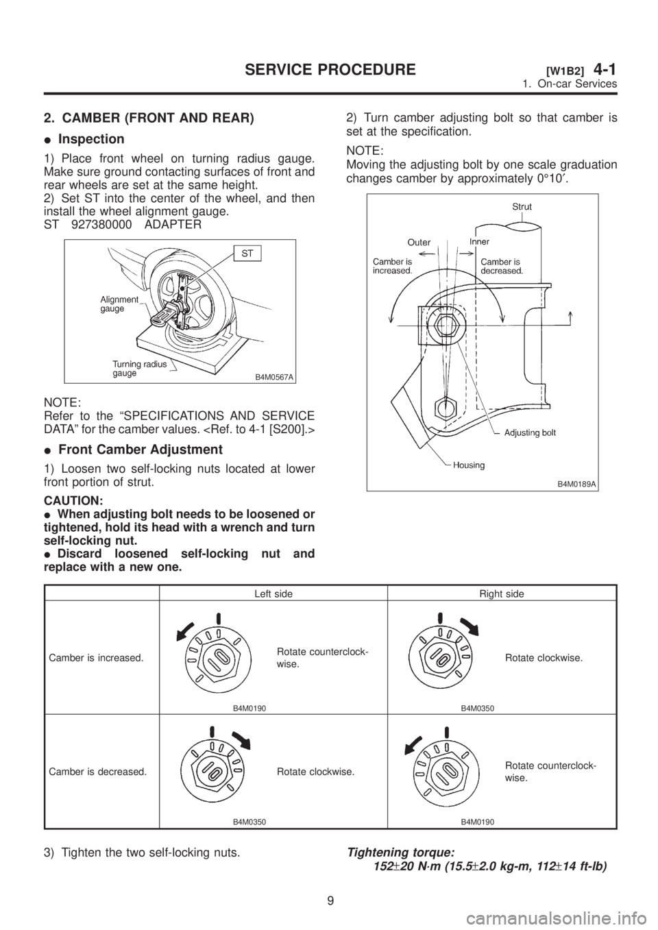
2. CAMBER (FRONT AND REAR)
IInspection
1) Place front wheel on turning radius gauge.
Make sure ground contacting surfaces of front and
rear wheels are set at the same height.
2) Set ST into the center of the wheel, and then
install the wheel alignment gauge.
ST 927380000 ADAPTER
B4M0567A
NOTE:
Refer to the ªSPECIFICATIONS AND SERVICE
DATAº for the camber values.
IFront Camber Adjustment
1) Loosen two self-locking nuts located at lower
front portion of strut.
CAUTION:
IWhen adjusting bolt needs to be loosened or
tightened, hold its head with a wrench and turn
self-locking nut.
IDiscard loosened self-locking nut and
replace with a new one.2) Turn camber adjusting bolt so that camber is
set at the specification.
NOTE:
Moving the adjusting bolt by one scale graduation
changes camber by approximately 0É10¢.
B4M0189A
Left side Right side
Camber is increased.
B4M0190
Rotate counterclock-
wise.
B4M0350
Rotate clockwise.
Camber is decreased.
B4M0350
Rotate clockwise.
B4M0190
Rotate counterclock-
wise.
3) Tighten the two self-locking nuts.Tightening torque:
152
±20 N´m (15.5±2.0 kg-m, 112±14 ft-lb)
9
[W1B2]4-1SERVICE PROCEDURE
1. On-car Services
Page 713 of 1456

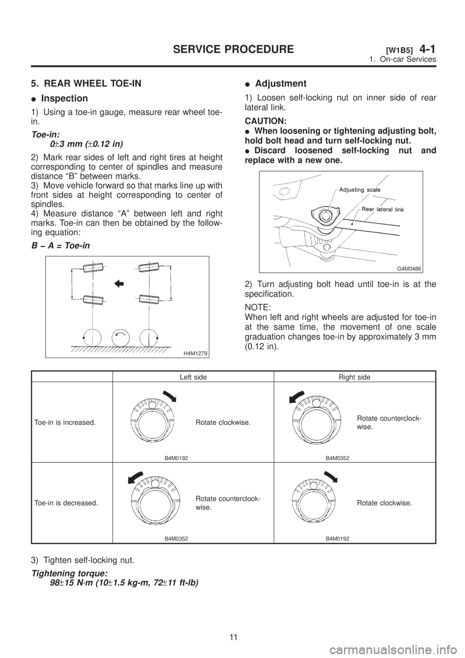
5. REAR WHEEL TOE-IN
IInspection
1) Using a toe-in gauge, measure rear wheel toe-
in.
Toe-in:
0
±3mm(±0.12 in)
2) Mark rear sides of left and right tires at height
corresponding to center of spindles and measure
distance ªBº between marks.
3) Move vehicle forward so that marks line up with
front sides at height corresponding to center of
spindles.
4) Measure distance ªAº between left and right
marks. Toe-in can then be obtained by the follow-
ing equation:
B þ A = Toe-in
H4M1279
IAdjustment
1) Loosen self-locking nut on inner side of rear
lateral link.
CAUTION:
IWhen loosening or tightening adjusting bolt,
hold bolt head and turn self-locking nut.
IDiscard loosened self-locking nut and
replace with a new one.
G4M0486
2) Turn adjusting bolt head until toe-in is at the
specification.
NOTE:
When left and right wheels are adjusted for toe-in
at the same time, the movement of one scale
graduation changes toe-in by approximately 3 mm
(0.12 in).
Left side Right side
Toe-in is increased.
B4M0192
Rotate clockwise.
B4M0352
Rotate counterclock-
wise.
Toe-in is decreased.
B4M0352
Rotate counterclock-
wise.
B4M0192
Rotate clockwise.
3) Tighten self-locking nut.
Tightening torque:
98
±15 N´m (10±1.5 kg-m, 72±11 ft-lb)
11
[W1B5]4-1SERVICE PROCEDURE
1. On-car Services
Page 714 of 1456

6. THRUST ANGLE
IInspection
1) Position vehicle on a level surface.
2) Move vehicle 3 to 4 meters directly forward.
3) Determine locus of both front and rear axles.
4) Measure distance ªLº between center line of
loci of the axles.
Thrust angle:
Less than 20
¢when ªLº is equal to or
less than 15 mm (0.59 in).
G4M0488
IAdjustment
1) Make thrust angle adjustments by turning toe-in
adjusting bolts of rear suspension equally in the
same direction.
2) When one rear wheel is adjusted in a toe-in
direction, adjust the other rear wheel equally in
toe-out direction, in order to make thrust angle
adjustment.
3) When left and right adjusting bolts are turned
incrementally by one graduation in the same
direction, the thrust angle will change approxi-
mately 10' [ªLº is almost equal to 7.5 mm (0.295
in)].
Thrust angle:
0É
±20¢
G4M0488
12
4-1[W1B6]SERVICE PROCEDURE
1. On-car Services
Page 860 of 1456

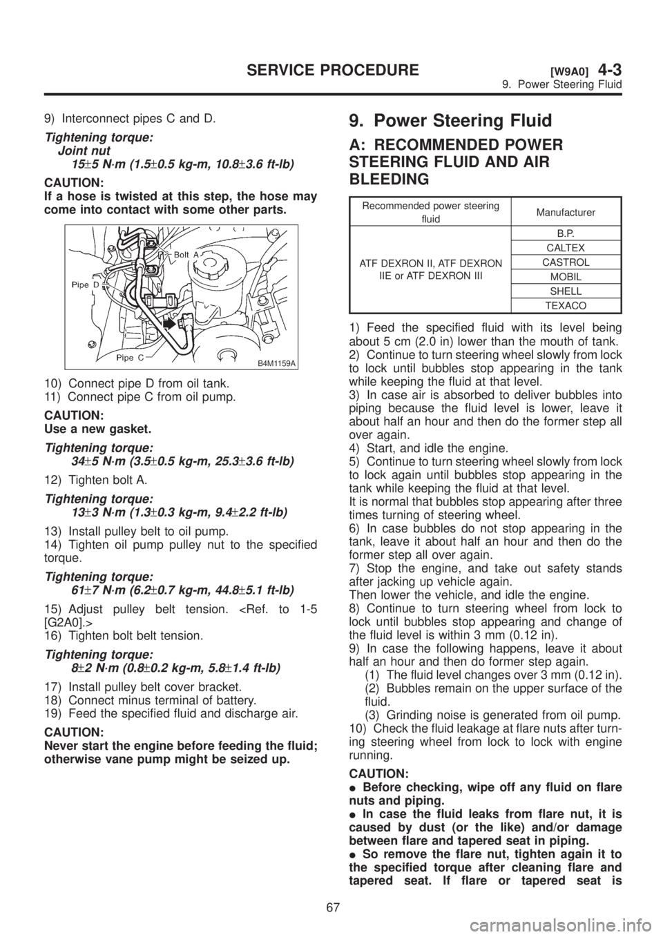
9) Interconnect pipes C and D.
Tightening torque:
Joint nut
15
±5 N´m (1.5±0.5 kg-m, 10.8±3.6 ft-lb)
CAUTION:
If a hose is twisted at this step, the hose may
come into contact with some other parts.
B4M1159A
10) Connect pipe D from oil tank.
11) Connect pipe C from oil pump.
CAUTION:
Use a new gasket.
Tightening torque:
34
±5 N´m (3.5±0.5 kg-m, 25.3±3.6 ft-lb)
12) Tighten bolt A.
Tightening torque:
13
±3 N´m (1.3±0.3 kg-m, 9.4±2.2 ft-lb)
13) Install pulley belt to oil pump.
14) Tighten oil pump pulley nut to the specified
torque.
Tightening torque:
61
±7 N´m (6.2±0.7 kg-m, 44.8±5.1 ft-lb)
15) Adjust pulley belt tension.
16) Tighten bolt belt tension.
Tightening torque:
8
±2 N´m (0.8±0.2 kg-m, 5.8±1.4 ft-lb)
17) Install pulley belt cover bracket.
18) Connect minus terminal of battery.
19) Feed the specified fluid and discharge air.
CAUTION:
Never start the engine before feeding the fluid;
otherwise vane pump might be seized up.
9. Power Steering Fluid
A: RECOMMENDED POWER
STEERING FLUID AND AIR
BLEEDING
Recommended power steering
fluidManufacturer
ATF DEXRON II, ATF DEXRON
IIE or ATF DEXRON IIIB.P.
CALTEX
CASTROL
MOBIL
SHELL
TEXACO
1) Feed the specified fluid with its level being
about 5 cm (2.0 in) lower than the mouth of tank.
2) Continue to turn steering wheel slowly from lock
to lock until bubbles stop appearing in the tank
while keeping the fluid at that level.
3) In case air is absorbed to deliver bubbles into
piping because the fluid level is lower, leave it
about half an hour and then do the former step all
over again.
4) Start, and idle the engine.
5) Continue to turn steering wheel slowly from lock
to lock again until bubbles stop appearing in the
tank while keeping the fluid at that level.
It is normal that bubbles stop appearing after three
times turning of steering wheel.
6) In case bubbles do not stop appearing in the
tank, leave it about half an hour and then do the
former step all over again.
7) Stop the engine, and take out safety stands
after jacking up vehicle again.
Then lower the vehicle, and idle the engine.
8) Continue to turn steering wheel from lock to
lock until bubbles stop appearing and change of
the fluid level is within 3 mm (0.12 in).
9) In case the following happens, leave it about
half an hour and then do former step again.
(1) The fluid level changes over 3 mm (0.12 in).
(2) Bubbles remain on the upper surface of the
fluid.
(3) Grinding noise is generated from oil pump.
10) Check the fluid leakage at flare nuts after turn-
ing steering wheel from lock to lock with engine
running.
CAUTION:
IBefore checking, wipe off any fluid on flare
nuts and piping.
IIn case the fluid leaks from flare nut, it is
caused by dust (or the like) and/or damage
between flare and tapered seat in piping.
ISo remove the flare nut, tighten again it to
the specified torque after cleaning flare and
tapered seat. If flare or tapered seat is
67
[W9A0]4-3SERVICE PROCEDURE
9. Power Steering Fluid
Page 861 of 1456

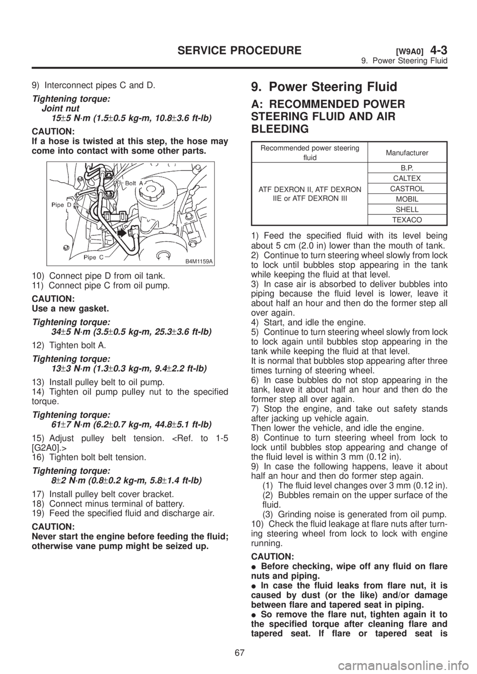
9) Interconnect pipes C and D.
Tightening torque:
Joint nut
15
±5 N´m (1.5±0.5 kg-m, 10.8±3.6 ft-lb)
CAUTION:
If a hose is twisted at this step, the hose may
come into contact with some other parts.
B4M1159A
10) Connect pipe D from oil tank.
11) Connect pipe C from oil pump.
CAUTION:
Use a new gasket.
Tightening torque:
34
±5 N´m (3.5±0.5 kg-m, 25.3±3.6 ft-lb)
12) Tighten bolt A.
Tightening torque:
13
±3 N´m (1.3±0.3 kg-m, 9.4±2.2 ft-lb)
13) Install pulley belt to oil pump.
14) Tighten oil pump pulley nut to the specified
torque.
Tightening torque:
61
±7 N´m (6.2±0.7 kg-m, 44.8±5.1 ft-lb)
15) Adjust pulley belt tension.
16) Tighten bolt belt tension.
Tightening torque:
8
±2 N´m (0.8±0.2 kg-m, 5.8±1.4 ft-lb)
17) Install pulley belt cover bracket.
18) Connect minus terminal of battery.
19) Feed the specified fluid and discharge air.
CAUTION:
Never start the engine before feeding the fluid;
otherwise vane pump might be seized up.
9. Power Steering Fluid
A: RECOMMENDED POWER
STEERING FLUID AND AIR
BLEEDING
Recommended power steering
fluidManufacturer
ATF DEXRON II, ATF DEXRON
IIE or ATF DEXRON IIIB.P.
CALTEX
CASTROL
MOBIL
SHELL
TEXACO
1) Feed the specified fluid with its level being
about 5 cm (2.0 in) lower than the mouth of tank.
2) Continue to turn steering wheel slowly from lock
to lock until bubbles stop appearing in the tank
while keeping the fluid at that level.
3) In case air is absorbed to deliver bubbles into
piping because the fluid level is lower, leave it
about half an hour and then do the former step all
over again.
4) Start, and idle the engine.
5) Continue to turn steering wheel slowly from lock
to lock again until bubbles stop appearing in the
tank while keeping the fluid at that level.
It is normal that bubbles stop appearing after three
times turning of steering wheel.
6) In case bubbles do not stop appearing in the
tank, leave it about half an hour and then do the
former step all over again.
7) Stop the engine, and take out safety stands
after jacking up vehicle again.
Then lower the vehicle, and idle the engine.
8) Continue to turn steering wheel from lock to
lock until bubbles stop appearing and change of
the fluid level is within 3 mm (0.12 in).
9) In case the following happens, leave it about
half an hour and then do former step again.
(1) The fluid level changes over 3 mm (0.12 in).
(2) Bubbles remain on the upper surface of the
fluid.
(3) Grinding noise is generated from oil pump.
10) Check the fluid leakage at flare nuts after turn-
ing steering wheel from lock to lock with engine
running.
CAUTION:
IBefore checking, wipe off any fluid on flare
nuts and piping.
IIn case the fluid leaks from flare nut, it is
caused by dust (or the like) and/or damage
between flare and tapered seat in piping.
ISo remove the flare nut, tighten again it to
the specified torque after cleaning flare and
tapered seat. If flare or tapered seat is
67
[W9A0]4-3SERVICE PROCEDURE
9. Power Steering Fluid