Page 63 of 1456
5. Crankshaft and Piston
B2M1958A
(1) Flywheel (MT)
(2) Bell bearing (MT)
(3) Reinforcement (AT)
(4) Drive plate (AT)
(5) Top ring
(6) Second ring
(7) Oil ring
(8) Piston(9) Piston pin
(10) Circlip
(11) Connecting rod bolt
(12) Connecting rod
(13) Connecting rod bearing
(14) Connecting rod cap
(15) Crankshaft
(16) Woodruff key(17) Crankshaft bearing #1, #3
(18) Crankshaft bearing #2, #4
(19) Crankshaft bearing #5
Tightening torque: N´m (kg-m, ft-lb)
T1:
44±2 (4.5±0.2, 32.5±1.4)
T2:72±3 (7.3±0.3, 52.8±2.2)
10
2-3a[C500]COMPONENT PARTS
5. Crankshaft and Piston
Page 65 of 1456
1. General Precautions
A: GENERAL PRECAUTIONS
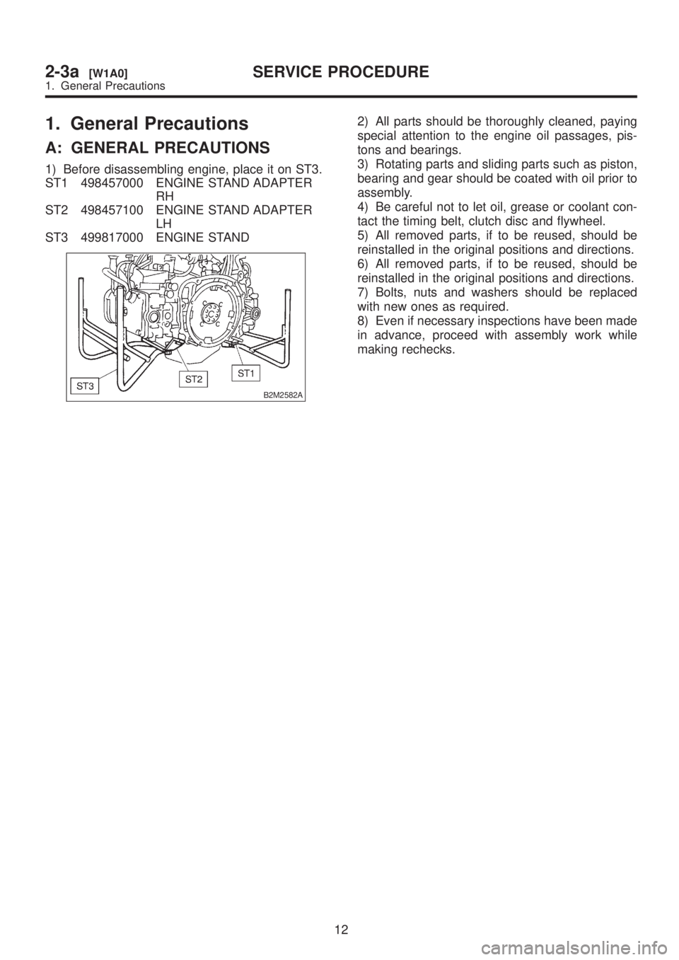
1) Before disassembling engine, place it on ST3.
ST1 498457000 ENGINE STAND ADAPTER
RH
ST2 498457100 ENGINE STAND ADAPTER
LH
ST3 499817000 ENGINE STAND
B2M2582A
2) All parts should be thoroughly cleaned, paying
special attention to the engine oil passages, pis-
tons and bearings.
3) Rotating parts and sliding parts such as piston,
bearing and gear should be coated with oil prior to
assembly.
4) Be careful not to let oil, grease or coolant con-
tact the timing belt, clutch disc and flywheel.
5) All removed parts, if to be reused, should be
reinstalled in the original positions and directions.
6) All removed parts, if to be reused, should be
reinstalled in the original positions and directions.
7) Bolts, nuts and washers should be replaced
with new ones as required.
8) Even if necessary inspections have been made
in advance, proceed with assembly work while
making rechecks.
12
2-3a[W1A0]SERVICE PROCEDURE
1. General Precautions
Page 132 of 1456

2. Engine Noise
Type of sound Condition Possible cause
Regular clicking soundSound increases as engine
speed increases.IValve mechanism is defective.
IIncorrect valve clearance
IWorn valve rocker
IWorn camshaft
IBroken valve spring
Heavy and dull clankOil pressure is low.IWorn crankshaft main bearing
IWorn connecting rod bearing (big end)
Oil pressure is normal.ILoose flywheel mounting bolts
IDamaged engine mounting
High-pitched clank
(Spark knock)Sound is noticeable when
accelerating with an overload.IIgnition timing advanced
IAccumulation of carbon inside combustion chamber
IWrong spark plug
IImproper gasoline
Clank when engine speed is
medium (1,000 to 2,000 rpm)Sound is reduced when fuel
injector connector of noisy cyl-
inder is disconnected.
(NOTE*)IWorn crankshaft main bearing
IWorn bearing at crankshaft end of connecting rod
Knocking sound when engine
is operating under idling speed
and engine is warmSound is reduced when fuel
injector connector of noisy cyl-
inder is disconnected.
(NOTE*)IWorn cylinder liner and piston ring
IBroken or stuck piston ring
IWorn piston pin and hole at piston end of connecting rod
Sound is not reduced if each
fuel injector connector is dis-
connected in turn. (NOTE*)IUnusually worn valve lifter
IWorn cam gear
IWorn camshaft journal bore in crankcase
Squeaky sound ÐIInsufficient generator lubrication
Rubbing sound ÐIDefective generator brush and rotor contact
Gear scream when starting
engineÐIDefective ignition starter switch
IWorn gear and starter pinion
Sound like polishing glass with
a dry clothÐILoose drive belt
IDefective engine coolant pump shaft
Hissing sound ÐILoss of compression
IAir leakage in air intake system, hoses, connections or
manifolds
Timing belt noise ÐILoose timing belt
IBelt contacting case/adjacent part
Valve tappet noise ÐIIncorrect valve clearance
NOTE*:
When disconnecting fuel injector connector, Malfunction Indicator Light (CHECK ENGINE light) illuminates and trouble code is
stored in ECM memory.
Therefore, carry out the CLEAR MEMORY MODE and INSPECTION MODE after con-
necting fuel injector connector.
78
2-3a[K200]DIAGNOSTICS
2. Engine Noise
Page 143 of 1456
5. Crankshaft and Piston
B2M1958A
(1) Flywheel (MT vehicles only)
(2) Bell bearing (MT vehicles only)
(3) Reinforcement (AT vehicles only)
(4) Drive plate (AT vehicles only)
(5) Top ring
(6) Second ring
(7) Oil ring
(8) Piston(9) Piston pin
(10) Circlip
(11) Connecting rod bolt
(12) Connecting rod
(13) Connecting rod bearing
(14) Connecting rod cap
(15) Crankshaft
(16) Woodruff key(17) Crankshaft bearing #1, #3
(18) Crankshaft bearing #2, #4
(19) Crankshaft bearing #5
Tightening torque: N´m (kg-m, ft-lb)
T1:
44±2 (4.5±0.2, 32.5±1.4)
T2:72±3 (7.3±0.3, 52.8±2.2)
12
2-3b[C500]COMPONENT PARTS
5. Crankshaft and Piston
Page 144 of 1456
1. Precautions
A: GENERAL PRECAUTIONS
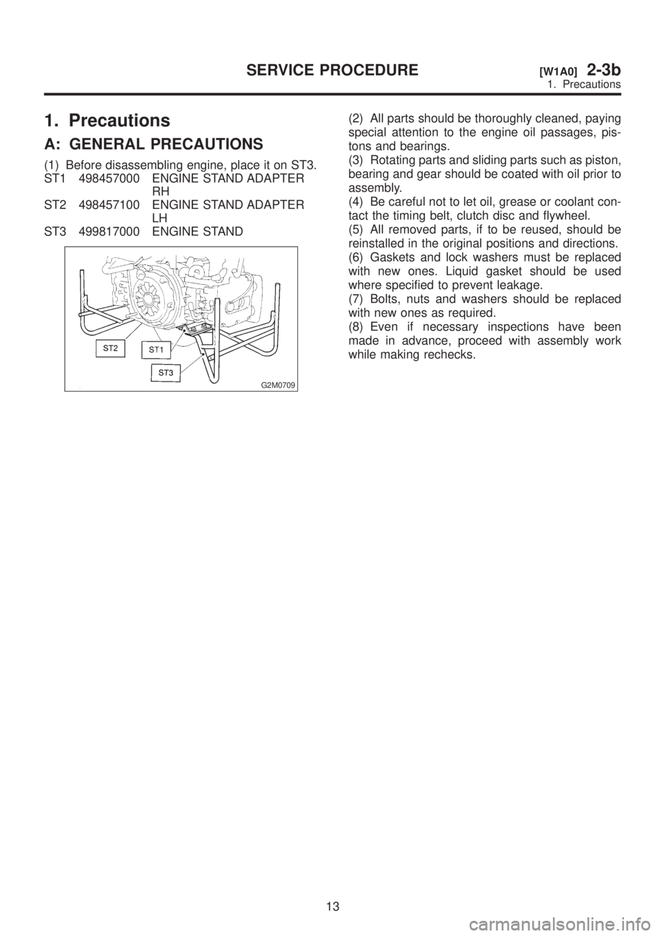
(1) Before disassembling engine, place it on ST3.
ST1 498457000 ENGINE STAND ADAPTER
RH
ST2 498457100 ENGINE STAND ADAPTER
LH
ST3 499817000 ENGINE STAND
G2M0709
(2) All parts should be thoroughly cleaned, paying
special attention to the engine oil passages, pis-
tons and bearings.
(3) Rotating parts and sliding parts such as piston,
bearing and gear should be coated with oil prior to
assembly.
(4) Be careful not to let oil, grease or coolant con-
tact the timing belt, clutch disc and flywheel.
(5) All removed parts, if to be reused, should be
reinstalled in the original positions and directions.
(6) Gaskets and lock washers must be replaced
with new ones. Liquid gasket should be used
where specified to prevent leakage.
(7) Bolts, nuts and washers should be replaced
with new ones as required.
(8) Even if necessary inspections have been
made in advance, proceed with assembly work
while making rechecks.
13
[W1A0]2-3bSERVICE PROCEDURE
1. Precautions
Page 207 of 1456
2. Engine Noise
If noise still exists, conduct diagnostics procedures
in accordance with the following table.CAUTION:
Do not disconnect spark plug cord while
engine is running.
Type of sound Condition Possible cause
Regular clicking soundSound increases as engine
speed increases.Valve mechanism is defective.
IIncorrect valve clearance
IWorn camshaft
IBroken valve spring
Heavy and dull clankOil pressure is low.IWorn crankshaft main bearing
IWorn connecting rod bearing (big end)
Oil pressure is normal.ILoose flywheel mounting bolts
IDamaged engine mounting
High-pitched clank
(Spark knock)Sound is noticeable when
accelerating with an overload.IIgnition timing advanced
IAccumulation of carbon inside combustion chamber
IWrong spark plug
IImproper gasoline
Clank when engine speed is
medium (1,000 to 2,000 rpm).Sound is reduced when fuel
injector connector of noisy cyl-
inder is disconnected.
(NOTE*)IWorn crankshaft main bearing
IWorn bearing at crankshaft end of connecting rod
Knocking sound when engine
is operating under idling speed
and engine is warm.Sound is reduced when fuel
injector connector of noisy cyl-
inder is disconnected.
(NOTE*)IWorn cylinder liner and piston ring
IBroken or stuck piston ring
IWorn piston pin and hole at piston end of connecting rod
Sound is not reduced if each
fuel injector connector is dis-
connected in turn.
(NOTE*)IUnusually worn valve lifter
IWorn camshaft journal bore in crankcase
Squeaky sound ÐIInsufficient generator lubrication
Rubbing sound ÐIDefective generator brush and rotor contact
Gear scream when starting
engineÐIDefective ignition starter switch
IWorn gear and starter pinion
Sound like polishing glass with
a dry clothÐILoose drive belt
IDefective engine coolant pump shaft
Hissing sound ÐILoss of compression
IAir leakage in air intake system, hoses, connections or
manifolds
Timing belt noise ÐILoose timing belt
IBelt contacting case/adjacent part
Valve tappet noise ÐIIncorrect valve clearance
NOTE*:
When disconnecting fuel injector connector, Malfunction Indicator Light (CHECK ENGINE light) illuminates and trouble code is
stored in ECM memory.
Therefore, carry out the CLEAR MEMORY MODE and INSPECTION MODE after connecting fuel injector connector.
[T6A0].>
76
2-3b[K200]DIAGNOSTICS
2. Engine Noise
Page 413 of 1456
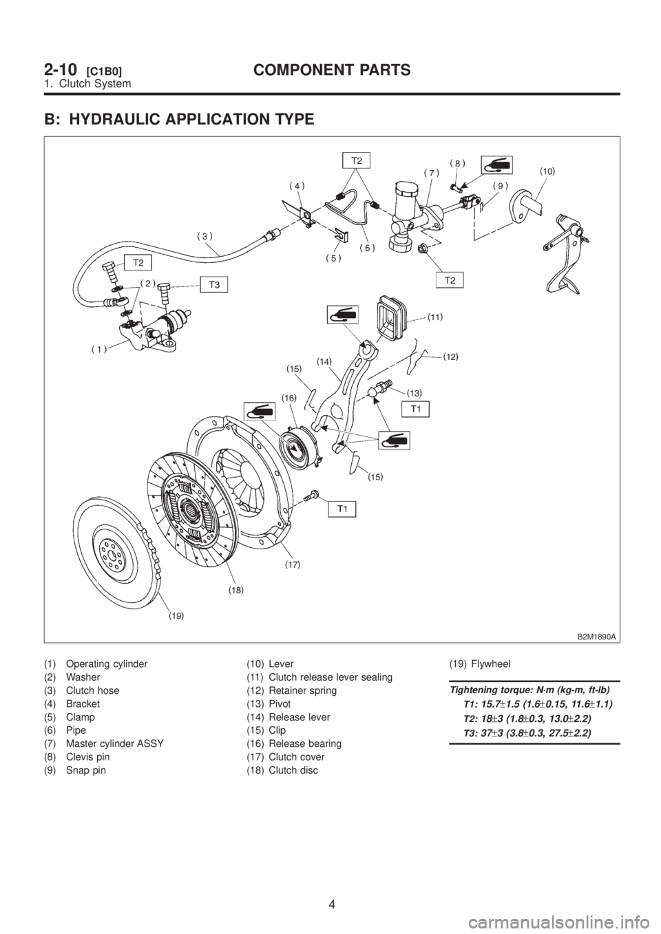
B: HYDRAULIC APPLICATION TYPE
B2M1890A
(1) Operating cylinder
(2) Washer
(3) Clutch hose
(4) Bracket
(5) Clamp
(6) Pipe
(7) Master cylinder ASSY
(8) Clevis pin
(9) Snap pin(10) Lever
(11) Clutch release lever sealing
(12) Retainer spring
(13) Pivot
(14) Release lever
(15) Clip
(16) Release bearing
(17) Clutch cover
(18) Clutch disc(19) Flywheel
Tightening torque: N´m (kg-m, ft-lb)
T1:
15.7±1.5 (1.6±0.15, 11.6±1.1)
T2:18±3 (1.8±0.3, 13.0±2.2)
T3:37±3 (3.8±0.3, 27.5±2.2)
4
2-10[C1B0]COMPONENT PARTS
1. Clutch System
Page 421 of 1456
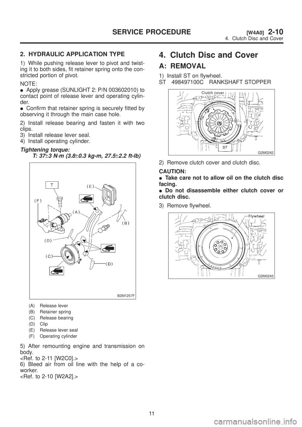
2. HYDRAULIC APPLICATION TYPE
1) While pushing release lever to pivot and twist-
ing it to both sides, fit retainer spring onto the con-
stricted portion of pivot.
NOTE:
IApply grease (SUNLIGHT 2: P/N 003602010) to
contact point of release lever and operating cylin-
der.
IConfirm that retainer spring is securely fitted by
observing it through the main case hole.
2) Install release bearing and fasten it with two
clips.
3) Install release lever seal.
4) Install operating cylinder.
Tightening torque:
T: 3 7
±3 N´m (3.8±0.3 kg-m, 27.5±2.2 ft-lb)
B2M1257F
(A) Release lever
(B) Retainer spring
(C) Release bearing
(D) Clip
(E) Release lever seal
(F) Operating cylinder
5) After remounting engine and transmission on
body.
6) Bleed air from oil line with the help of a co-
worker.
4. Clutch Disc and Cover
A: REMOVAL
1) Install ST on flywheel.
ST 498497100C RANKSHAFT STOPPER
G2M0242
2) Remove clutch cover and clutch disc.
CAUTION:
ITake care not to allow oil on the clutch disc
facing.
IDo not disassemble either clutch cover or
clutch disc.
3) Remove flywheel.
G2M0243
11
[W4A0]2-10SERVICE PROCEDURE
4. Clutch Disc and Cover