1999 SUBARU LEGACY warning light
[x] Cancel search: warning lightPage 42 of 1456
S2M0242
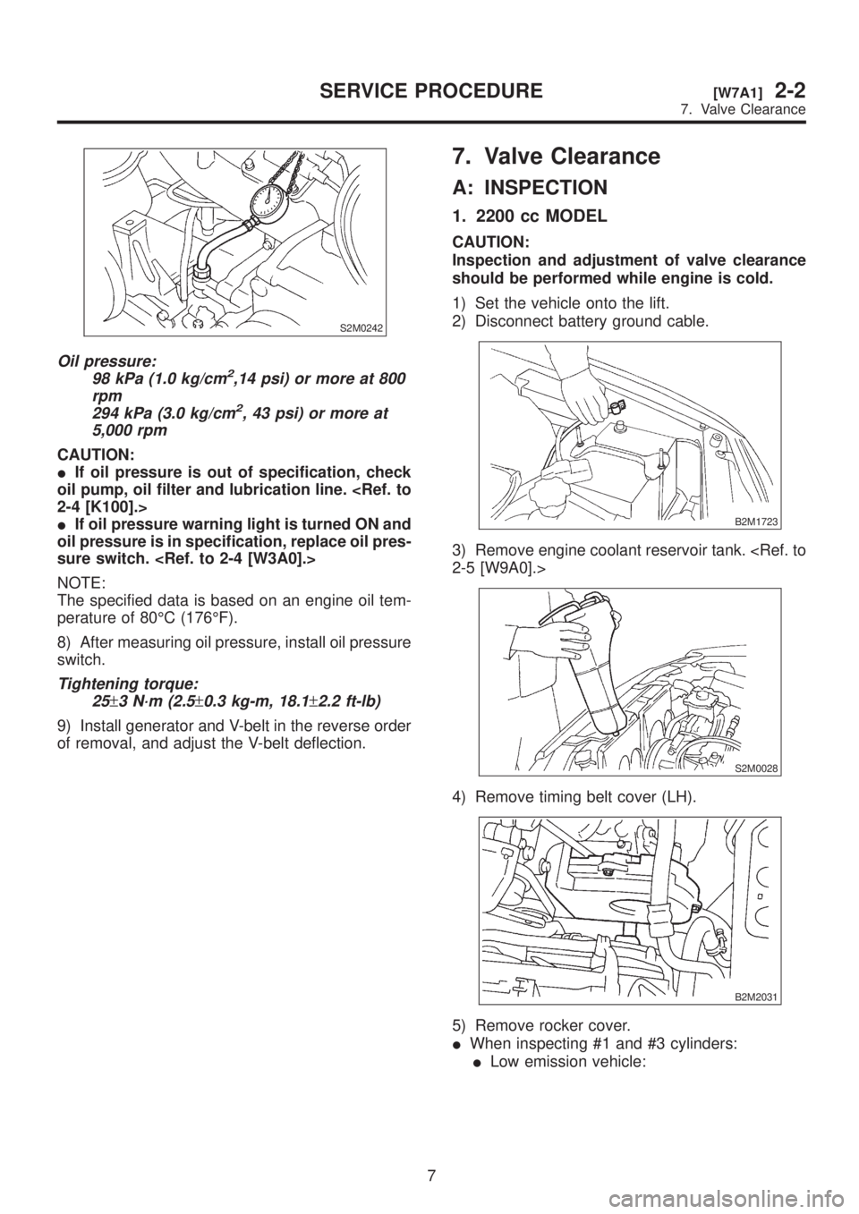
Oil pressure:
98 kPa (1.0 kg/cm2,14 psi) or more at 800
rpm
294 kPa (3.0 kg/cm
2, 43 psi) or more at
5,000 rpm
CAUTION:
IIf oil pressure is out of specification, check
oil pump, oil filter and lubrication line.
IIf oil pressure warning light is turned ON and
oil pressure is in specification, replace oil pres-
sure switch.
NOTE:
The specified data is based on an engine oil tem-
perature of 80ÉC (176ÉF).
8) After measuring oil pressure, install oil pressure
switch.
Tightening torque:
25
±3 N´m (2.5±0.3 kg-m, 18.1±2.2 ft-lb)
9) Install generator and V-belt in the reverse order
of removal, and adjust the V-belt deflection.
7. Valve Clearance
A: INSPECTION
1. 2200 cc MODEL
CAUTION:
Inspection and adjustment of valve clearance
should be performed while engine is cold.
1) Set the vehicle onto the lift.
2) Disconnect battery ground cable.
B2M1723
3) Remove engine coolant reservoir tank.
S2M0028
4) Remove timing belt cover (LH).
B2M2031
5) Remove rocker cover.
IWhen inspecting #1 and #3 cylinders:
ILow emission vehicle:
7
[W7A1]2-2SERVICE PROCEDURE
7. Valve Clearance
Page 43 of 1456
S2M0242
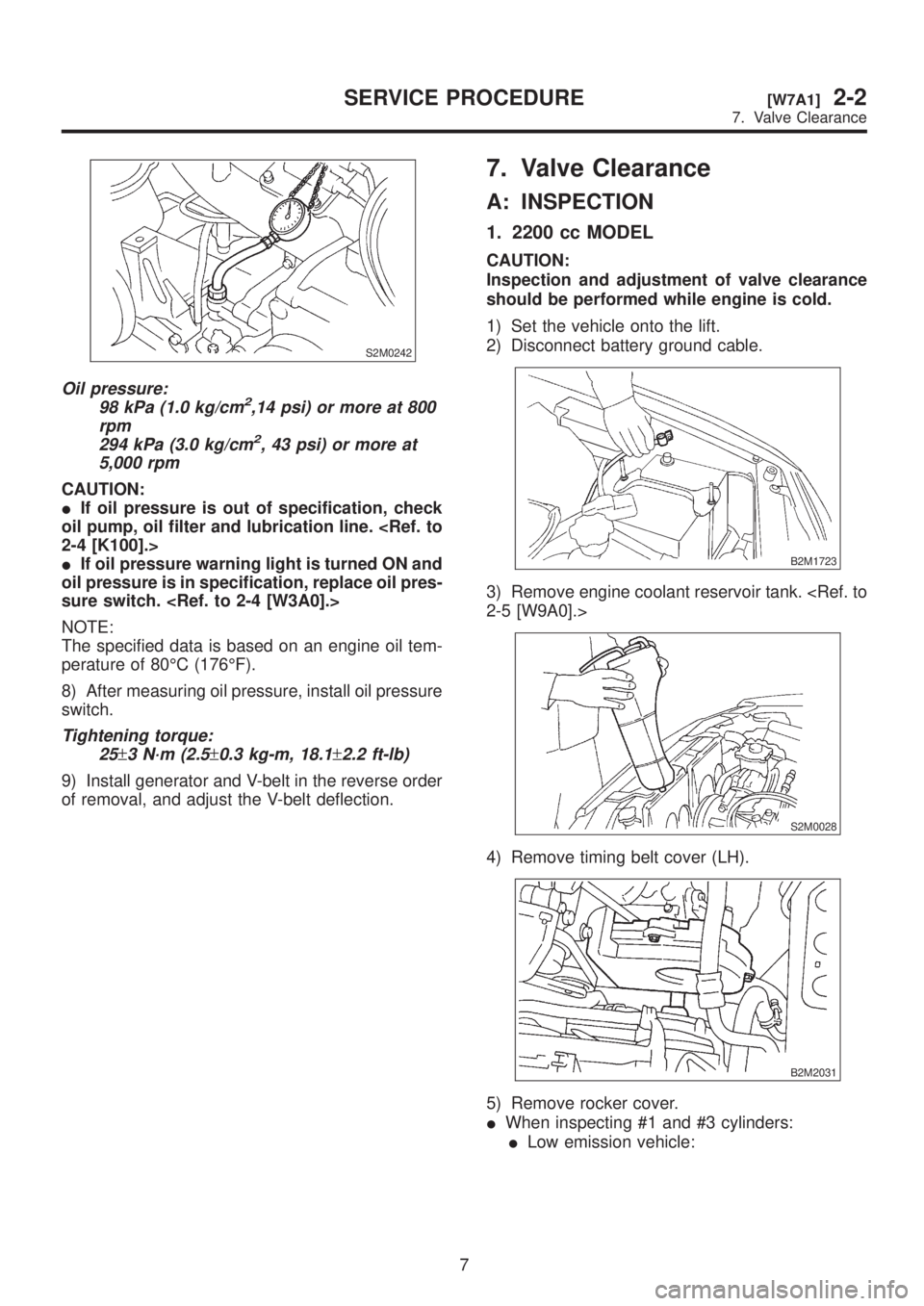
Oil pressure:
98 kPa (1.0 kg/cm2,14 psi) or more at 800
rpm
294 kPa (3.0 kg/cm
2, 43 psi) or more at
5,000 rpm
CAUTION:
IIf oil pressure is out of specification, check
oil pump, oil filter and lubrication line.
IIf oil pressure warning light is turned ON and
oil pressure is in specification, replace oil pres-
sure switch.
NOTE:
The specified data is based on an engine oil tem-
perature of 80ÉC (176ÉF).
8) After measuring oil pressure, install oil pressure
switch.
Tightening torque:
25
±3 N´m (2.5±0.3 kg-m, 18.1±2.2 ft-lb)
9) Install generator and V-belt in the reverse order
of removal, and adjust the V-belt deflection.
7. Valve Clearance
A: INSPECTION
1. 2200 cc MODEL
CAUTION:
Inspection and adjustment of valve clearance
should be performed while engine is cold.
1) Set the vehicle onto the lift.
2) Disconnect battery ground cable.
B2M1723
3) Remove engine coolant reservoir tank.
S2M0028
4) Remove timing belt cover (LH).
B2M2031
5) Remove rocker cover.
IWhen inspecting #1 and #3 cylinders:
ILow emission vehicle:
7
[W7A1]2-2SERVICE PROCEDURE
7. Valve Clearance
Page 208 of 1456
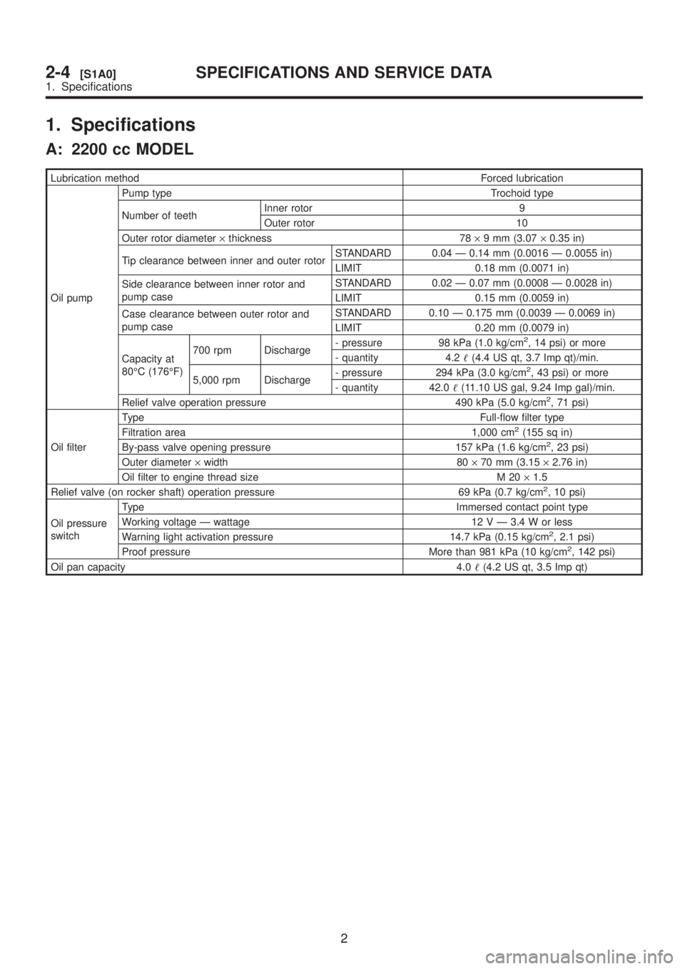
1. Specifications
A: 2200 cc MODEL
Lubrication methodForced lubrication
Oil pumpPump type Trochoid type
Number of teethInner rotor 9
Outer rotor 10
Outer rotor diameter´thickness 78´9 mm (3.07´0.35 in)
Tip clearance between inner and outer rotorSTANDARD 0.04 Ð 0.14 mm (0.0016 Ð 0.0055 in)
LIMIT 0.18 mm (0.0071 in)
Side clearance between inner rotor and
pump caseSTANDARD 0.02 Ð 0.07 mm (0.0008 Ð 0.0028 in)
LIMIT 0.15 mm (0.0059 in)
Case clearance between outer rotor and
pump caseSTANDARD 0.10 Ð 0.175 mm (0.0039 Ð 0.0069 in)
LIMIT 0.20 mm (0.0079 in)
Capacity at
80ÉC (176ÉF)700 rpm Discharge- pressure 98 kPa (1.0 kg/cm
2, 14 psi) or more
- quantity 4.2(4.4 US qt, 3.7 Imp qt)/min.
5,000 rpm Discharge- pressure 294 kPa (3.0 kg/cm
2, 43 psi) or more
- quantity 42.0(11.10 US gal, 9.24 Imp gal)/min.
Relief valve operation pressure 490 kPa (5.0 kg/cm
2, 71 psi)
Oil filterTypeFull-flow filter type
Filtration area 1,000 cm
2(155 sq in)
By-pass valve opening pressure 157 kPa (1.6 kg/cm2, 23 psi)
Outer diameter´width 80´70 mm (3.15´2.76 in)
Oil filter to engine thread size M 20´1.5
Relief valve (on rocker shaft) operation pressure 69 kPa (0.7 kg/cm
2, 10 psi)
Oil pressure
switchType Immersed contact point type
Working voltage Ð wattage 12 V Ð 3.4 W or less
Warning light activation pressure 14.7 kPa (0.15 kg/cm
2, 2.1 psi)
Proof pressure More than 981 kPa (10 kg/cm2, 142 psi)
Oil pan capacity4.0(4.2 US qt, 3.5 Imp qt)
2
2-4[S1A0]SPECIFICATIONS AND SERVICE DATA
1. Specifications
Page 209 of 1456
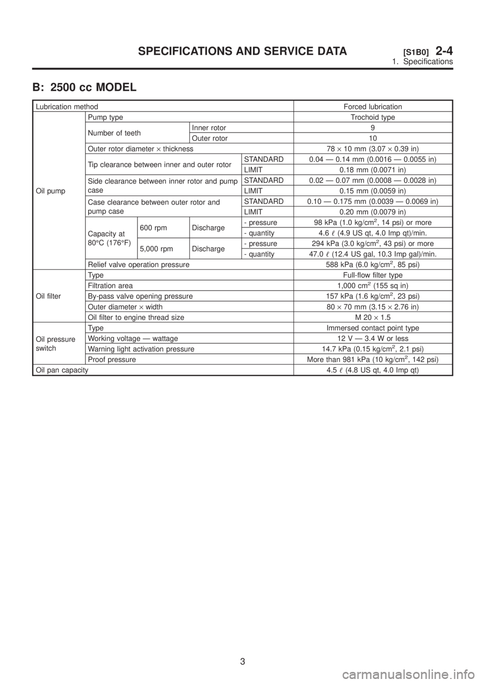
B: 2500 cc MODEL
Lubrication methodForced lubrication
Oil pumpPump type Trochoid type
Number of teethInner rotor 9
Outer rotor 10
Outer rotor diameter´thickness 78´10 mm (3.07´0.39 in)
Tip clearance between inner and outer rotorSTANDARD 0.04 Ð 0.14 mm (0.0016 Ð 0.0055 in)
LIMIT 0.18 mm (0.0071 in)
Side clearance between inner rotor and pump
caseSTANDARD 0.02 Ð 0.07 mm (0.0008 Ð 0.0028 in)
LIMIT 0.15 mm (0.0059 in)
Case clearance between outer rotor and
pump caseSTANDARD 0.10 Ð 0.175 mm (0.0039 Ð 0.0069 in)
LIMIT 0.20 mm (0.0079 in)
Capacity at
80ÉC (176ÉF)600 rpm Discharge- pressure 98 kPa (1.0 kg/cm
2, 14 psi) or more
- quantity 4.6(4.9 US qt, 4.0 Imp qt)/min.
5,000 rpm Discharge- pressure 294 kPa (3.0 kg/cm
2, 43 psi) or more
- quantity 47.0(12.4 US gal, 10.3 Imp gal)/min.
Relief valve operation pressure 588 kPa (6.0 kg/cm
2, 85 psi)
Oil filterTypeFull-flow filter type
Filtration area 1,000 cm
2(155 sq in)
By-pass valve opening pressure 157 kPa (1.6 kg/cm2, 23 psi)
Outer diameter´width 80´70 mm (3.15´2.76 in)
Oil filter to engine thread size M 20´1.5
Oil pressure
switchType Immersed contact point type
Working voltage Ð wattage 12 V Ð 3.4 W or less
Warning light activation pressure 14.7 kPa (0.15 kg/cm
2, 2.1 psi)
Proof pressure More than 981 kPa (10 kg/cm2, 142 psi)
Oil pan capacity4.5(4.8 US qt, 4.0 Imp qt)
3
[S1B0]2-4SPECIFICATIONS AND SERVICE DATA
1. Specifications
Page 227 of 1456
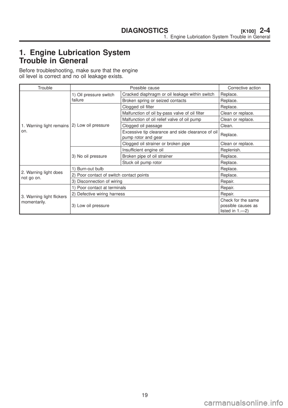
1. Engine Lubrication System
Trouble in General
Before troubleshooting, make sure that the engine
oil level is correct and no oil leakage exists.
Trouble Possible cause Corrective action
1. Warning light remains
on.1) Oil pressure switch
failureCracked diaphragm or oil leakage within switch Replace.
Broken spring or seized contacts Replace.
2) Low oil pressureClogged oil filter Replace.
Malfunction of oil by-pass valve of oil filter Clean or replace.
Malfunction of oil relief valve of oil pump Clean or replace.
Clogged oil passage Clean.
Excessive tip clearance and side clearance of oil
pump rotor and gearReplace.
Clogged oil strainer or broken pipe Clean or replace.
3) No oil pressureInsufficient engine oil Replenish.
Broken pipe of oil strainer Replace.
Stuck oil pump rotor Replace.
2. Warning light does
not go on.1) Burn-out bulb Replace.
2) Poor contact of switch contact points Replace.
3) Disconnection of wiring Repair.
3. Warning light flickers
momentarily.1) Poor contact at terminals Repair.
2) Defective wiring harness Repair.
3) Low oil pressureCheck for the same
possible causes as
listed in 1.Ð2)
19
[K100]2-4DIAGNOSTICS
1. Engine Lubrication System Trouble in General
Page 648 of 1456
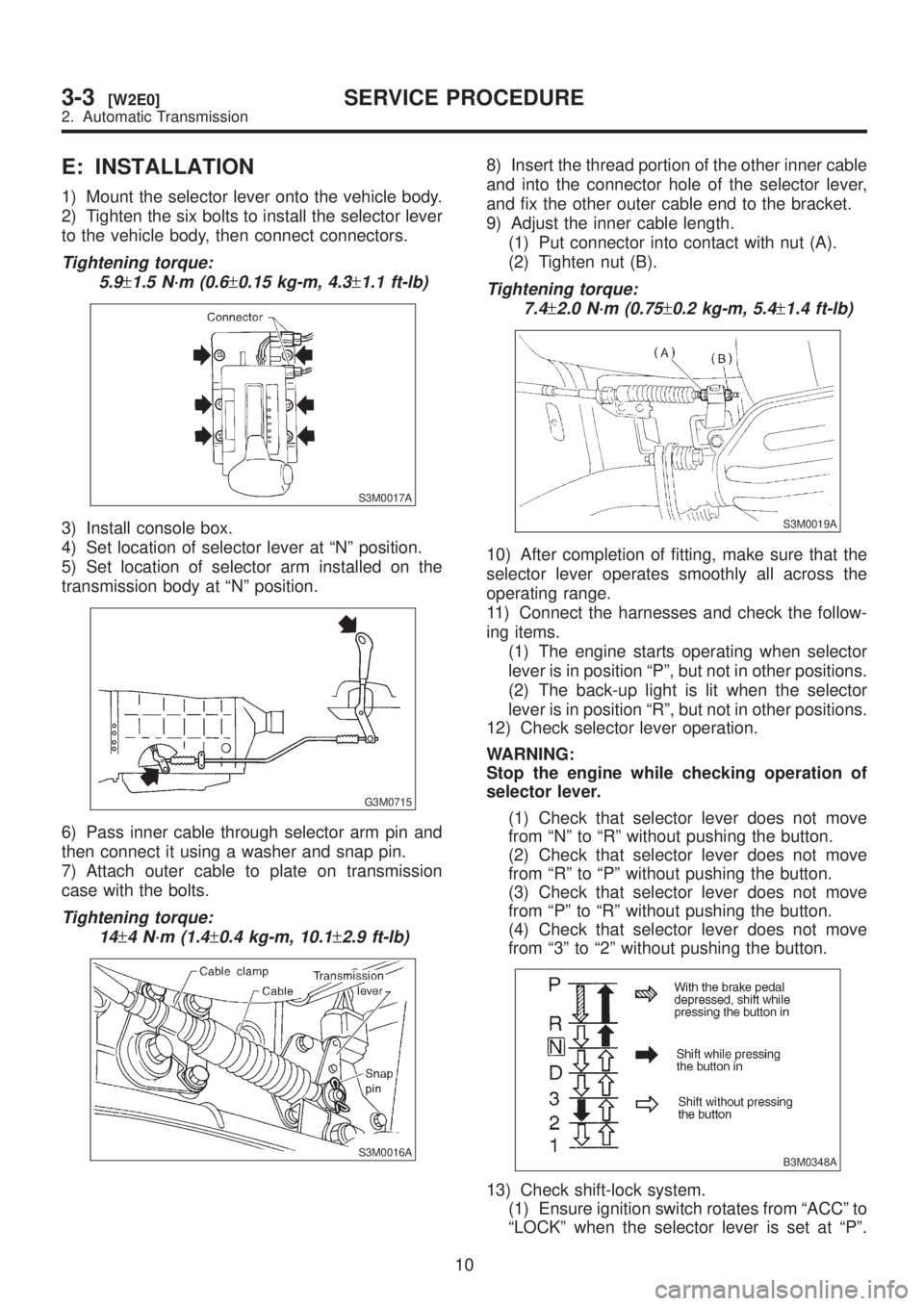
E: INSTALLATION
1) Mount the selector lever onto the vehicle body.
2) Tighten the six bolts to install the selector lever
to the vehicle body, then connect connectors.
Tightening torque:
5.9
±1.5 N´m (0.6±0.15 kg-m, 4.3±1.1 ft-lb)
S3M0017A
3) Install console box.
4) Set location of selector lever at ªNº position.
5) Set location of selector arm installed on the
transmission body at ªNº position.
G3M0715
6) Pass inner cable through selector arm pin and
then connect it using a washer and snap pin.
7) Attach outer cable to plate on transmission
case with the bolts.
Tightening torque:
14
±4 N´m (1.4±0.4 kg-m, 10.1±2.9 ft-lb)
S3M0016A
8) Insert the thread portion of the other inner cable
and into the connector hole of the selector lever,
and fix the other outer cable end to the bracket.
9) Adjust the inner cable length.
(1) Put connector into contact with nut (A).
(2) Tighten nut (B).
Tightening torque:
7.4
±2.0 N´m (0.75±0.2 kg-m, 5.4±1.4 ft-lb)
S3M0019A
10) After completion of fitting, make sure that the
selector lever operates smoothly all across the
operating range.
11) Connect the harnesses and check the follow-
ing items.
(1) The engine starts operating when selector
lever is in position ªPº, but not in other positions.
(2) The back-up light is lit when the selector
lever is in position ªRº, but not in other positions.
12) Check selector lever operation.
WARNING:
Stop the engine while checking operation of
selector lever.
(1) Check that selector lever does not move
from ªNº to ªRº without pushing the button.
(2) Check that selector lever does not move
from ªRº to ªPº without pushing the button.
(3) Check that selector lever does not move
from ªPº to ªRº without pushing the button.
(4) Check that selector lever does not move
from ª3º to ª2º without pushing the button.
B3M0348A
13) Check shift-lock system.
(1) Ensure ignition switch rotates from ªACCº to
ªLOCKº when the selector lever is set at ªPº.
10
3-3[W2E0]SERVICE PROCEDURE
2. Automatic Transmission
Page 935 of 1456
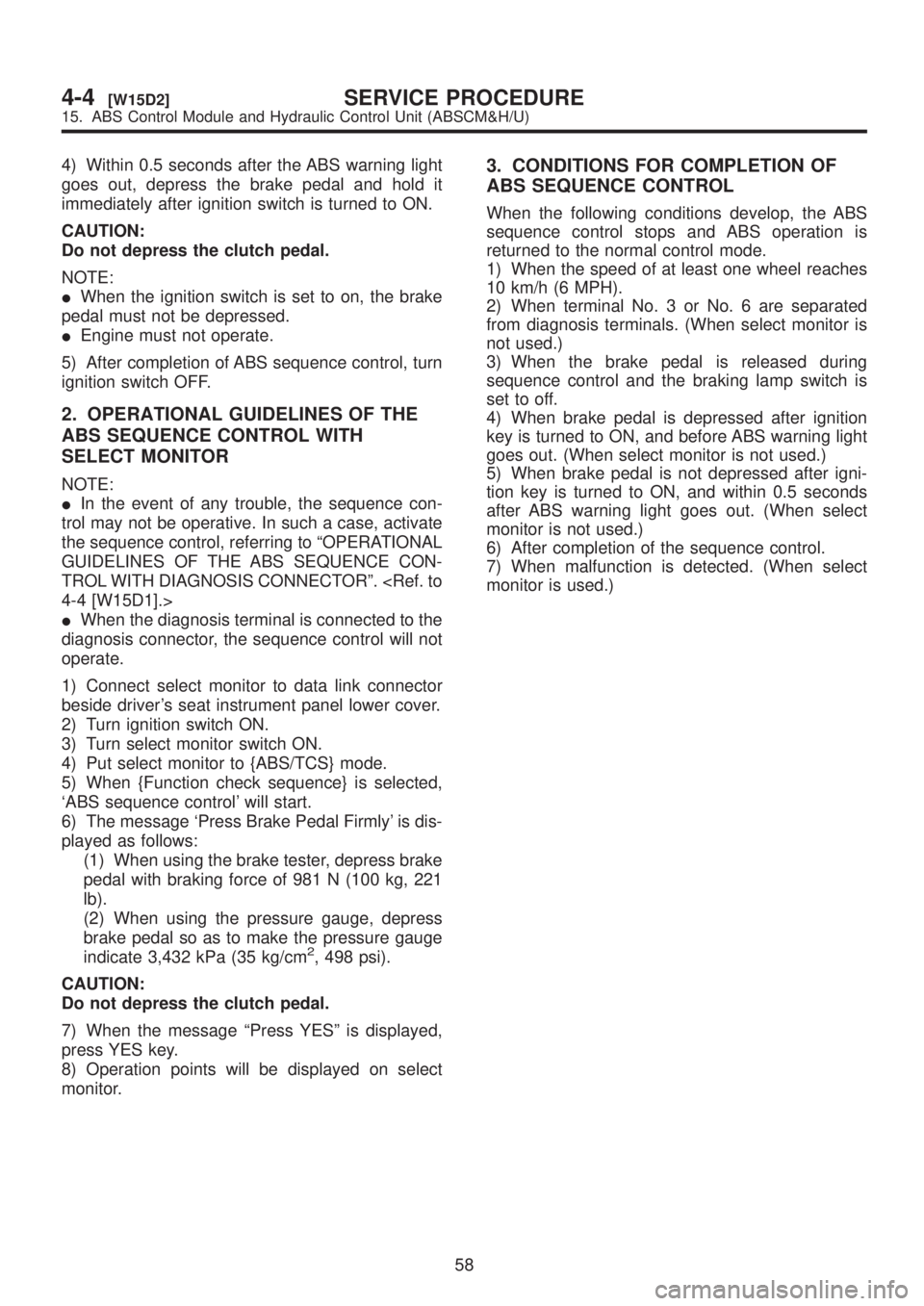
4) Within 0.5 seconds after the ABS warning light
goes out, depress the brake pedal and hold it
immediately after ignition switch is turned to ON.
CAUTION:
Do not depress the clutch pedal.
NOTE:
IWhen the ignition switch is set to on, the brake
pedal must not be depressed.
IEngine must not operate.
5) After completion of ABS sequence control, turn
ignition switch OFF.
2. OPERATIONAL GUIDELINES OF THE
ABS SEQUENCE CONTROL WITH
SELECT MONITOR
NOTE:
IIn the event of any trouble, the sequence con-
trol may not be operative. In such a case, activate
the sequence control, referring to ªOPERATIONAL
GUIDELINES OF THE ABS SEQUENCE CON-
TROL WITH DIAGNOSIS CONNECTORº.
IWhen the diagnosis terminal is connected to the
diagnosis connector, the sequence control will not
operate.
1) Connect select monitor to data link connector
beside driver's seat instrument panel lower cover.
2) Turn ignition switch ON.
3) Turn select monitor switch ON.
4) Put select monitor to {ABS/TCS} mode.
5) When {Function check sequence} is selected,
`ABS sequence control' will start.
6) The message `Press Brake Pedal Firmly' is dis-
played as follows:
(1) When using the brake tester, depress brake
pedal with braking force of 981 N (100 kg, 221
lb).
(2) When using the pressure gauge, depress
brake pedal so as to make the pressure gauge
indicate 3,432 kPa (35 kg/cm
2, 498 psi).
CAUTION:
Do not depress the clutch pedal.
7) When the message ªPress YESº is displayed,
press YES key.
8) Operation points will be displayed on select
monitor.
3. CONDITIONS FOR COMPLETION OF
ABS SEQUENCE CONTROL
When the following conditions develop, the ABS
sequence control stops and ABS operation is
returned to the normal control mode.
1) When the speed of at least one wheel reaches
10 km/h (6 MPH).
2) When terminal No. 3 or No. 6 are separated
from diagnosis terminals. (When select monitor is
not used.)
3) When the brake pedal is released during
sequence control and the braking lamp switch is
set to off.
4) When brake pedal is depressed after ignition
key is turned to ON, and before ABS warning light
goes out. (When select monitor is not used.)
5) When brake pedal is not depressed after igni-
tion key is turned to ON, and within 0.5 seconds
after ABS warning light goes out. (When select
monitor is not used.)
6) After completion of the sequence control.
7) When malfunction is detected. (When select
monitor is used.)
58
4-4[W15D2]SERVICE PROCEDURE
15. ABS Control Module and Hydraulic Control Unit (ABSCM&H/U)
Page 1168 of 1456
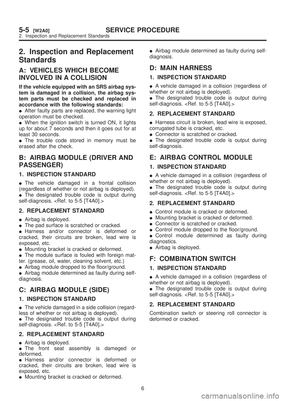
2. Inspection and Replacement
Standards
A: VEHICLES WHICH BECOME
INVOLVED IN A COLLISION
If the vehicle equipped with an SRS airbag sys-
tem is damaged in a collision, the airbag sys-
tem parts must be checked and replaced in
accordance with the following standards:
IAfter faulty parts are replaced, the warning light
operation must be checked.
IWhen the ignition switch is turned ON, it lights
up for about 7 seconds and then it goes out for at
least 30 seconds.
IThe trouble code stored in memory must be
erased after the check.
B: AIRBAG MODULE (DRIVER AND
PASSENGER)
1. INSPECTION STANDARD
IThe vehicle damaged in a frontal collision
(regardless of whether or not airbag is deployed).
IThe designated trouble code is output during
self-diagnosis.
2. REPLACEMENT STANDARD
IAirbag is deployed.
IThe pad surface is scratched or cracked.
IHarness and/or connector is deformed or
cracked, their circuits are broken, lead wire is
exposed, etc.
IMounting bracket is cracked or deformed.
IThe module surface is fouled with foreign mat-
ter. (grease, oil, water, cleaning solvent, etc.)
IAirbag module dropped to the floor/ground.
IAirbag module determined as faulty during self-
diagnosis.
C: AIRBAG MODULE (SIDE)
1. INSPECTION STANDARD
IThe vehicle damaged in a side collision (regard-
less of whether or not airbag is deployed).
IThe designated trouble code is output during
self-diagnosis.
2. REPLACEMENT STANDARD
IAirbag is deployed.
IThe front seat assembly is dameged or
deformed.
IHarness and/or connector is deformed or
cracked, their circuits are broken, lead wire is
exposed, etc.
IMounting bracket is cracked or deformed.IAirbag module determined as faulty during self-
diagnosis.
D: MAIN HARNESS
1. INSPECTION STANDARD
IA vehicle damaged in a collision (regardless of
whether or not airbag is deployed).
IThe designated trouble code is output during
self-diagnosis.
2. REPLACEMENT STANDARD
IHarness circuit is broken, lead wire is exposed,
corrugated tube is cracked, etc.
IConnector is scratched or cracked.
IThe designated trouble code is output during
self-diagnosis.
E: AIRBAG CONTROL MODULE
1. INSPECTION STANDARD
IA vehicle damaged in a collision (regardless of
whether or not airbag is deployed).
IThe designated trouble code is output during
self-diagnosis.
2. REPLACEMENT STANDARD
IControl module is cracked or deformed.
IMounting bracket is cracked or deformed.
IConnector is scratched or cracked.
IControl module dropped to the floor/ground.
IControl module determined as faulty during
diagnostics.
IAirbag is deployed.
F: COMBINATION SWITCH
1. INSPECTION STANDARD
IA vehicle damaged in a collision (regardless of
whether or not airbag is deployed).
IThe designated trouble code is output during
self-diagnosis.
2. REPLACEMENT STANDARD
Combination switch or steering roll connector is
deformed or cracked.
6
5-5[W2A0]SERVICE PROCEDURE
2. Inspection and Replacement Standards