Page 528 of 1456

Automatic
transmis-
sionTransmis-
sionSelector positionP (Park)Transmission in
neutral, output mem-
ber immovable, and
engine start possible
R (Reverse)Transmission in
reverse for backing
N (Neutral)Transmission in
neutral, and engine
start possible
D (Drive)Automatic gear
change
1st
¬
®2nd¬
®3rd¬
®4th
3 (3rd)Automatic gear
change
1st
¬
®2nd¬
®3rd
¬4th
2 (2nd)2nd gear locked
(Deceleration pos-
sible 4th®3rd®
2nd)
1 (1st)1st gear locked
(Deceleration pos-
sible 4th®3rd®
2nd®1st)
Control method Hydraulic remote control
Oil pumpType Trochoid constant-displacement pump
Driving method Driven by engine
Number of teethInner rotor 9
Outer rotor 10
Hydraulic
controlTypeElectronic/hydraulic control [Four forward speed changes by electri-
cal signals of vehicle speed and accelerator (throttle) opening]
Fluid Dexron II or Dexron III type Automatic transmission fluid
Fluid capacity2200 cc 8.4 Ð 8.7(8.9 Ð 9.2 US qt, 7.4 Ð 7.7 Imp qt)
2500 cc 9.3 Ð 9.6(9.8 Ð 10.1 US qt, 8.2 Ð 8.4 Imp qt)
Lubrica-
tionLubrication system Forced feed lubrication with oil pump
Oil Automatic transmission fluid (above mentioned.)
Cooling Cooling system Liquid-cooled cooler incorporated in radiator
HarnessInhibitor switch 12 poles
Transmission harness 17 poles
TransferTransfer clutch Hydraulic multi-plate clutch
Plate number of transfer clutchDrive plate & driven
plate2200 cc 4
2500 cc 5
Control method Electronic, hydraulic type
LubricantThe same Automatic Transmission
Fluid used in automatic transmission.
1st reduction gear ratio 1.000 (53/53)
3
[S1A0]3-2SPECIFICATIONS AND SERVICE DATA
1. Automatic Transmission and Differential
Page 1080 of 1456
12. Front Grille
A: REMOVAL AND INSTALLATION
1) Remove four upper clips from body panel. To
facilitate removal, press portion shown in figure
using screwdriver.
B5M0294A
2) Pull front grille to detach it from two lower clips.
(Two lower clips remain on headlight.)
3) Installation is in the reverse order of removal.
NOTE:
Attach all clips to grille. Align them with clip hole in
body and push them into place.
13. Door Mirror
A: REMOVAL AND INSTALLATION
1) Remove the gusset cover.
B6M0146
2) Remove inner remote control switch cover.
B5M0296
3) Remove front door trim.
B5M0297
4) Remove front door trim.
55
[W13A0]5-1SERVICE PROCEDURE
13. Door Mirror
Page 1081 of 1456
12. Front Grille
A: REMOVAL AND INSTALLATION
1) Remove four upper clips from body panel. To
facilitate removal, press portion shown in figure
using screwdriver.
B5M0294A
2) Pull front grille to detach it from two lower clips.
(Two lower clips remain on headlight.)
3) Installation is in the reverse order of removal.
NOTE:
Attach all clips to grille. Align them with clip hole in
body and push them into place.
13. Door Mirror
A: REMOVAL AND INSTALLATION
1) Remove the gusset cover.
B6M0146
2) Remove inner remote control switch cover.
B5M0296
3) Remove front door trim.
B5M0297
4) Remove front door trim.
55
[W13A0]5-1SERVICE PROCEDURE
13. Door Mirror
Page 1265 of 1456

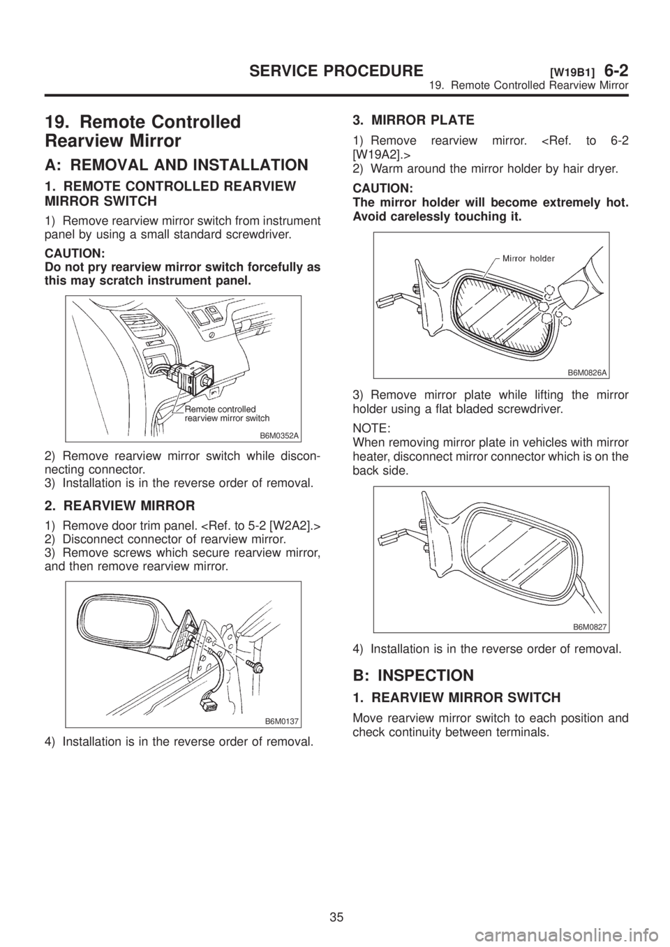
19. Remote Controlled
Rearview Mirror
A: REMOVAL AND INSTALLATION
1. REMOTE CONTROLLED REARVIEW
MIRROR SWITCH
1) Remove rearview mirror switch from instrument
panel by using a small standard screwdriver.
CAUTION:
Do not pry rearview mirror switch forcefully as
this may scratch instrument panel.
B6M0352A
2) Remove rearview mirror switch while discon-
necting connector.
3) Installation is in the reverse order of removal.
2. REARVIEW MIRROR
1) Remove door trim panel.
2) Disconnect connector of rearview mirror.
3) Remove screws which secure rearview mirror,
and then remove rearview mirror.
B6M0137
4) Installation is in the reverse order of removal.
3. MIRROR PLATE
1) Remove rearview mirror.
[W19A2].>
2) Warm around the mirror holder by hair dryer.
CAUTION:
The mirror holder will become extremely hot.
Avoid carelessly touching it.
B6M0826A
3) Remove mirror plate while lifting the mirror
holder using a flat bladed screwdriver.
NOTE:
When removing mirror plate in vehicles with mirror
heater, disconnect mirror connector which is on the
back side.
B6M0827
4) Installation is in the reverse order of removal.
B: INSPECTION
1. REARVIEW MIRROR SWITCH
Move rearview mirror switch to each position and
check continuity between terminals.
35
[W19B1]6-2SERVICE PROCEDURE
19. Remote Controlled Rearview Mirror
Page 1266 of 1456
B6M0714A
2. REARVIEW MIRROR
Check to ensure that rearview mirror moves prop-
erly when battery voltage is applied to terminals.
Operation Terminal connection
(+) (þ)
UP 3 1
DOWN 1 3
RIGHT 1 2
LEFT 2 1
B6M0140
36
6-2[W19B2]SERVICE PROCEDURE
19. Remote Controlled Rearview Mirror
Page 1296 of 1456

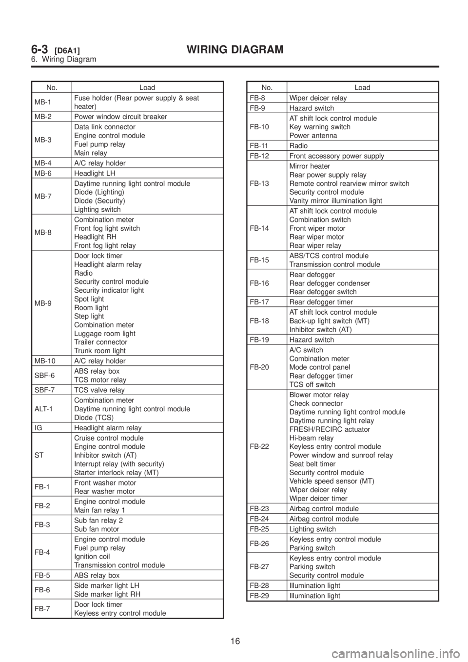
No. Load
MB-1Fuse holder (Rear power supply & seat
heater)
MB-2 Power window circuit breaker
MB-3Data link connector
Engine control module
Fuel pump relay
Main relay
MB-4 A/C relay holder
MB-6 Headlight LH
MB-7Daytime running light control module
Diode (Lighting)
Diode (Security)
Lighting switch
MB-8Combination meter
Front fog light switch
Headlight RH
Front fog light relay
MB-9Door lock timer
Headlight alarm relay
Radio
Security control module
Security indicator light
Spot light
Room light
Step light
Combination meter
Luggage room light
Trailer connector
Trunk room light
MB-10 A/C relay holder
SBF-6ABS relay box
TCS motor relay
SBF-7 TCS valve relay
ALT-1Combination meter
Daytime running light control module
Diode (TCS)
IG Headlight alarm relay
STCruise control module
Engine control module
Inhibitor switch (AT)
Interrupt relay (with security)
Starter interlock relay (MT)
FB-1Front washer motor
Rear washer motor
FB-2Engine control module
Main fan relay 1
FB-3Sub fan relay 2
Sub fan motor
FB-4Engine control module
Fuel pump relay
Ignition coil
Transmission control module
FB-5 ABS relay box
FB-6Side marker light LH
Side marker light RH
FB-7Door lock timer
Keyless entry control moduleNo. Load
FB-8 Wiper deicer relay
FB-9 Hazard switch
FB-10AT shift lock control module
Key warning switch
Power antenna
FB-11 Radio
FB-12 Front accessory power supply
FB-13Mirror heater
Rear power supply relay
Remote control rearview mirror switch
Security control module
Vanity mirror illumination light
FB-14AT shift lock control module
Combination switch
Front wiper motor
Rear wiper motor
Rear wiper relay
FB-15ABS/TCS control module
Transmission control module
FB-16Rear defogger
Rear defogger condenser
Rear defogger switch
FB-17 Rear defogger timer
FB-18AT shift lock control module
Back-up light switch (MT)
Inhibitor switch (AT)
FB-19 Hazard switch
FB-20A/C switch
Combination meter
Mode control panel
Rear defogger timer
TCS off switch
FB-22Blower motor relay
Check connector
Daytime running light control module
Daytime running light relay
FRESH/RECIRC actuator
Hi-beam relay
Keyless entry control module
Power window and sunroof relay
Seat belt timer
Security control module
Vehicle speed sensor (MT)
Wiper deicer relay
Wiper deicer timer
FB-23 Airbag control module
FB-24 Airbag control module
FB-25 Lighting switch
FB-26Keyless entry control module
Parking switch
FB-27Keyless entry control module
Parking switch
Security control module
FB-28 Illumination light
FB-29 Illumination light
16
6-3[D6A1]WIRING DIAGRAM
6. Wiring Diagram
Page 1300 of 1456

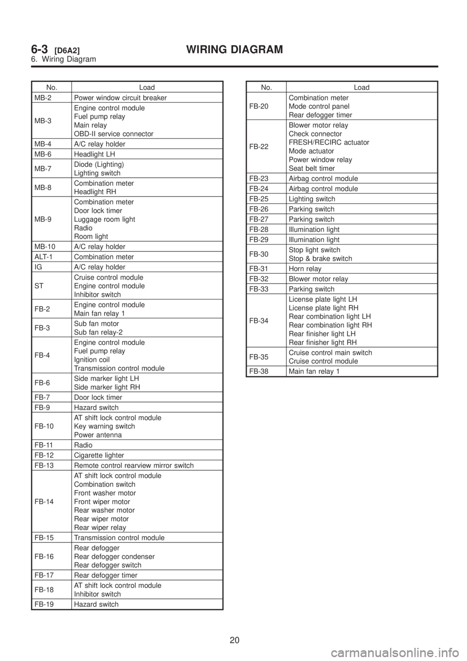
No. Load
MB-2 Power window circuit breaker
MB-3Engine control module
Fuel pump relay
Main relay
OBD-II service connector
MB-4 A/C relay holder
MB-6 Headlight LH
MB-7Diode (Lighting)
Lighting switch
MB-8Combination meter
Headlight RH
MB-9Combination meter
Door lock timer
Luggage room light
Radio
Room light
MB-10 A/C relay holder
ALT-1 Combination meter
IG A/C relay holder
STCruise control module
Engine control module
Inhibitor switch
FB-2Engine control module
Main fan relay 1
FB-3Sub fan motor
Sub fan relay-2
FB-4Engine control module
Fuel pump relay
Ignition coil
Transmission control module
FB-6Side marker light LH
Side marker light RH
FB-7 Door lock timer
FB-9 Hazard switch
FB-10AT shift lock control module
Key warning switch
Power antenna
FB-11 Radio
FB-12 Cigarette lighter
FB-13 Remote control rearview mirror switch
FB-14AT shift lock control module
Combination switch
Front washer motor
Front wiper motor
Rear washer motor
Rear wiper motor
Rear wiper relay
FB-15 Transmission control module
FB-16Rear defogger
Rear defogger condenser
Rear defogger switch
FB-17 Rear defogger timer
FB-18AT shift lock control module
Inhibitor switch
FB-19 Hazard switchNo. Load
FB-20Combination meter
Mode control panel
Rear defogger timer
FB-22Blower motor relay
Check connector
FRESH/RECIRC actuator
Mode actuator
Power window relay
Seat belt timer
FB-23 Airbag control module
FB-24 Airbag control module
FB-25 Lighting switch
FB-26 Parking switch
FB-27 Parking switch
FB-28 Illumination light
FB-29 Illumination light
FB-30Stop light switch
Stop & brake switch
FB-31 Horn relay
FB-32 Blower motor relay
FB-33 Parking switch
FB-34License plate light LH
License plate light RH
Rear combination light LH
Rear combination light RH
Rear finisher light LH
Rear finisher light RH
FB-35Cruise control main switch
Cruise control module
FB-38 Main fan relay 1
20
6-3[D6A2]WIRING DIAGRAM
6. Wiring Diagram
Page 1392 of 1456
AB: REMOTE CONTROLLED REARVIEW MIRROR SYSTEM
1. LHD MODEL
11 2
6-3[D6AB1]WIRING DIAGRAM
6. Wiring Diagram