1999 SUBARU LEGACY brake light
[x] Cancel search: brake lightPage 426 of 1456
![SUBARU LEGACY 1999 Service Repair Manual 5. Operating Cylinder
A: REMOVAL AND INSTALLATION
1) Remove air chamber.
<Ref. to 2-7 [W18A0].>
B2M1265
2) Remove clutch hose from operating cylinder.
CAUTION:
Cover hose joint to prevent brake fluid SUBARU LEGACY 1999 Service Repair Manual 5. Operating Cylinder
A: REMOVAL AND INSTALLATION
1) Remove air chamber.
<Ref. to 2-7 [W18A0].>
B2M1265
2) Remove clutch hose from operating cylinder.
CAUTION:
Cover hose joint to prevent brake fluid](/manual-img/17/57435/w960_57435-425.png)
5. Operating Cylinder
A: REMOVAL AND INSTALLATION
1) Remove air chamber.
B2M1265
2) Remove clutch hose from operating cylinder.
CAUTION:
Cover hose joint to prevent brake fluid from
flowing out.
B2M1179B
3) Remove operating cylinder from transmission.
B2M1263
4) Installation is in the reverse order of removal.
NOTE:
Before installing operating cylinder, apply grease
(SUNLIGHT 2: P/N 003602010) to contact point of
release lever and operating cylinder.
Tightening torque:
T1: 18
±3 N´m (1.8±0.3 kg-m, 13.0±2.2 ft-lb)
T2: 37
±3 N´m (3.8±0.3 kg-m, 27.5±2.2 ft-lb)
B2M1179C
5) After bleeding air from operating cylinder,
ensure that clutch operates properly.
15
[W5A0]2-10SERVICE PROCEDURE
5. Operating Cylinder
Page 609 of 1456

7) Tighten bolts.
Tightening torque:
8
±1 N´m (0.8±0.1 kg-m, 5.8±0.7 ft-lb)
B3M1130A
(A) Short bolts
(B) Middle bolts
(C) Long bolt
(D) Reamer bolts
8) Install the sensor, solenoids and duty solenoid
S.
Tightening torque:
T: 8
±1 N´m (0.8±0.1 kg-m, 5.8±0.7 ft-lb)
B3M1039B
(A) Lock-up duty solenoid (Blue)
(B) Low clutch timing solenoid (Gray)
(C) Line pressure duty solenoid (Red)
(D) Shift solenoid 1 (Yellow)
(E) Shift solenoid 2 (Green)
(F) 2-4 brake timing solenoid (Black)
(G) 2-4 brake duty solenoid D (Red)
(H) ATF temperature sensor
9) Install oil strainer to lower valve body.
Tightening torque:
8
±1 N´m (0.8±0.1 kg-m, 5.8±0.7 ft-lb)
15. Oil Pump Assembly
A: DISASSEMBLY
1) Remove the oil seal retainer.
Also remove the O-ring and oil seal (air breather).
B3M1094A
2) Remove O-rings from oil pump housing.
CAUTION:
Be careful not to damage O-ring.
3) Remove four seal rings.
CAUTION:
Be careful not to damage O-ring.
B3M1095A
4) Remove the oil pump cover.
NOTE:
Lightly tap the end of the stator shaft to remove the
cover.
B3M1139A
80
3-2[W15A0]SERVICE PROCEDURE
15. Oil Pump Assembly
Page 610 of 1456

7) Tighten bolts.
Tightening torque:
8
±1 N´m (0.8±0.1 kg-m, 5.8±0.7 ft-lb)
B3M1130A
(A) Short bolts
(B) Middle bolts
(C) Long bolt
(D) Reamer bolts
8) Install the sensor, solenoids and duty solenoid
S.
Tightening torque:
T: 8
±1 N´m (0.8±0.1 kg-m, 5.8±0.7 ft-lb)
B3M1039B
(A) Lock-up duty solenoid (Blue)
(B) Low clutch timing solenoid (Gray)
(C) Line pressure duty solenoid (Red)
(D) Shift solenoid 1 (Yellow)
(E) Shift solenoid 2 (Green)
(F) 2-4 brake timing solenoid (Black)
(G) 2-4 brake duty solenoid D (Red)
(H) ATF temperature sensor
9) Install oil strainer to lower valve body.
Tightening torque:
8
±1 N´m (0.8±0.1 kg-m, 5.8±0.7 ft-lb)
15. Oil Pump Assembly
A: DISASSEMBLY
1) Remove the oil seal retainer.
Also remove the O-ring and oil seal (air breather).
B3M1094A
2) Remove O-rings from oil pump housing.
CAUTION:
Be careful not to damage O-ring.
3) Remove four seal rings.
CAUTION:
Be careful not to damage O-ring.
B3M1095A
4) Remove the oil pump cover.
NOTE:
Lightly tap the end of the stator shaft to remove the
cover.
B3M1139A
80
3-2[W15A0]SERVICE PROCEDURE
15. Oil Pump Assembly
Page 697 of 1456

Adjusting direction of drive pinion
Adjusting direction of crown gear
TOOTH CONTACT PATTERN
Condition Contact pattern Adjustment
Correct tooth contact
Tooth contact pattern slightly shifted
towards toe under no load rotation.
(When loaded, contact pattern
moves toward heel.)
G3M0098A
Ð
Face contact
Backlash is too large.This may cause noise and chipping at
tooth ends.
G3M0098B
Increase thickness of drive pinion height
adjusting washer in order to bring drive
pinion closer to crown gear center.
G3M0098F
Flank contact
Backlash is too small.This may cause noise and stepped wear
on surfaces.
G3M0098C
Reduce thickness of drive pinion height
adjusting washer in order to move drive
pinion away from crown gear.
G3M0098G
Toe contact Contact area is small.
This may cause chipping at toe ends.
G3M0098D
Adjust as for flank contact.
G3M0098G
Heel contact Contact area is small.
This may cause chipping at heel ends.
G3M0098E
Adjust as for face contact
G3M0098F
F: INSTALLATION
To install, reverse the removal sequence.
1) Install the air breather cap tapping with a plas-
tic hammer.CAUTION:
Be sure to install new air breather cap.
2) Position front member on body by passing it
under parking brake cable and securing to rear
differential.
47
[W2F0]3-4SERVICE PROCEDURE
2. Rear Differential
Page 868 of 1456

Fluid leaking area Possible cause Corrective action
Leakage from connecting portions of
pipes and hoses, numbered with (1) thru
(9) in figureInsufficient tightening of flare nut, catch-
ing dirt or the like, damage to flare or
flare nutLoosen and retighten, if ineffective,
replace.
Poor insertion of hose, poor clamping Retighten or replace clamp.
Damaged O-ring Replace O-ring pipe or hose with new
one, if ineffective, replace gearbox also.
Leakage from hose (10) and (11) in fig-
ureCrack or damage in hose Replace with a new one.
Crack or damage in hose hardware Replace with a new one.
Leakage from surrounding of cast iron
portion of oil pump (12) and (13) in fig-
ureDamaged O-ring Replace O-ring.
Damaged gasket Replace gasket.
Leakage from oil tank, (14) and (15) in
figureCrack in oil tank, (14) Replace oil tank.
Damaged O-ring, (15) Replace O-ring.
Leakage from filler neck (16) Damaged cap packing Replace cap.
Crack in root of filler neck Replace oil tank.
High fluid level *1 Adjust fluid level.
Leakage from surrounding of power cyl-
inder of gearbox, (17) in figureDamaged oil seal Replace oil seal.
Leakage from control valve of gearbox,
(18) and (19) in figureDamaged packing or oil seal Replace problem parts.
Damage in control valve Replace control valve.
*1 Fluid level is specified at optimum position (range) for ordinary use. Accordingly, if the vehicle is used often under hard
conditions such as on very rough roads or in mountainous areas, fluid may bleed out from cap air vent hole. This is not
a problem. If a customer complains strongly and is not likely to be satisfied with the leakage, lower the fluid level to the
extent that fluid will not bleed out under the conditions described, and have the customer check the fluid level and its
quality more frequency than usual.
E: NOISE AND VIBRATION
CAUTION:
Don't keep the relief valve operated over 5 sec-
onds at any time or inner parts of the oil pump
may be damaged due to rapid increase of fluid
temperature.
NOTE:
IGrinding noise may be heard immediately after
the engine start in extremely cold condition. In this
case, if the noise goes off during warm-up there is
no abnormal function in the system. This is due to
the fluid characteristic in extremely cold condition.
IOil pump makes whine or growl noise slightly
due to its mechanism. Even if the noise can be
heard when steering wheel is turned at stand still
there is no abnormal function in the system pro-
vided that the noise eliminates when the vehicle is
running.
IWhen stopping with service brake and/or park-
ing brake applied, power steering can be operated
easily due to its light steering effort. If doing so, thedisk rotates slightly and makes creaking noise. The
noise is generated by creaking between the disk
and pads. If the noise goes off when the brake is
released, there is no abnormal function in the sys-
tem.
IThere may be a little vibration around the steer-
ing devices when turning steering wheel at
standstill, even though the component parts are
properly adjusted and have no defects.
Hydraulic systems are likely to generate this kind
of vibration as well as working noise and fluid noise
because of combined conditions, i.e., road surface
and tire surface, engine speed and turning speed
of steering wheel, fluid temperature and braking
condition.
This phenomena does not indicate there is some
abnormal function in the system.
The vibration can be known when steering wheel
is turned repeatedly at various speeds from slow to
rapid step by step with parking brake applied on
concrete road and in ªDº range for automatic trans-
mission vehicle.
Trouble Possible cause Corrective action
Hiss noise (continuous)
While engine is running.Relief valve emits operating sound when steering wheel is
completely turned in either direction. (Don't keep this condition
over 5 seconds.)Normal
Relief valve emits operating sound when steering wheel is not
turned. This means that the relief valve is faulty.Defective
Replace oil pump.
74
4-3[K1E0]DIAGNOSTICS
1. Power Steering
Page 871 of 1456

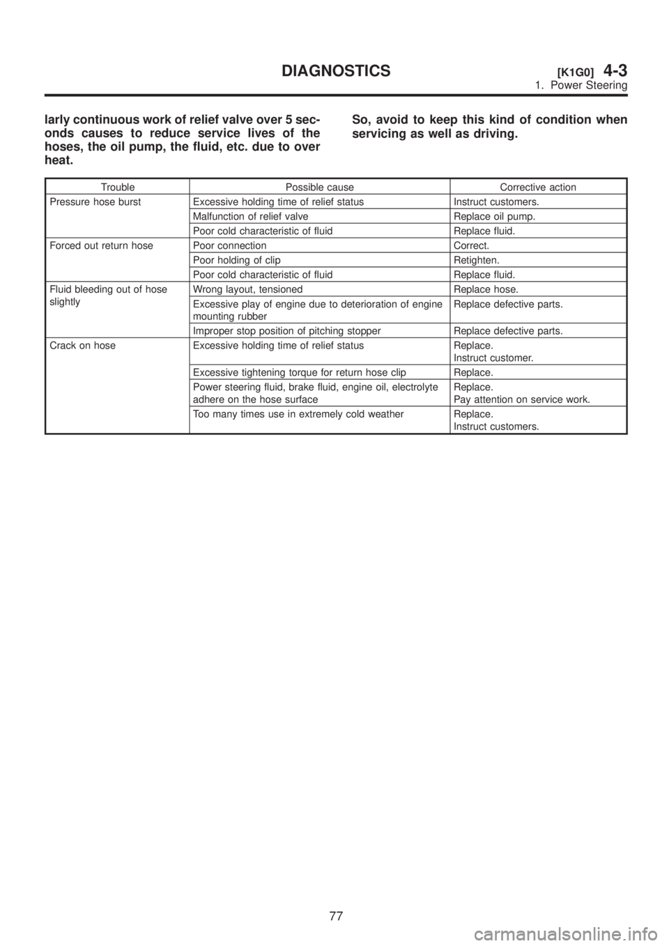
larly continuous work of relief valve over 5 sec-
onds causes to reduce service lives of the
hoses, the oil pump, the fluid, etc. due to over
heat.So, avoid to keep this kind of condition when
servicing as well as driving.
Trouble Possible cause Corrective action
Pressure hose burst Excessive holding time of relief status Instruct customers.
Malfunction of relief valve Replace oil pump.
Poor cold characteristic of fluid Replace fluid.
Forced out return hose Poor connection Correct.
Poor holding of clip Retighten.
Poor cold characteristic of fluid Replace fluid.
Fluid bleeding out of hose
slightlyWrong layout, tensioned Replace hose.
Excessive play of engine due to deterioration of engine
mounting rubberReplace defective parts.
Improper stop position of pitching stopper Replace defective parts.
Crack on hose Excessive holding time of relief status Replace.
Instruct customer.
Excessive tightening torque for return hose clip Replace.
Power steering fluid, brake fluid, engine oil, electrolyte
adhere on the hose surfaceReplace.
Pay attention on service work.
Too many times use in extremely cold weather Replace.
Instruct customers.
77
[K1G0]4-3DIAGNOSTICS
1. Power Steering
Page 876 of 1456

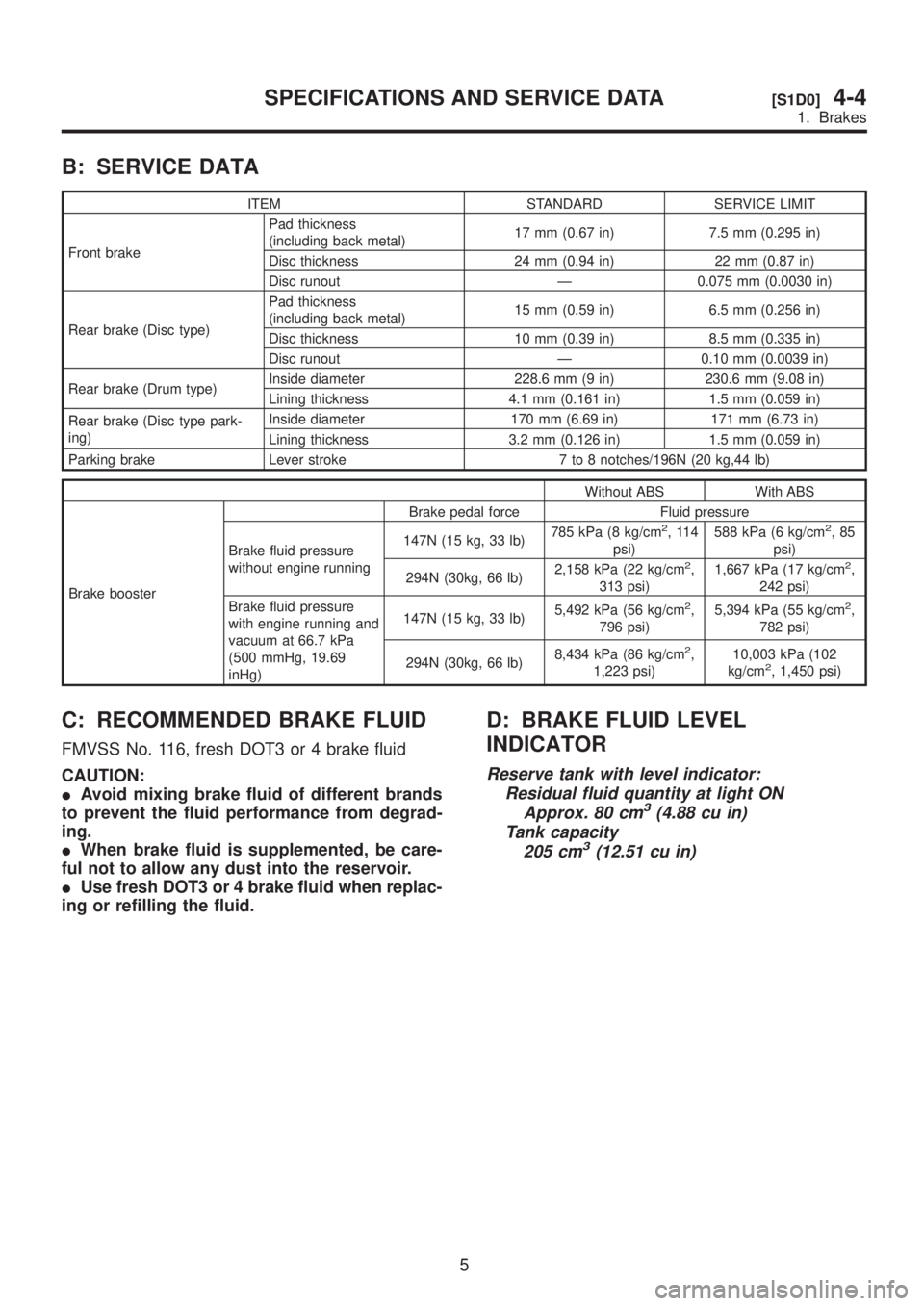
B: SERVICE DATA
ITEM STANDARD SERVICE LIMIT
Front brakePad thickness
(including back metal)17 mm (0.67 in) 7.5 mm (0.295 in)
Disc thickness 24 mm (0.94 in) 22 mm (0.87 in)
Disc runout Ð 0.075 mm (0.0030 in)
Rear brake (Disc type)Pad thickness
(including back metal)15 mm (0.59 in) 6.5 mm (0.256 in)
Disc thickness 10 mm (0.39 in) 8.5 mm (0.335 in)
Disc runout Ð 0.10 mm (0.0039 in)
Rear brake (Drum type)Inside diameter 228.6 mm (9 in) 230.6 mm (9.08 in)
Lining thickness 4.1 mm (0.161 in) 1.5 mm (0.059 in)
Rear brake (Disc type park-
ing)Inside diameter 170 mm (6.69 in) 171 mm (6.73 in)
Lining thickness 3.2 mm (0.126 in) 1.5 mm (0.059 in)
Parking brake Lever stroke 7 to 8 notches/196N (20 kg,44 lb)
Without ABS With ABS
Brake boosterBrake pedal force Fluid pressure
Brake fluid pressure
without engine running147N (15 kg, 33 lb)785 kPa (8 kg/cm
2,114
psi)588 kPa (6 kg/cm2,85
psi)
294N (30kg, 66 lb)2,158 kPa (22 kg/cm
2,
313 psi)1,667 kPa (17 kg/cm2,
242 psi)
Brake fluid pressure
with engine running and
vacuum at 66.7 kPa
(500 mmHg, 19.69
inHg)147N (15 kg, 33 lb)5,492 kPa (56 kg/cm
2,
796 psi)5,394 kPa (55 kg/cm2,
782 psi)
294N (30kg, 66 lb)8,434 kPa (86 kg/cm
2,
1,223 psi)10,003 kPa (102
kg/cm2, 1,450 psi)
C: RECOMMENDED BRAKE FLUID
FMVSS No. 116, fresh DOT3 or 4 brake fluid
CAUTION:
IAvoid mixing brake fluid of different brands
to prevent the fluid performance from degrad-
ing.
IWhen brake fluid is supplemented, be care-
ful not to allow any dust into the reservoir.
IUse fresh DOT3 or 4 brake fluid when replac-
ing or refilling the fluid.
D: BRAKE FLUID LEVEL
INDICATOR
Reserve tank with level indicator:
Residual fluid quantity at light ON
Approx. 80 cm
3(4.88 cu in)
Tank capacity
205 cm
3(12.51 cu in)
5
[S1D0]4-4SPECIFICATIONS AND SERVICE DATA
1. Brakes
Page 914 of 1456

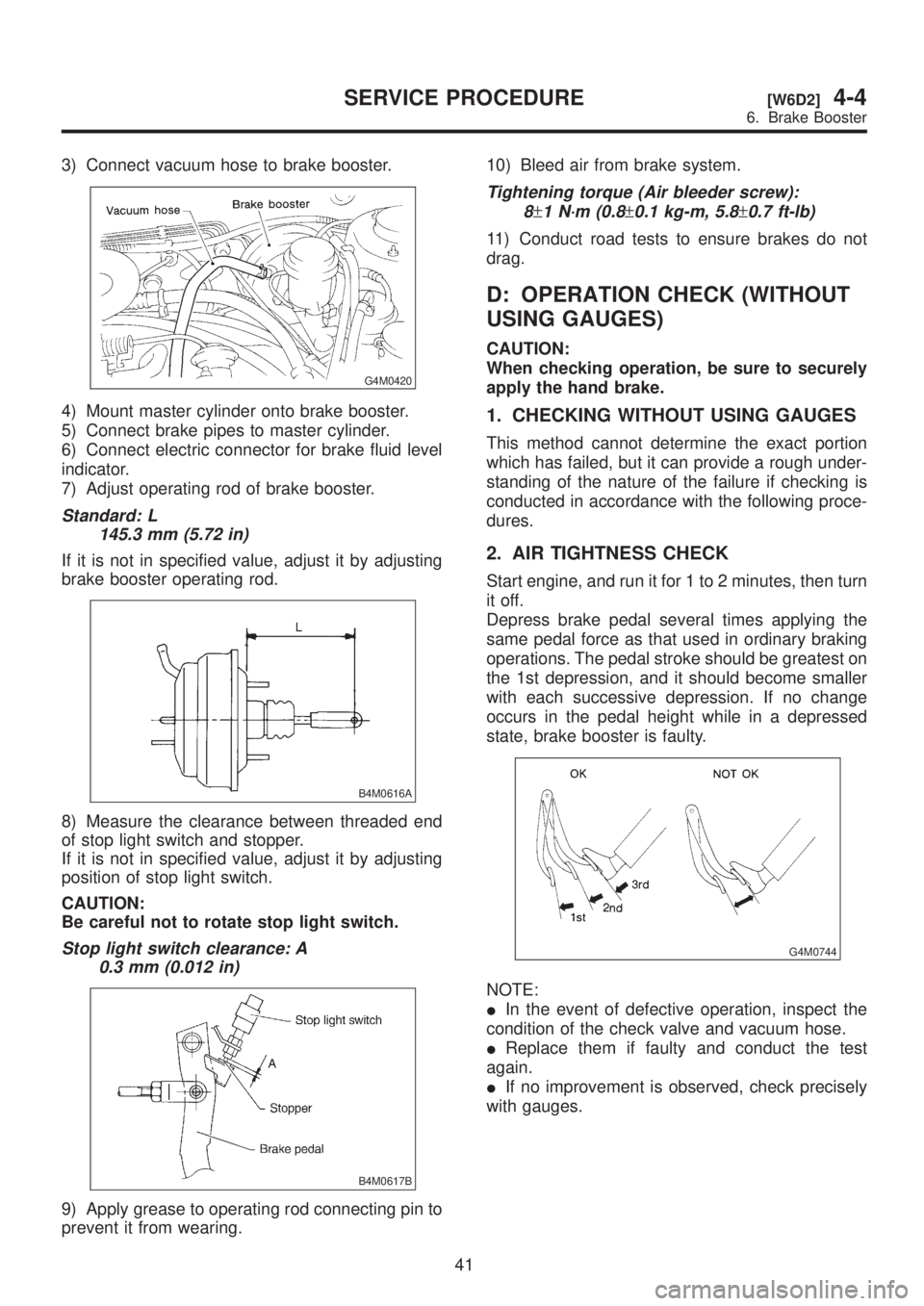
3) Connect vacuum hose to brake booster.
G4M0420
4) Mount master cylinder onto brake booster.
5) Connect brake pipes to master cylinder.
6) Connect electric connector for brake fluid level
indicator.
7) Adjust operating rod of brake booster.
Standard: L
145.3 mm (5.72 in)
If it is not in specified value, adjust it by adjusting
brake booster operating rod.
B4M0616A
8) Measure the clearance between threaded end
of stop light switch and stopper.
If it is not in specified value, adjust it by adjusting
position of stop light switch.
CAUTION:
Be careful not to rotate stop light switch.
Stop light switch clearance: A
0.3 mm (0.012 in)
B4M0617B
9) Apply grease to operating rod connecting pin to
prevent it from wearing.10) Bleed air from brake system.
Tightening torque (Air bleeder screw):
8
±1 N´m (0.8±0.1 kg-m, 5.8±0.7 ft-lb)
11) Conduct road tests to ensure brakes do not
drag.
D: OPERATION CHECK (WITHOUT
USING GAUGES)
CAUTION:
When checking operation, be sure to securely
apply the hand brake.
1. CHECKING WITHOUT USING GAUGES
This method cannot determine the exact portion
which has failed, but it can provide a rough under-
standing of the nature of the failure if checking is
conducted in accordance with the following proce-
dures.
2. AIR TIGHTNESS CHECK
Start engine, and run it for 1 to 2 minutes, then turn
it off.
Depress brake pedal several times applying the
same pedal force as that used in ordinary braking
operations. The pedal stroke should be greatest on
the 1st depression, and it should become smaller
with each successive depression. If no change
occurs in the pedal height while in a depressed
state, brake booster is faulty.
G4M0744
NOTE:
IIn the event of defective operation, inspect the
condition of the check valve and vacuum hose.
IReplace them if faulty and conduct the test
again.
IIf no improvement is observed, check precisely
with gauges.
41
[W6D2]4-4SERVICE PROCEDURE
6. Brake Booster