1999 SUBARU LEGACY manual transmission
[x] Cancel search: manual transmissionPage 465 of 1456

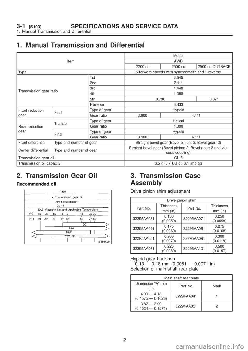
1. Manual Transmission and Differential
ItemModel
AWD
2200 cc 2500 cc 2500 cc OUTBACK
Type 5-forward speeds with synchromesh and 1-reverse
Transmission gear ratio1st 3.545
2nd 2.111
3rd 1.448
4th 1.088
5th 0.780 0.871
Reverse 3.333
Front reduction
gearFinalType of gear Hypoid
Gear ratio 3.900 4.111
Rear reduction
gearTransferType of gear Helical
Gear ratio 1.000
FinalType of gear Hypoid
Gear ratio 3.900 4.111
Front differential Type and number of gear Straight bevel gear (Bevel pinion: 2, Bevel gear: 2)
Center differential Type and number of gearStraight bevel gear (Bevel pinion: 2, Bevel gear: 2 and vis-
cous coupling)
Transmission gear oilGL-5
Transmission oil capacity 3.5(3.7 US qt, 3.1 Imp qt)
2. Transmission Gear Oil
Recommended oil
B1H0024
3. Transmission Case
Assembly
Drive pinion shim adjustment
Drive pinion shim
Part No.Thickness
mm (in)Part No.Thickness
mm (in)
32295AA0310.150
(0.0059)32295AA0710.250
(0.0098)
32295AA0410.175
(0.0069)32295AA0810.275
(0.0108)
32295AA0510.200
(0.0079)32295AA0910.300
(0.0118)
32295AA0610.225
(0.0089)32295AA1010.500
(0.0197)
Hypoid gear backlash
0.13 Ð 0.18 mm (0.0051 Ð 0.0071 in)
Selection of main shaft rear plate
Main shaft rear plate
Dimension ªAº mm
(in)Part No. Mark
4.00 Ð 4.13
(0.1575 Ð 0.1626)32294AA041 1
3.87 Ð 3.99
(0.1524 Ð 0.1571)32294AA051 2
2
3-1[S100]SPECIFICATIONS AND SERVICE DATA
1. Manual Transmission and Differential
Page 466 of 1456

1. Manual Transmission and Differential
ItemModel
AWD
2200 cc 2500 cc 2500 cc OUTBACK
Type 5-forward speeds with synchromesh and 1-reverse
Transmission gear ratio1st 3.545
2nd 2.111
3rd 1.448
4th 1.088
5th 0.780 0.871
Reverse 3.333
Front reduction
gearFinalType of gear Hypoid
Gear ratio 3.900 4.111
Rear reduction
gearTransferType of gear Helical
Gear ratio 1.000
FinalType of gear Hypoid
Gear ratio 3.900 4.111
Front differential Type and number of gear Straight bevel gear (Bevel pinion: 2, Bevel gear: 2)
Center differential Type and number of gearStraight bevel gear (Bevel pinion: 2, Bevel gear: 2 and vis-
cous coupling)
Transmission gear oilGL-5
Transmission oil capacity 3.5(3.7 US qt, 3.1 Imp qt)
2. Transmission Gear Oil
Recommended oil
B1H0024
3. Transmission Case
Assembly
Drive pinion shim adjustment
Drive pinion shim
Part No.Thickness
mm (in)Part No.Thickness
mm (in)
32295AA0310.150
(0.0059)32295AA0710.250
(0.0098)
32295AA0410.175
(0.0069)32295AA0810.275
(0.0108)
32295AA0510.200
(0.0079)32295AA0910.300
(0.0118)
32295AA0610.225
(0.0089)32295AA1010.500
(0.0197)
Hypoid gear backlash
0.13 Ð 0.18 mm (0.0051 Ð 0.0071 in)
Selection of main shaft rear plate
Main shaft rear plate
Dimension ªAº mm
(in)Part No. Mark
4.00 Ð 4.13
(0.1575 Ð 0.1626)32294AA041 1
3.87 Ð 3.99
(0.1524 Ð 0.1571)32294AA051 2
2
3-1[S100]SPECIFICATIONS AND SERVICE DATA
1. Manual Transmission and Differential
Page 467 of 1456

1. Manual Transmission and Differential
ItemModel
AWD
2200 cc 2500 cc 2500 cc OUTBACK
Type 5-forward speeds with synchromesh and 1-reverse
Transmission gear ratio1st 3.545
2nd 2.111
3rd 1.448
4th 1.088
5th 0.780 0.871
Reverse 3.333
Front reduction
gearFinalType of gear Hypoid
Gear ratio 3.900 4.111
Rear reduction
gearTransferType of gear Helical
Gear ratio 1.000
FinalType of gear Hypoid
Gear ratio 3.900 4.111
Front differential Type and number of gear Straight bevel gear (Bevel pinion: 2, Bevel gear: 2)
Center differential Type and number of gearStraight bevel gear (Bevel pinion: 2, Bevel gear: 2 and vis-
cous coupling)
Transmission gear oilGL-5
Transmission oil capacity 3.5(3.7 US qt, 3.1 Imp qt)
2. Transmission Gear Oil
Recommended oil
B1H0024
3. Transmission Case
Assembly
Drive pinion shim adjustment
Drive pinion shim
Part No.Thickness
mm (in)Part No.Thickness
mm (in)
32295AA0310.150
(0.0059)32295AA0710.250
(0.0098)
32295AA0410.175
(0.0069)32295AA0810.275
(0.0108)
32295AA0510.200
(0.0079)32295AA0910.300
(0.0118)
32295AA0610.225
(0.0089)32295AA1010.500
(0.0197)
Hypoid gear backlash
0.13 Ð 0.18 mm (0.0051 Ð 0.0071 in)
Selection of main shaft rear plate
Main shaft rear plate
Dimension ªAº mm
(in)Part No. Mark
4.00 Ð 4.13
(0.1575 Ð 0.1626)32294AA041 1
3.87 Ð 3.99
(0.1524 Ð 0.1571)32294AA051 2
2
3-1[S100]SPECIFICATIONS AND SERVICE DATA
1. Manual Transmission and Differential
Page 524 of 1456

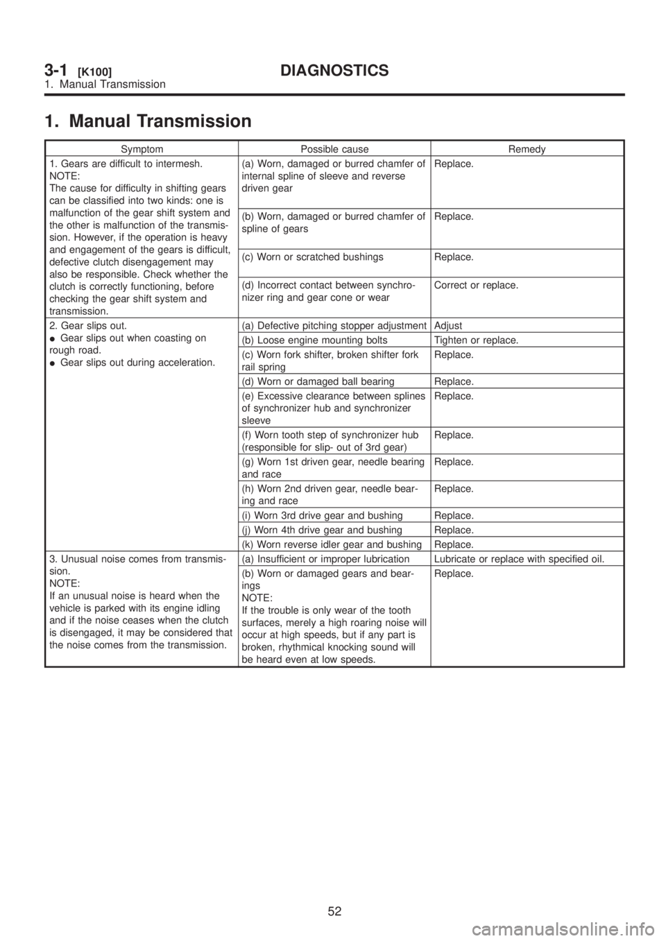
1. Manual Transmission
Symptom Possible cause Remedy
1. Gears are difficult to intermesh.
NOTE:
The cause for difficulty in shifting gears
can be classified into two kinds: one is
malfunction of the gear shift system and
the other is malfunction of the transmis-
sion. However, if the operation is heavy
and engagement of the gears is difficult,
defective clutch disengagement may
also be responsible. Check whether the
clutch is correctly functioning, before
checking the gear shift system and
transmission.(a) Worn, damaged or burred chamfer of
internal spline of sleeve and reverse
driven gearReplace.
(b) Worn, damaged or burred chamfer of
spline of gearsReplace.
(c) Worn or scratched bushings Replace.
(d) Incorrect contact between synchro-
nizer ring and gear cone or wearCorrect or replace.
2. Gear slips out.
IGear slips out when coasting on
rough road.
IGear slips out during acceleration.(a) Defective pitching stopper adjustment Adjust
(b) Loose engine mounting bolts Tighten or replace.
(c) Worn fork shifter, broken shifter fork
rail springReplace.
(d) Worn or damaged ball bearing Replace.
(e) Excessive clearance between splines
of synchronizer hub and synchronizer
sleeveReplace.
(f) Worn tooth step of synchronizer hub
(responsible for slip- out of 3rd gear)Replace.
(g) Worn 1st driven gear, needle bearing
and raceReplace.
(h) Worn 2nd driven gear, needle bear-
ing and raceReplace.
(i) Worn 3rd drive gear and bushing Replace.
(j) Worn 4th drive gear and bushing Replace.
(k) Worn reverse idler gear and bushing Replace.
3. Unusual noise comes from transmis-
sion.
NOTE:
If an unusual noise is heard when the
vehicle is parked with its engine idling
and if the noise ceases when the clutch
is disengaged, it may be considered that
the noise comes from the transmission.(a) Insufficient or improper lubrication Lubricate or replace with specified oil.
(b) Worn or damaged gears and bear-
ings
NOTE:
If the trouble is only wear of the tooth
surfaces, merely a high roaring noise will
occur at high speeds, but if any part is
broken, rhythmical knocking sound will
be heard even at low speeds.Replace.
52
3-1[K100]DIAGNOSTICS
1. Manual Transmission
Page 544 of 1456

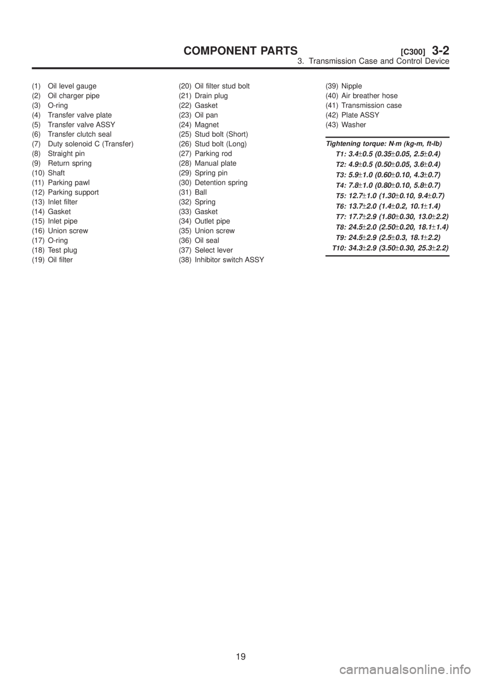
(1) Oil level gauge
(2) Oil charger pipe
(3) O-ring
(4) Transfer valve plate
(5) Transfer valve ASSY
(6) Transfer clutch seal
(7) Duty solenoid C (Transfer)
(8) Straight pin
(9) Return spring
(10) Shaft
(11) Parking pawl
(12) Parking support
(13) Inlet filter
(14) Gasket
(15) Inlet pipe
(16) Union screw
(17) O-ring
(18) Test plug
(19) Oil filter(20) Oil filter stud bolt
(21) Drain plug
(22) Gasket
(23) Oil pan
(24) Magnet
(25) Stud bolt (Short)
(26) Stud bolt (Long)
(27) Parking rod
(28) Manual plate
(29) Spring pin
(30) Detention spring
(31) Ball
(32) Spring
(33) Gasket
(34) Outlet pipe
(35) Union screw
(36) Oil seal
(37) Select lever
(38) Inhibitor switch ASSY(39) Nipple
(40) Air breather hose
(41) Transmission case
(42) Plate ASSY
(43) Washer
Tightening torque: N´m (kg-m, ft-lb)
T1:
3.4±0.5 (0.35±0.05, 2.5±0.4)
T2:4.9±0.5 (0.50±0.05, 3.6±0.4)
T3:5.9±1.0 (0.60±0.10, 4.3±0.7)
T4:7.8±1.0 (0.80±0.10, 5.8±0.7)
T5:12.7±1.0 (1.30±0.10, 9.4±0.7)
T6:13.7±2.0 (1.4±0.2, 10.1±1.4)
T7:17.7±2.9 (1.80±0.30, 13.0±2.2)
T8:24.5±2.0 (2.50±0.20, 18.1±1.4)
T9:24.5±2.9 (2.5±0.3, 18.1±2.2)
T10:34.3±2.9 (3.50±0.30, 25.3±2.2)
19
[C300]3-2COMPONENT PARTS
3. Transmission Case and Control Device
Page 552 of 1456

1. General
A: PRECAUTION
When disassembling or assembling the automatic
transmission, observe the following instructions.
1) Workshop
Provide a place that is clean and free from dust.
Principally the conventional workshop is suitable
except for a dusty place. In a workshop where
grinding work, etc. which produces fine particles is
done, make independent place divided by the vinyl
curtain or the equivalent.
2) Work table
The size of 1 x 1.5 m (40 x 60 in) is large enough
to work, and it is more desirable that its surface be
covered with flat plate like iron plate which is not
rusted too much.
3) Cleaning of exterior
(1) Clean the exterior surface of transmission
with steam and/or kerosene prior to
disassembly, however it should be noted that
vinyl tape be placed on the air breather or oil
level gauge to prevent infiltration of the steam
into the transmission and also the cleaning job
be done away from the place of disassembly
and assembly.
(2) Partial cleaning will do, depending on the
extent of disassembly (such as when disassem-
bly is limited to some certain parts).
4) Disassembly, assembly and cleaning
(1) Disassemble and assemble the transmis-
sion while inspecting the parts in accordance
with the Diagnostics.
(2) During job, do not use gloves. Do not clean
the parts with rags: Use chamois or nylon cloth.
(3) Pay special attention to the air to be used
for cleaning. Get the moisture and the dust rid
of the air as much as possible. Be careful not to
scratch or dent any part while checking for
proper operation with an air gun.
(4) Complete the job from cleaning to comple-
tion of assembly as continuously and speedily
as possible in order to avoid occurrence of sec-
ondary troubles caused by dust. When stopping
the job unavoidably cover the parts with clean
chamois or nylon cloth to keep them away from
any dust.
(5) Use kerosene, white gasoline or the equiva-
lent as washing fluid. Use always new fluid for
cleaning the automatic transmission parts and
never reuse. The used fluid is usable in disas-
semble and assemble work of engine and
manual transmission.
(6) Although the cleaning should be done by
dipping into the washing fluid or blowing of the
pressurized washing fluid, the dipping is more
desirable. (Do not rub with a brush.) Assemblethe parts immediately after the cleaning without
exposure to the air for a while. Besides in case
of washing rubber parts, perform the job quickly
not to dip them into the washing fluid for long
time.
(7) Apply the automatic transmission fluid
(ATF) onto the parts immediately prior to
assembly, and the specified tightening torque
should be observed carefully.
(8) Use vaseline if it is necessary to hold parts
in the position when assembling.
(9) Drain ATF and differential gear oil into a
saucer so that the conditions of fluid and oil can
be inspected.
(10) Do not support axle drive shaft, stator
shaft, input shaft or various pipes when moving
transmission from one place to another.
(11) Always discard old oil seals and O-ring,
and install new ones.
(12) Always discard old oil seals and O-ring,
and install new ones.
(13) Be sure to replace parts which are
damaged, worn, scratched, discolored, etc.
B: INSPECTION
1. ATF LEVEL
1) Raise ATF temperature to 60 to 80ÉC (140 to
176ÉF) from 40 to 60ÉC (104 to 140ÉF) (when cold)
by driving a distance of 5 to 10 km (3 to 6 miles).
NOTE:
The level of ATF varies with fluid temperature. Pay
attention to the fluid temperature when checking oil
level.
B3M1020A
2) Make sure the vehicle is level. After selecting all
positions (P, R, N, D, 3, 2, 1), set the selector lev-
eler in ªPº range. Measure fluid level with the
engine idling.
NOTE:
After running, idle the engine for one or two min-
utes before measurement.
3) If the fluid level is below the center between
upper and lower marks, add the recommended
ATF until the fluid level is found within the specified
27
[W1B1]3-2SERVICE PROCEDURE
1. General
Page 562 of 1456

3) Install valve body to transmission case.
CAUTION:
When installing control valve body, be careful
not to interfere with transfer duty solenoid wir-
ing (brown).
NOTE:
Align manual valve connections.
Tightening torque:
8
±1 N´m (0.8±0.1 kg-m, 5.8±0.7 ft-lb)
B3M1037A
(A) Short bolts
(B) Long bolts
4) Connect harness connectors at 8 places.
Connect connectors of same color, and secure
connectors to valve body using clips.
B2M2263C
(A) Lock-up duty solenoid (Blue)
(B) Low clutch timing solenoid (Gray)
(C) Line pressure duty solenoid (Red)
(D) Shift solenoid 2 (Yellow)
(E) Shift solenoid 1 (Green)
(F) 2-4 brake timing solenoid (Black)
(G) 2-4 brake duty solenoid (Red)
(H) ATF temperature sensor
5) Apply proper amount of liquid gasket (THREE
BOND Part No. 1217B) to the entire oil pan mat-
ing surface.
B3M1040A
6) Install oil pan.
Tightening torque:
4.9
±0.5 N´m (0.50±0.05 kg-m, 3.6±0.4 ft-lb)
B3M1036A
7) Add ATF and check level.
B3M1020A
36
3-2[W4B0]SERVICE PROCEDURE
4. Shift Solenoid, Duty Solenoid and Valve
Page 570 of 1456

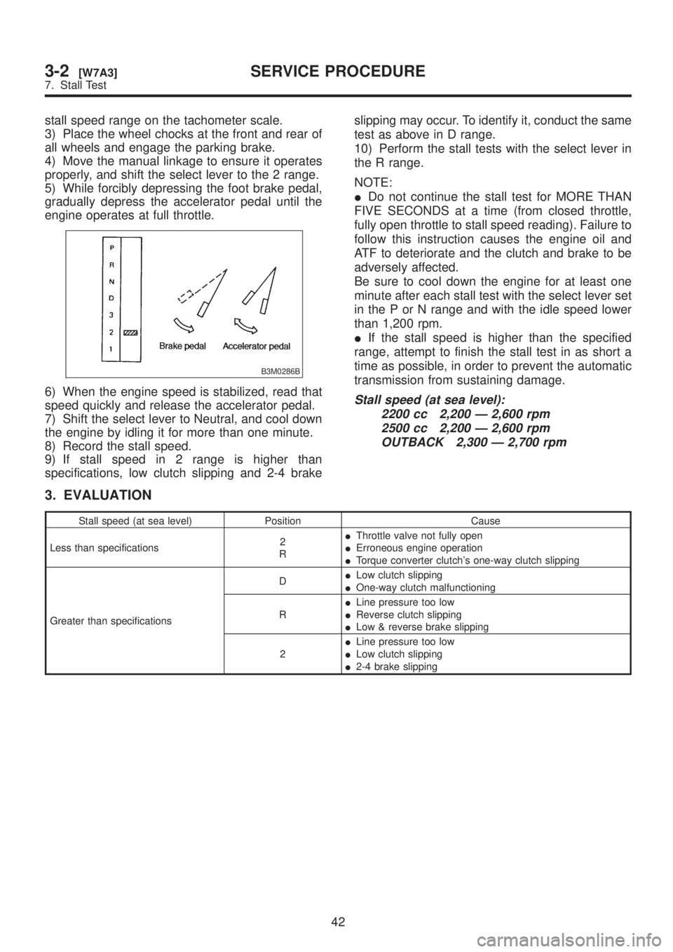
stall speed range on the tachometer scale.
3) Place the wheel chocks at the front and rear of
all wheels and engage the parking brake.
4) Move the manual linkage to ensure it operates
properly, and shift the select lever to the 2 range.
5) While forcibly depressing the foot brake pedal,
gradually depress the accelerator pedal until the
engine operates at full throttle.
B3M0286B
6) When the engine speed is stabilized, read that
speed quickly and release the accelerator pedal.
7) Shift the select lever to Neutral, and cool down
the engine by idling it for more than one minute.
8) Record the stall speed.
9) If stall speed in 2 range is higher than
specifications, low clutch slipping and 2-4 brakeslipping may occur. To identify it, conduct the same
test as above in D range.
10) Perform the stall tests with the select lever in
the R range.
NOTE:
IDo not continue the stall test for MORE THAN
FIVE SECONDS at a time (from closed throttle,
fully open throttle to stall speed reading). Failure to
follow this instruction causes the engine oil and
ATF to deteriorate and the clutch and brake to be
adversely affected.
Be sure to cool down the engine for at least one
minute after each stall test with the select lever set
in the P or N range and with the idle speed lower
than 1,200 rpm.
IIf the stall speed is higher than the specified
range, attempt to finish the stall test in as short a
time as possible, in order to prevent the automatic
transmission from sustaining damage.Stall speed (at sea level):
2200 cc 2,200 Ð 2,600 rpm
2500 cc 2,200 Ð 2,600 rpm
OUTBACK 2,300 Ð 2,700 rpm
3. EVALUATION
Stall speed (at sea level) Position Cause
Less than specifications2
RIThrottle valve not fully open
IErroneous engine operation
ITorque converter clutch's one-way clutch slipping
Greater than specificationsDILow clutch slipping
IOne-way clutch malfunctioning
RILine pressure too low
IReverse clutch slipping
ILow & reverse brake slipping
2ILine pressure too low
ILow clutch slipping
I2-4 brake slipping
42
3-2[W7A3]SERVICE PROCEDURE
7. Stall Test