Page 35 of 1456

3. Engine Idle Speed
A: MEASUREMENT
1) Before checking idle speed, check the follow-
ing:
(1) Ensure that air cleaner element is free from
clogging, ignition timing is correct, spark plugs
are in good condition, and that hoses are con-
nected properly.
(2) Ensure that malfunction indicator light
(CHECK ENGINE light) does not illuminate.
2) Warm-up the engine.
3) Stop the engine, and turn ignition switch to
OFF.
4) When using SUBARU SELECT MONITOR;
NOTE:
For detailed operation procedures, refer to the
SUBARU SELECT MONITOR OPERATION
MANUAL.
(1) Insert the cartridge to SUBARU SELECT
MONITOR.
ST 24082AA090 CARTRIDGE
S2M0286A
(2) Connect SUBARU SELECT MONITOR to
the data link connector.
(3) Turn ignition switch to ON, and SUBARU
SELECT MONITOR switch to ON.
(4) Select {2. Each System Check} in Main
Menu.
(5) Select {EGI/EMPI} in Selection Menu.
(6) Select {1. Current Data Display & Save} in
EGI/EMPI Diagnosis.
(7) Select {1.12 Data Display} in Data Display
Menu.(8) Start the engine, and read engine idle
speed.
S2M0098
5) When using tachometer (Secondary pick-up
type).
(1) Attach the pick-up clip to No. 1 cylinder
spark plug cord.
(2) Start the engine, and read engine idle
speed.
B2M2011
NOTE:
IWhen using the OBD-II general scan tool, care-
fully read its operation manual.
IThis ignition system provides simultaneous igni-
tion for #1 and #2 plugs. It must be noted that
some tachometers may register twice that of actual
engine speed.
6) Check idle speed when unloaded. (With
headlights, heater fan, rear defroster, radiator fan,
air conditioning, etc. OFF)
Idle speed (No load and gears in neutral (MT),
or N or P (AT) position):
700
±100 rpm
7) Check idle speed when loaded. (Turn air con-
ditioning switch to |P¢rdquo;ON|P'ldquo; and oper-
ate compressor for at least one minute before
measurement.)
Idle speed [A/C ªONº, no load and gears in
neutral (MT) or N or P (AT) position]:
850
±50 rpm
3
[W3A0]2-2SERVICE PROCEDURE
3. Engine Idle Speed
Page 212 of 1456
1. Oil Pump
A: REMOVAL
1) Disconnect battery ground cable.
G6M0095
2) Lift-up the vehicle.
3) Remove under cover.
B2M0014
4) Drain coolant.
B2M0015A
5) Remove radiator.
S2M0033
6) Lower the vehicle.
7) Remove crankshaft position sensor.
B2M1252A
8) Remove camshaft position sensor.
G2M0417
9) Remove V-belts.
G2M0286
10) Remove rear side V-belt tensioner.
S2M0113
6
2-4[W1A0]SERVICE PROCEDURE
1. Oil Pump
Page 218 of 1456
5) Disconnect front oxygen sensor connector.
B2M1979A
S2M0127A
6) Disconnect rear oxygen sensor connector.
(2500 cc California spec. vehicles)
S2M0128
7) Remove pitching stopper.
G2M0295
8) Remove radiator upper bracket.
B2M0320
9) Support engine with a lifting device and wire
ropes.
B2M0053
10) Lift-up the vehicle.
CAUTION:
At this time, raise up wire ropes.
11) Remove under cover.
B2M0014
11
[W2A0]2-4SERVICE PROCEDURE
2. Oil Pan and Oil Strainer
Page 223 of 1456
15) Install radiator upper brackets.
Tightening torque:
18
±5 N´m (1.8±0.5 kg-m, 13±4 ft-lb)
B2M0320
16) Install air intake duct and air cleaner assem-
bly. (2200 cc California spec. vehicles)
B2M2771
17) Install air intake duct and air intake chamber.
(Except 2200 cc California spec. vehicles)
B2M2772
18) Fill engine oil through filler pipe up to upper
point of level gauge.
Engine oil capacity:
2200 cc ; Upper level
4.0
(4.2 US qt, 3.5 Imp qt)
2200 cc ; Lower level
3.0
(3.2 US qt, 2.6 Imp qt)
2500 cc ; Upper level
4.5
(4.8 US qt, 4.0 Imp qt)
2500 cc ; Lower level
3.5
(3.7 US qt, 3.1 Imp qt)
3. Oil Pressure Switch
A: REMOVAL
1) Remove alternator from bracket.
(1) Disconnect connector and terminal from
generator.
H6M0402
(2) Remove V-belt cover.
B2M0017
(3) Loosen lock bolt and slider bolt, and remove
front side V-belt.
(4) Remove bolts which install generator on
bracket.
H2M1499
16
2-4[W3A0]SERVICE PROCEDURE
3. Oil Pressure Switch
Page 224 of 1456
15) Install radiator upper brackets.
Tightening torque:
18
±5 N´m (1.8±0.5 kg-m, 13±4 ft-lb)
B2M0320
16) Install air intake duct and air cleaner assem-
bly. (2200 cc California spec. vehicles)
B2M2771
17) Install air intake duct and air intake chamber.
(Except 2200 cc California spec. vehicles)
B2M2772
18) Fill engine oil through filler pipe up to upper
point of level gauge.
Engine oil capacity:
2200 cc ; Upper level
4.0
(4.2 US qt, 3.5 Imp qt)
2200 cc ; Lower level
3.0
(3.2 US qt, 2.6 Imp qt)
2500 cc ; Upper level
4.5
(4.8 US qt, 4.0 Imp qt)
2500 cc ; Lower level
3.5
(3.7 US qt, 3.1 Imp qt)
3. Oil Pressure Switch
A: REMOVAL
1) Remove alternator from bracket.
(1) Disconnect connector and terminal from
generator.
H6M0402
(2) Remove V-belt cover.
B2M0017
(3) Loosen lock bolt and slider bolt, and remove
front side V-belt.
(4) Remove bolts which install generator on
bracket.
H2M1499
16
2-4[W3A0]SERVICE PROCEDURE
3. Oil Pressure Switch
Page 229 of 1456

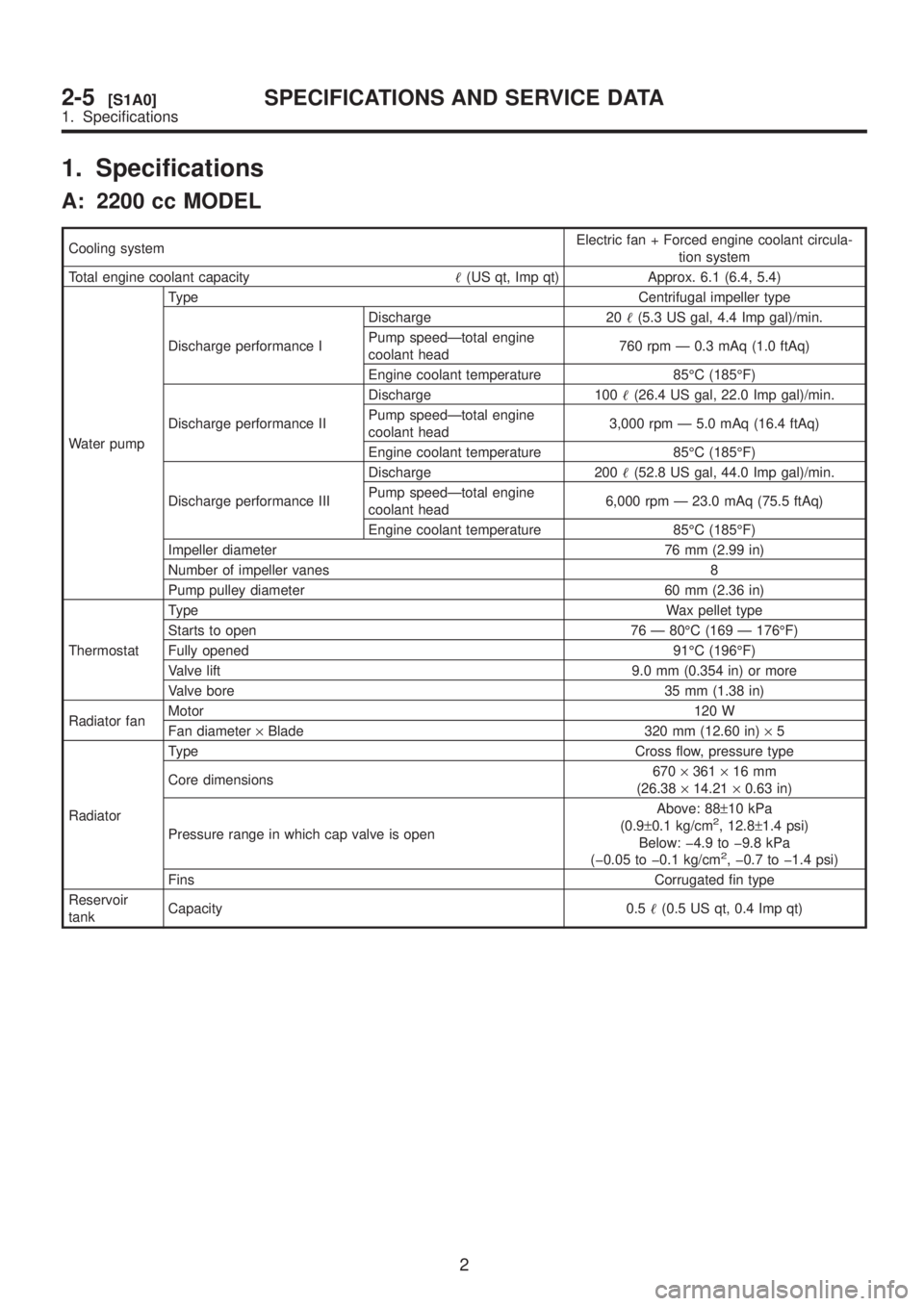
1. Specifications
A: 2200 cc MODEL
Cooling systemElectric fan + Forced engine coolant circula-
tion system
Total engine coolant capacity(US qt, Imp qt) Approx. 6.1 (6.4, 5.4)
Water pumpType Centrifugal impeller type
Discharge performance IDischarge 20(5.3 US gal, 4.4 Imp gal)/min.
Pump speedÐtotal engine
coolant head760 rpm Ð 0.3 mAq (1.0 ftAq)
Engine coolant temperature 85ÉC (185ÉF)
Discharge performance IIDischarge 100(26.4 US gal, 22.0 Imp gal)/min.
Pump speedÐtotal engine
coolant head3,000 rpm Ð 5.0 mAq (16.4 ftAq)
Engine coolant temperature 85ÉC (185ÉF)
Discharge performance IIIDischarge 200(52.8 US gal, 44.0 Imp gal)/min.
Pump speedÐtotal engine
coolant head6,000 rpm Ð 23.0 mAq (75.5 ftAq)
Engine coolant temperature 85ÉC (185ÉF)
Impeller diameter 76 mm (2.99 in)
Number of impeller vanes 8
Pump pulley diameter 60 mm (2.36 in)
ThermostatTypeWax pellet type
Starts to open 76 Ð 80ÉC (169 Ð 176ÉF)
Fully opened 91ÉC (196ÉF)
Valve lift 9.0 mm (0.354 in) or more
Valve bore 35 mm (1.38 in)
Radiator fanMotor120 W
Fan diameter´Blade 320 mm (12.60 in)´5
RadiatorType Cross flow, pressure type
Core dimensions670´361´16 mm
(26.38´14.21´0.63 in)
Pressure range in which cap valve is openAbove: 88±10 kPa
(0.9±0.1 kg/cm
2, 12.8±1.4 psi)
Below: þ4.9 to þ9.8 kPa
(þ0.05 to þ0.1 kg/cm
2, þ0.7 to þ1.4 psi)
FinsCorrugated fin type
Reservoir
tankCapacity 0.5(0.5 US qt, 0.4 Imp qt)
2
2-5[S1A0]SPECIFICATIONS AND SERVICE DATA
1. Specifications
Page 230 of 1456

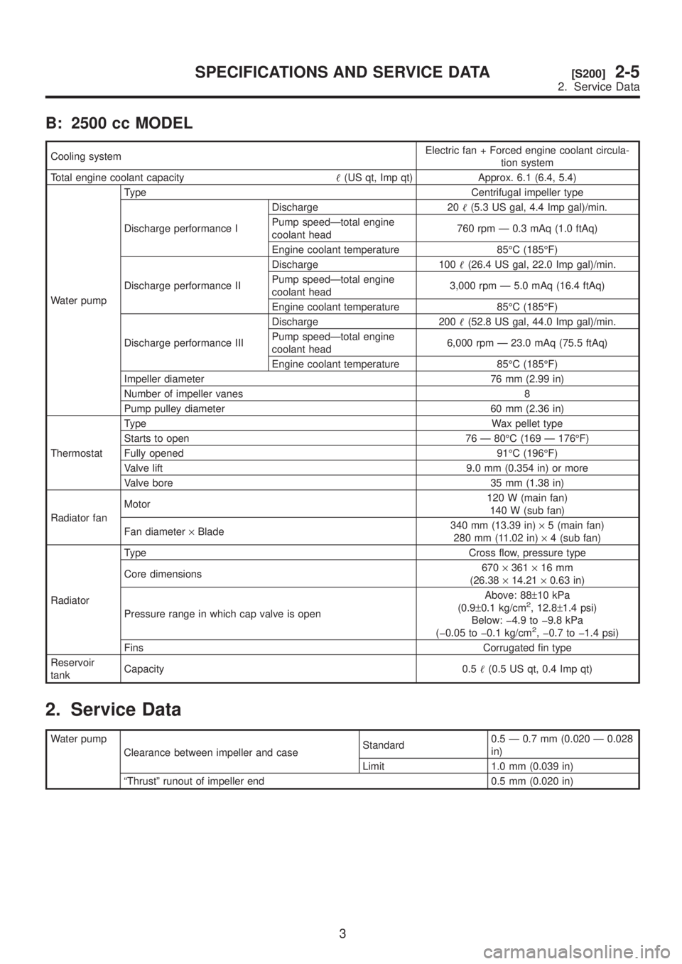
B: 2500 cc MODEL
Cooling systemElectric fan + Forced engine coolant circula-
tion system
Total engine coolant capacity(US qt, Imp qt) Approx. 6.1 (6.4, 5.4)
Water pumpType Centrifugal impeller type
Discharge performance IDischarge 20(5.3 US gal, 4.4 Imp gal)/min.
Pump speedÐtotal engine
coolant head760 rpm Ð 0.3 mAq (1.0 ftAq)
Engine coolant temperature 85ÉC (185ÉF)
Discharge performance IIDischarge 100(26.4 US gal, 22.0 Imp gal)/min.
Pump speedÐtotal engine
coolant head3,000 rpm Ð 5.0 mAq (16.4 ftAq)
Engine coolant temperature 85ÉC (185ÉF)
Discharge performance IIIDischarge 200(52.8 US gal, 44.0 Imp gal)/min.
Pump speedÐtotal engine
coolant head6,000 rpm Ð 23.0 mAq (75.5 ftAq)
Engine coolant temperature 85ÉC (185ÉF)
Impeller diameter 76 mm (2.99 in)
Number of impeller vanes 8
Pump pulley diameter 60 mm (2.36 in)
ThermostatTypeWax pellet type
Starts to open 76 Ð 80ÉC (169 Ð 176ÉF)
Fully opened 91ÉC (196ÉF)
Valve lift 9.0 mm (0.354 in) or more
Valve bore 35 mm (1.38 in)
Radiator fanMotor120 W (main fan)
140 W (sub fan)
Fan diameter´Blade340 mm (13.39 in)´5 (main fan)
280 mm (11.02 in)´4 (sub fan)
RadiatorType Cross flow, pressure type
Core dimensions670´361´16 mm
(26.38´14.21´0.63 in)
Pressure range in which cap valve is openAbove: 88±10 kPa
(0.9±0.1 kg/cm
2, 12.8±1.4 psi)
Below: þ4.9 to þ9.8 kPa
(þ0.05 to þ0.1 kg/cm
2, þ0.7 to þ1.4 psi)
FinsCorrugated fin type
Reservoir
tankCapacity 0.5(0.5 US qt, 0.4 Imp qt)
2. Service Data
Water pump
Clearance between impeller and caseStandard0.5 Ð 0.7 mm (0.020 Ð 0.028
in)
Limit 1.0 mm (0.039 in)
ªThrustº runout of impeller end 0.5 mm (0.020 in)
3
[S200]2-5SPECIFICATIONS AND SERVICE DATA
2. Service Data
Page 231 of 1456

B: 2500 cc MODEL
Cooling systemElectric fan + Forced engine coolant circula-
tion system
Total engine coolant capacity(US qt, Imp qt) Approx. 6.1 (6.4, 5.4)
Water pumpType Centrifugal impeller type
Discharge performance IDischarge 20(5.3 US gal, 4.4 Imp gal)/min.
Pump speedÐtotal engine
coolant head760 rpm Ð 0.3 mAq (1.0 ftAq)
Engine coolant temperature 85ÉC (185ÉF)
Discharge performance IIDischarge 100(26.4 US gal, 22.0 Imp gal)/min.
Pump speedÐtotal engine
coolant head3,000 rpm Ð 5.0 mAq (16.4 ftAq)
Engine coolant temperature 85ÉC (185ÉF)
Discharge performance IIIDischarge 200(52.8 US gal, 44.0 Imp gal)/min.
Pump speedÐtotal engine
coolant head6,000 rpm Ð 23.0 mAq (75.5 ftAq)
Engine coolant temperature 85ÉC (185ÉF)
Impeller diameter 76 mm (2.99 in)
Number of impeller vanes 8
Pump pulley diameter 60 mm (2.36 in)
ThermostatTypeWax pellet type
Starts to open 76 Ð 80ÉC (169 Ð 176ÉF)
Fully opened 91ÉC (196ÉF)
Valve lift 9.0 mm (0.354 in) or more
Valve bore 35 mm (1.38 in)
Radiator fanMotor120 W (main fan)
140 W (sub fan)
Fan diameter´Blade340 mm (13.39 in)´5 (main fan)
280 mm (11.02 in)´4 (sub fan)
RadiatorType Cross flow, pressure type
Core dimensions670´361´16 mm
(26.38´14.21´0.63 in)
Pressure range in which cap valve is openAbove: 88±10 kPa
(0.9±0.1 kg/cm
2, 12.8±1.4 psi)
Below: þ4.9 to þ9.8 kPa
(þ0.05 to þ0.1 kg/cm
2, þ0.7 to þ1.4 psi)
FinsCorrugated fin type
Reservoir
tankCapacity 0.5(0.5 US qt, 0.4 Imp qt)
2. Service Data
Water pump
Clearance between impeller and caseStandard0.5 Ð 0.7 mm (0.020 Ð 0.028
in)
Limit 1.0 mm (0.039 in)
ªThrustº runout of impeller end 0.5 mm (0.020 in)
3
[S200]2-5SPECIFICATIONS AND SERVICE DATA
2. Service Data