1999 SUBARU LEGACY brakes
[x] Cancel search: brakesPage 415 of 1456
1. General
A: PRECAUTION
When servicing clutch system, pay attention to the
following items.
1. MECHANICAL APPLICATION TYPE
1) Check the routing of clutch cable for smooth-
ness.
2) Excessive tightness or looseness of clutch
cable have a bad influence upon the cable durabil-
ity.
3) Apply grease sufficiently to the connecting por-
tion of clutch pedal.
4) Apply grease sufficiently to the release lever
portion.
5) Position clutch cable through the center of toe
board hole and route it smoothly. Adjustment is
done by moving the outer cable.
6) Make sure not to let the clutch chatter when
starting forward or rearward. If clutch chattering
occurs, readjust so that the bend of clutch outer
cable becomes flatter.
2. HYDRAULIC APPLICATION TYPE
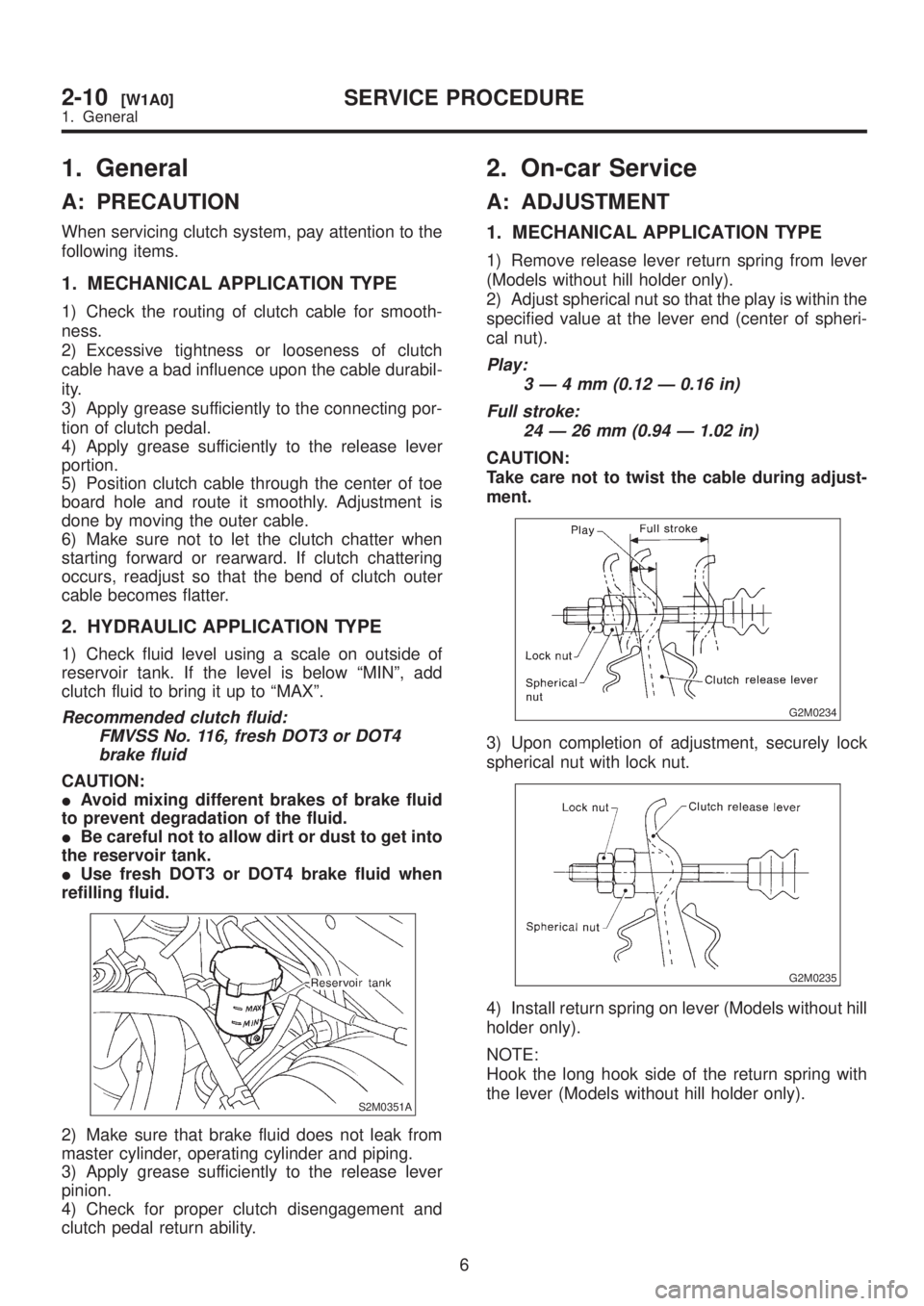
1) Check fluid level using a scale on outside of
reservoir tank. If the level is below ªMINº, add
clutch fluid to bring it up to ªMAXº.
Recommended clutch fluid:
FMVSS No. 116, fresh DOT3 or DOT4
brake fluid
CAUTION:
IAvoid mixing different brakes of brake fluid
to prevent degradation of the fluid.
IBe careful not to allow dirt or dust to get into
the reservoir tank.
IUse fresh DOT3 or DOT4 brake fluid when
refilling fluid.
S2M0351A
2) Make sure that brake fluid does not leak from
master cylinder, operating cylinder and piping.
3) Apply grease sufficiently to the release lever
pinion.
4) Check for proper clutch disengagement and
clutch pedal return ability.
2. On-car Service
A: ADJUSTMENT
1. MECHANICAL APPLICATION TYPE
1) Remove release lever return spring from lever
(Models without hill holder only).
2) Adjust spherical nut so that the play is within the
specified value at the lever end (center of spheri-
cal nut).
Play:
3Ð4mm(0.12 Ð 0.16 in)
Full stroke:
24 Ð 26 mm (0.94 Ð 1.02 in)
CAUTION:
Take care not to twist the cable during adjust-
ment.
G2M0234
3) Upon completion of adjustment, securely lock
spherical nut with lock nut.
G2M0235
4) Install return spring on lever (Models without hill
holder only).
NOTE:
Hook the long hook side of the return spring with
the lever (Models without hill holder only).
6
2-10[W1A0]SERVICE PROCEDURE
1. General
Page 416 of 1456
1. General
A: PRECAUTION
When servicing clutch system, pay attention to the
following items.
1. MECHANICAL APPLICATION TYPE
1) Check the routing of clutch cable for smooth-
ness.
2) Excessive tightness or looseness of clutch
cable have a bad influence upon the cable durabil-
ity.
3) Apply grease sufficiently to the connecting por-
tion of clutch pedal.
4) Apply grease sufficiently to the release lever
portion.
5) Position clutch cable through the center of toe
board hole and route it smoothly. Adjustment is
done by moving the outer cable.
6) Make sure not to let the clutch chatter when
starting forward or rearward. If clutch chattering
occurs, readjust so that the bend of clutch outer
cable becomes flatter.
2. HYDRAULIC APPLICATION TYPE
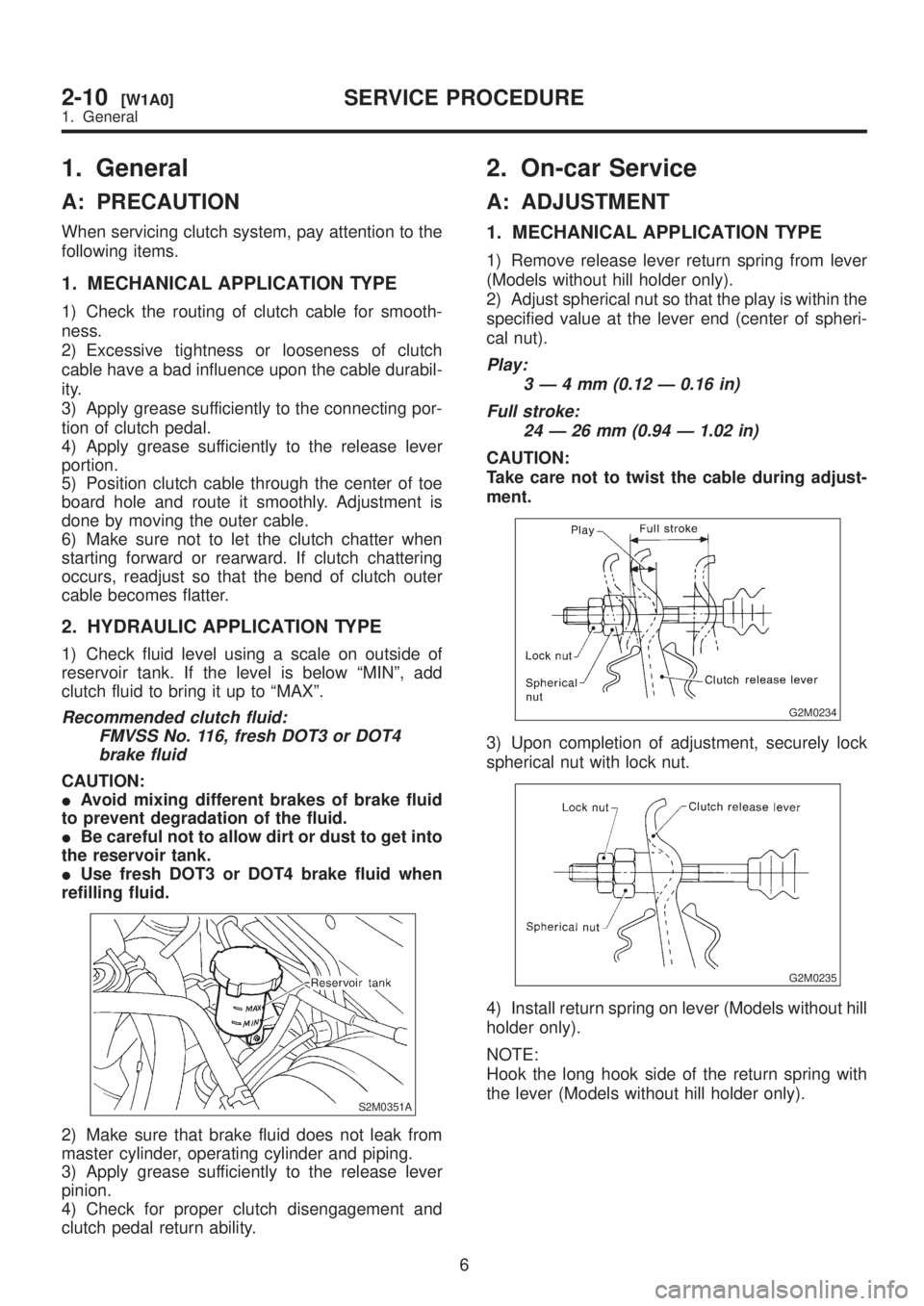
1) Check fluid level using a scale on outside of
reservoir tank. If the level is below ªMINº, add
clutch fluid to bring it up to ªMAXº.
Recommended clutch fluid:
FMVSS No. 116, fresh DOT3 or DOT4
brake fluid
CAUTION:
IAvoid mixing different brakes of brake fluid
to prevent degradation of the fluid.
IBe careful not to allow dirt or dust to get into
the reservoir tank.
IUse fresh DOT3 or DOT4 brake fluid when
refilling fluid.
S2M0351A
2) Make sure that brake fluid does not leak from
master cylinder, operating cylinder and piping.
3) Apply grease sufficiently to the release lever
pinion.
4) Check for proper clutch disengagement and
clutch pedal return ability.
2. On-car Service
A: ADJUSTMENT
1. MECHANICAL APPLICATION TYPE
1) Remove release lever return spring from lever
(Models without hill holder only).
2) Adjust spherical nut so that the play is within the
specified value at the lever end (center of spheri-
cal nut).
Play:
3Ð4mm(0.12 Ð 0.16 in)
Full stroke:
24 Ð 26 mm (0.94 Ð 1.02 in)
CAUTION:
Take care not to twist the cable during adjust-
ment.
G2M0234
3) Upon completion of adjustment, securely lock
spherical nut with lock nut.
G2M0235
4) Install return spring on lever (Models without hill
holder only).
NOTE:
Hook the long hook side of the return spring with
the lever (Models without hill holder only).
6
2-10[W1A0]SERVICE PROCEDURE
1. General
Page 570 of 1456
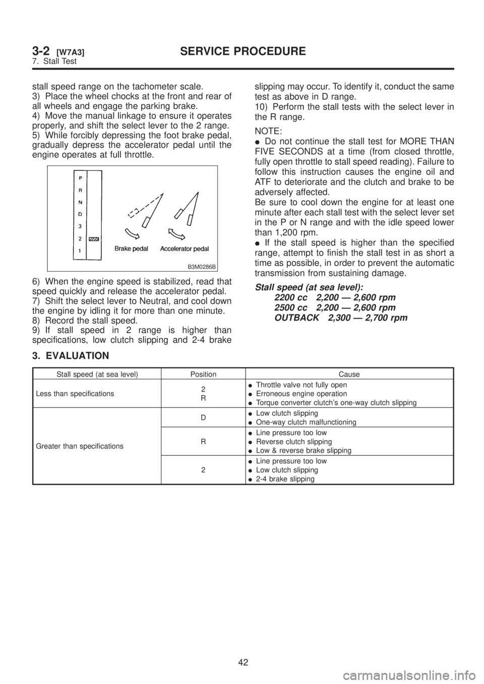
stall speed range on the tachometer scale.
3) Place the wheel chocks at the front and rear of
all wheels and engage the parking brake.
4) Move the manual linkage to ensure it operates
properly, and shift the select lever to the 2 range.
5) While forcibly depressing the foot brake pedal,
gradually depress the accelerator pedal until the
engine operates at full throttle.
B3M0286B
6) When the engine speed is stabilized, read that
speed quickly and release the accelerator pedal.
7) Shift the select lever to Neutral, and cool down
the engine by idling it for more than one minute.
8) Record the stall speed.
9) If stall speed in 2 range is higher than
specifications, low clutch slipping and 2-4 brakeslipping may occur. To identify it, conduct the same
test as above in D range.
10) Perform the stall tests with the select lever in
the R range.
NOTE:
IDo not continue the stall test for MORE THAN
FIVE SECONDS at a time (from closed throttle,
fully open throttle to stall speed reading). Failure to
follow this instruction causes the engine oil and
ATF to deteriorate and the clutch and brake to be
adversely affected.
Be sure to cool down the engine for at least one
minute after each stall test with the select lever set
in the P or N range and with the idle speed lower
than 1,200 rpm.
IIf the stall speed is higher than the specified
range, attempt to finish the stall test in as short a
time as possible, in order to prevent the automatic
transmission from sustaining damage.Stall speed (at sea level):
2200 cc 2,200 Ð 2,600 rpm
2500 cc 2,200 Ð 2,600 rpm
OUTBACK 2,300 Ð 2,700 rpm
3. EVALUATION
Stall speed (at sea level) Position Cause
Less than specifications2
RIThrottle valve not fully open
IErroneous engine operation
ITorque converter clutch's one-way clutch slipping
Greater than specificationsDILow clutch slipping
IOne-way clutch malfunctioning
RILine pressure too low
IReverse clutch slipping
ILow & reverse brake slipping
2ILine pressure too low
ILow clutch slipping
I2-4 brake slipping
42
3-2[W7A3]SERVICE PROCEDURE
7. Stall Test
Page 571 of 1456
8. Time Lag Test
A: INSPECTION
1. GENERAL INFORMATION
If the shift lever is shifted while the engine is idling,
there will be a certain time elapse or lag before the
shock can be felt. This is used for checking the
condition of the low clutch, reverse clutch, low &
reverse brake and one-way clutch.
CAUTION:
IPerform the test at normal operation fluid
temperature 60 to 80ÉC (140 to 176ÉF).
IBe sure to allow a one minute interval
between tests.
IMake three measurements and take the aver-
age value.
2. TEST METHODS
1) Fully apply the parking brake.
2) Start the engine.
Check idling speed (A/C OFF).
ªNº range: 800±100 rpm
3) Shift the shift lever from ªNº to ªDº range.
Using a stop watch, measure the time it takes from
shifting the lever until the shock is felt.
Time lag: Less than 1.2 seconds
4) In same manner, measure the time lag for ªNº
®ªRº.
Time lag: Less than 1.5 seconds
3. EVALUATION
1) If ªNº®ªDº time lag is longer than specified:
ILine pressure too low
ILow clutch worn
IOne-way clutch not operating properly
2) If ªNº®ªRº time lag is longer than specified:
ILine pressure too low
IReverse clutch worn
ILow & reverse brake worn
9. Line Pressure Test
A: MEASUREMENT
1. GENERAL INFORMATION
If the clutch or the brake shows a sign of slippage
or shifting sensation is not correct, the line pres-
sure should be checked.
IExcessive shocks during upshifting or shifting
takes place at a higher point than under normal
circumstances, may be due to the line pressure
being too high.
ISlippage or inability to operate the vehicle may,
in most cases, be due to loss of oil pressure for the
operation of the clutch, brake or control valve.
1) Line pressure measurement (under no load)
CAUTION:
IBefore measuring line pressure, jack-up all
wheels.
IMaintain temperature of ATF at approxi-
mately 50ÉC (122ÉF) during measurement.
(ATF will reach the above temperature after
idling the engine for approximately 30 minutes
with select lever in ªNº or ªPº.)
2) Line pressure measurement (under heavy load)
CAUTION:
IBefore measuring line pressure, apply both
foot and parking brakes with all wheels
chocked (Same as for ªstallº test conditions).
IMeasure line pressure when select lever is in
ªRº, ª2º with engine under stall conditions.
IMeasure line pressure within 5 seconds after
shifting the select lever to each position. (If line
pressure needs to be measured again, allow
the engine to idle and then stop. Wait for at
least one minute before measurement.)
IMaintain the temperature of ATF at approxi-
mately 50ÉC (122ÉF) during measurement. (ATF
will reach the above temperature after idling
the engine for approximately 30 minutes with
the select lever in ªNº or ªPº.)
43
[W9A1]3-2SERVICE PROCEDURE
9. Line Pressure Test
Page 572 of 1456

8. Time Lag Test
A: INSPECTION
1. GENERAL INFORMATION
If the shift lever is shifted while the engine is idling,
there will be a certain time elapse or lag before the
shock can be felt. This is used for checking the
condition of the low clutch, reverse clutch, low &
reverse brake and one-way clutch.
CAUTION:
IPerform the test at normal operation fluid
temperature 60 to 80ÉC (140 to 176ÉF).
IBe sure to allow a one minute interval
between tests.
IMake three measurements and take the aver-
age value.
2. TEST METHODS
1) Fully apply the parking brake.
2) Start the engine.
Check idling speed (A/C OFF).
ªNº range: 800±100 rpm
3) Shift the shift lever from ªNº to ªDº range.
Using a stop watch, measure the time it takes from
shifting the lever until the shock is felt.
Time lag: Less than 1.2 seconds
4) In same manner, measure the time lag for ªNº
®ªRº.
Time lag: Less than 1.5 seconds
3. EVALUATION
1) If ªNº®ªDº time lag is longer than specified:
ILine pressure too low
ILow clutch worn
IOne-way clutch not operating properly
2) If ªNº®ªRº time lag is longer than specified:
ILine pressure too low
IReverse clutch worn
ILow & reverse brake worn
9. Line Pressure Test
A: MEASUREMENT
1. GENERAL INFORMATION
If the clutch or the brake shows a sign of slippage
or shifting sensation is not correct, the line pres-
sure should be checked.
IExcessive shocks during upshifting or shifting
takes place at a higher point than under normal
circumstances, may be due to the line pressure
being too high.
ISlippage or inability to operate the vehicle may,
in most cases, be due to loss of oil pressure for the
operation of the clutch, brake or control valve.
1) Line pressure measurement (under no load)
CAUTION:
IBefore measuring line pressure, jack-up all
wheels.
IMaintain temperature of ATF at approxi-
mately 50ÉC (122ÉF) during measurement.
(ATF will reach the above temperature after
idling the engine for approximately 30 minutes
with select lever in ªNº or ªPº.)
2) Line pressure measurement (under heavy load)
CAUTION:
IBefore measuring line pressure, apply both
foot and parking brakes with all wheels
chocked (Same as for ªstallº test conditions).
IMeasure line pressure when select lever is in
ªRº, ª2º with engine under stall conditions.
IMeasure line pressure within 5 seconds after
shifting the select lever to each position. (If line
pressure needs to be measured again, allow
the engine to idle and then stop. Wait for at
least one minute before measurement.)
IMaintain the temperature of ATF at approxi-
mately 50ÉC (122ÉF) during measurement. (ATF
will reach the above temperature after idling
the engine for approximately 30 minutes with
the select lever in ªNº or ªPº.)
43
[W9A1]3-2SERVICE PROCEDURE
9. Line Pressure Test
Page 582 of 1456
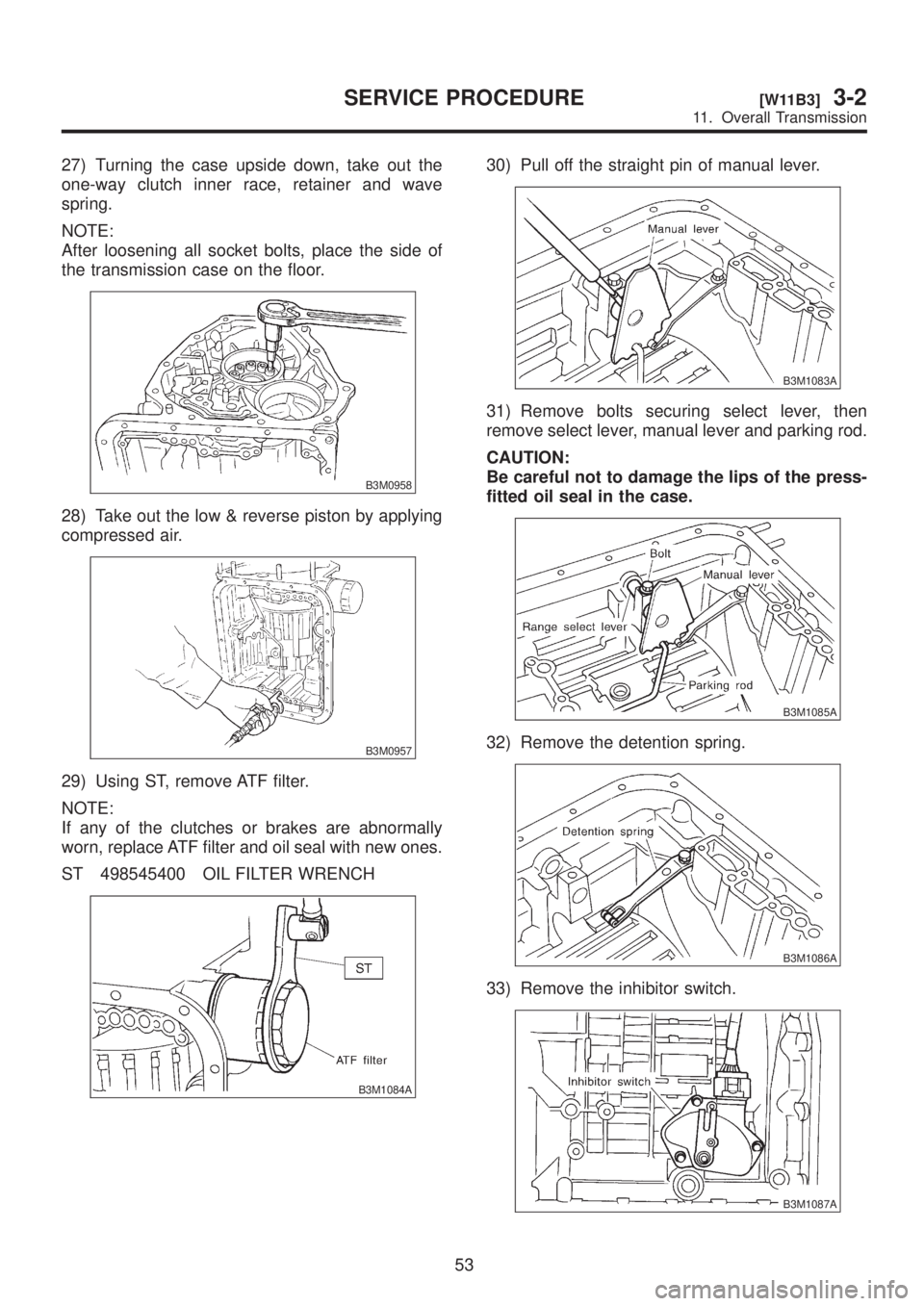
27) Turning the case upside down, take out the
one-way clutch inner race, retainer and wave
spring.
NOTE:
After loosening all socket bolts, place the side of
the transmission case on the floor.
B3M0958
28) Take out the low & reverse piston by applying
compressed air.
B3M0957
29) Using ST, remove ATF filter.
NOTE:
If any of the clutches or brakes are abnormally
worn, replace ATF filter and oil seal with new ones.
ST 498545400 OIL FILTER WRENCH
B3M1084A
30) Pull off the straight pin of manual lever.
B3M1083A
31) Remove bolts securing select lever, then
remove select lever, manual lever and parking rod.
CAUTION:
Be careful not to damage the lips of the press-
fitted oil seal in the case.
B3M1085A
32) Remove the detention spring.
B3M1086A
33) Remove the inhibitor switch.
B3M1087A
53
[W11B3]3-2SERVICE PROCEDURE
11. Overall Transmission
Page 738 of 1456
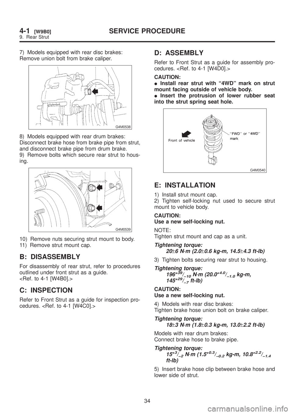
7) Models equipped with rear disc brakes:
Remove union bolt from brake caliper.
G4M0538
8) Models equipped with rear drum brakes:
Disconnect brake hose from brake pipe from strut,
and disconnect brake pipe from drum brake.
9) Remove bolts which secure rear strut to hous-
ing.
G4M0539
10) Remove nuts securing strut mount to body.
11) Remove strut mount cap.
B: DISASSEMBLY
For disassembly of rear strut, refer to procedures
outlined under front strut as a guide.
C: INSPECTION
Refer to Front Strut as a guide for inspection pro-
cedures.
D: ASSEMBLY
Refer to Front Strut as a guide for assembly pro-
cedures.
CAUTION:
IInstall rear strut with ª4WDº mark on strut
mount facing outside of vehicle body.
IInsert the protrusion of lower rubber seat
into the strut spring seat hole.
G4M0540
E: INSTALLATION
1) Install strut mount cap.
2) Tighten self-locking nut used to secure strut
mount to vehicle body.
CAUTION:
Use a new self-locking nut.
NOTE:
Tighten strut mount and cap as a unit.
Tightening torque:
20
±6 N´m (2.0±0.6 kg-m, 14.5±4.3 ft-lb)
3) Tighten bolts securing rear strut to housing.
Tightening torque:
196+39/þ10N´m (20.0+4.0/þ1.0kg-m,
145+29/þ7ft-lb)
CAUTION:
Use a new self-locking nut.
4) Models with rear disc brakes:
Tighten brake hose union bolt on brake caliper.
Tightening torque:
18
±3 N´m (1.8±0.3 kg-m, 13.0±2.2 ft-lb)
Models with rear drum brakes:
Connect brake hose to brake pipe.
Tightening torque:
15+3/þ2N´m (1.5+0.3/þ0.2kg-m, 10.8+2.2/þ1.4ft-lb)
5) Insert brake hose clip between brake hose and
lower side of strut.
34
4-1[W9B0]SERVICE PROCEDURE
9. Rear Strut
Page 766 of 1456

11) Using ST1 and ST2, press bearing into hub.
ST1 927080000 HUB STAND
ST2 927450000 HUB INSTALLER
G4M0262
E: INSTALLATION
1. DISC BRAKE
1) Connect rear housing assembly and strut
assembly.
CAUTION:
Use a new self-locking nut.
Tightening torque:
147
±15 N´m (15±1.5 kg-m, 108±11 ft-lb)
2) Fit BJ (bell joint) to rear housing splines.
CAUTION:
Be careful not to damage inner oil seal lip.
3) Connect rear housing assembly to lateral link
assembly.
CAUTION:
Use a new self-locking nut.
Tightening torque:
137
±20 N´m (14±2 kg-m, 101±14 ft-lb)
G4M0245
4) Connect rear housing assembly to trailing link
assembly.
CAUTION:
Use a new self-locking nut.
Tightening torque:
98 Ð 127 N´m (10 Ð 13 kg-m, 72 Ð 94
ft-lb)
G4M0246
5) Connect parking brake cable to parking brake.
6) Install disc rotor on rear housing assembly.
7) Install disc brake caliper on back plate.
Tightening torque:
52
±6 N´m (5.3±0.6 kg-m, 38.3±4.3 ft-lb)
G4M0240
8) Install rear speed sensor to back plate (only
vehicle equipped with ABS).
G4M0266
9) Bleed air from brake system.
10) Adjust parking brake lever stroke by turning
adjuster.
11) Move brake lever back to apply brakes. While
depressing brake pedal, tighten axle nut using a
20
4-2[W2E1]SERVICE PROCEDURE
2. Rear Axle