1999 SUBARU LEGACY brake fluid
[x] Cancel search: brake fluidPage 415 of 1456
1. General
A: PRECAUTION
When servicing clutch system, pay attention to the
following items.
1. MECHANICAL APPLICATION TYPE
1) Check the routing of clutch cable for smooth-
ness.
2) Excessive tightness or looseness of clutch
cable have a bad influence upon the cable durabil-
ity.
3) Apply grease sufficiently to the connecting por-
tion of clutch pedal.
4) Apply grease sufficiently to the release lever
portion.
5) Position clutch cable through the center of toe
board hole and route it smoothly. Adjustment is
done by moving the outer cable.
6) Make sure not to let the clutch chatter when
starting forward or rearward. If clutch chattering
occurs, readjust so that the bend of clutch outer
cable becomes flatter.
2. HYDRAULIC APPLICATION TYPE
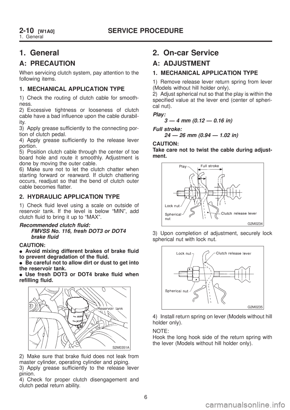
1) Check fluid level using a scale on outside of
reservoir tank. If the level is below ªMINº, add
clutch fluid to bring it up to ªMAXº.
Recommended clutch fluid:
FMVSS No. 116, fresh DOT3 or DOT4
brake fluid
CAUTION:
IAvoid mixing different brakes of brake fluid
to prevent degradation of the fluid.
IBe careful not to allow dirt or dust to get into
the reservoir tank.
IUse fresh DOT3 or DOT4 brake fluid when
refilling fluid.
S2M0351A
2) Make sure that brake fluid does not leak from
master cylinder, operating cylinder and piping.
3) Apply grease sufficiently to the release lever
pinion.
4) Check for proper clutch disengagement and
clutch pedal return ability.
2. On-car Service
A: ADJUSTMENT
1. MECHANICAL APPLICATION TYPE
1) Remove release lever return spring from lever
(Models without hill holder only).
2) Adjust spherical nut so that the play is within the
specified value at the lever end (center of spheri-
cal nut).
Play:
3Ð4mm(0.12 Ð 0.16 in)
Full stroke:
24 Ð 26 mm (0.94 Ð 1.02 in)
CAUTION:
Take care not to twist the cable during adjust-
ment.
G2M0234
3) Upon completion of adjustment, securely lock
spherical nut with lock nut.
G2M0235
4) Install return spring on lever (Models without hill
holder only).
NOTE:
Hook the long hook side of the return spring with
the lever (Models without hill holder only).
6
2-10[W1A0]SERVICE PROCEDURE
1. General
Page 416 of 1456
1. General
A: PRECAUTION
When servicing clutch system, pay attention to the
following items.
1. MECHANICAL APPLICATION TYPE
1) Check the routing of clutch cable for smooth-
ness.
2) Excessive tightness or looseness of clutch
cable have a bad influence upon the cable durabil-
ity.
3) Apply grease sufficiently to the connecting por-
tion of clutch pedal.
4) Apply grease sufficiently to the release lever
portion.
5) Position clutch cable through the center of toe
board hole and route it smoothly. Adjustment is
done by moving the outer cable.
6) Make sure not to let the clutch chatter when
starting forward or rearward. If clutch chattering
occurs, readjust so that the bend of clutch outer
cable becomes flatter.
2. HYDRAULIC APPLICATION TYPE
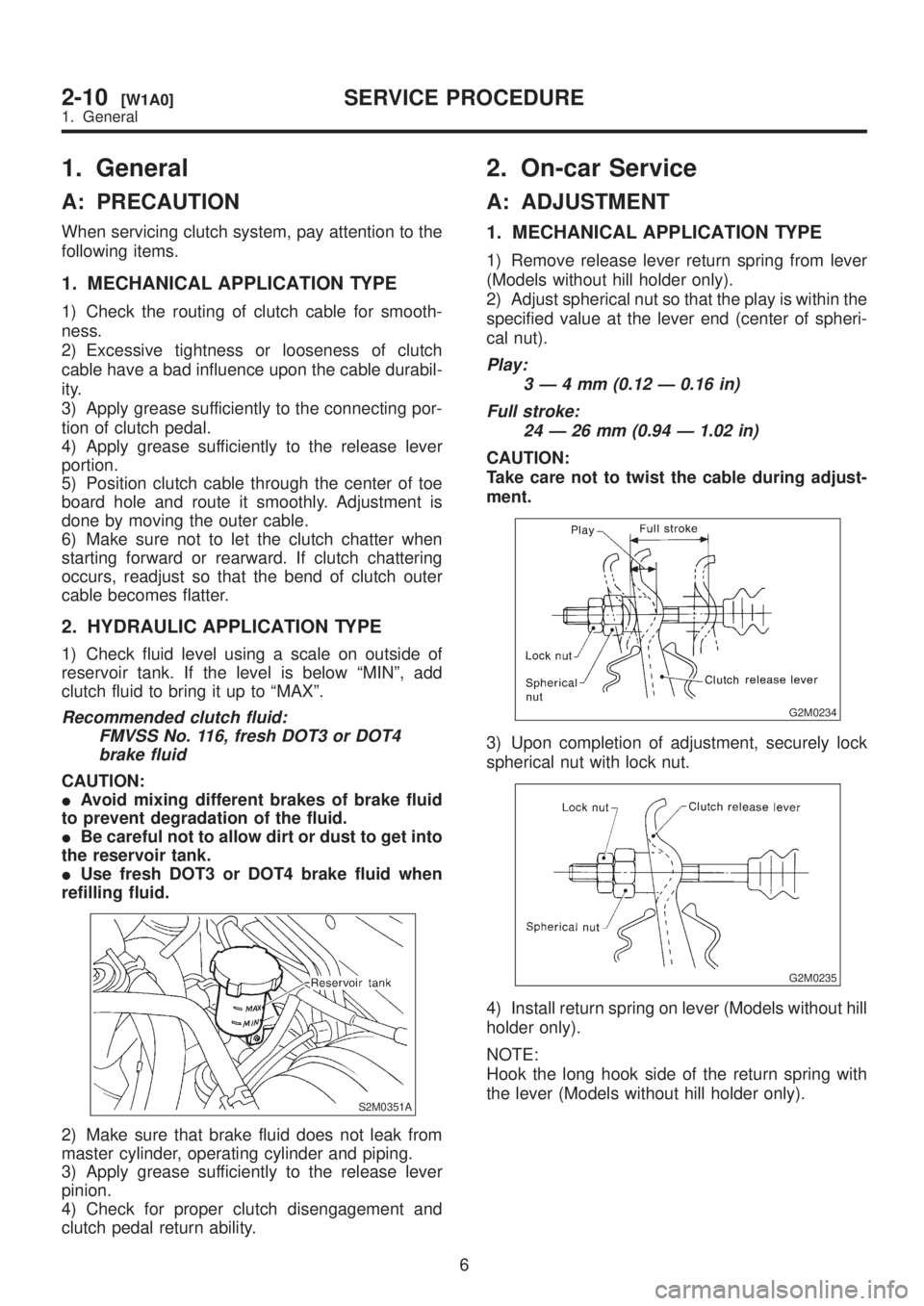
1) Check fluid level using a scale on outside of
reservoir tank. If the level is below ªMINº, add
clutch fluid to bring it up to ªMAXº.
Recommended clutch fluid:
FMVSS No. 116, fresh DOT3 or DOT4
brake fluid
CAUTION:
IAvoid mixing different brakes of brake fluid
to prevent degradation of the fluid.
IBe careful not to allow dirt or dust to get into
the reservoir tank.
IUse fresh DOT3 or DOT4 brake fluid when
refilling fluid.
S2M0351A
2) Make sure that brake fluid does not leak from
master cylinder, operating cylinder and piping.
3) Apply grease sufficiently to the release lever
pinion.
4) Check for proper clutch disengagement and
clutch pedal return ability.
2. On-car Service
A: ADJUSTMENT
1. MECHANICAL APPLICATION TYPE
1) Remove release lever return spring from lever
(Models without hill holder only).
2) Adjust spherical nut so that the play is within the
specified value at the lever end (center of spheri-
cal nut).
Play:
3Ð4mm(0.12 Ð 0.16 in)
Full stroke:
24 Ð 26 mm (0.94 Ð 1.02 in)
CAUTION:
Take care not to twist the cable during adjust-
ment.
G2M0234
3) Upon completion of adjustment, securely lock
spherical nut with lock nut.
G2M0235
4) Install return spring on lever (Models without hill
holder only).
NOTE:
Hook the long hook side of the return spring with
the lever (Models without hill holder only).
6
2-10[W1A0]SERVICE PROCEDURE
1. General
Page 417 of 1456
5) Depress clutch pedal to assure there is no
abnormality in the clutch system.
G2M0236
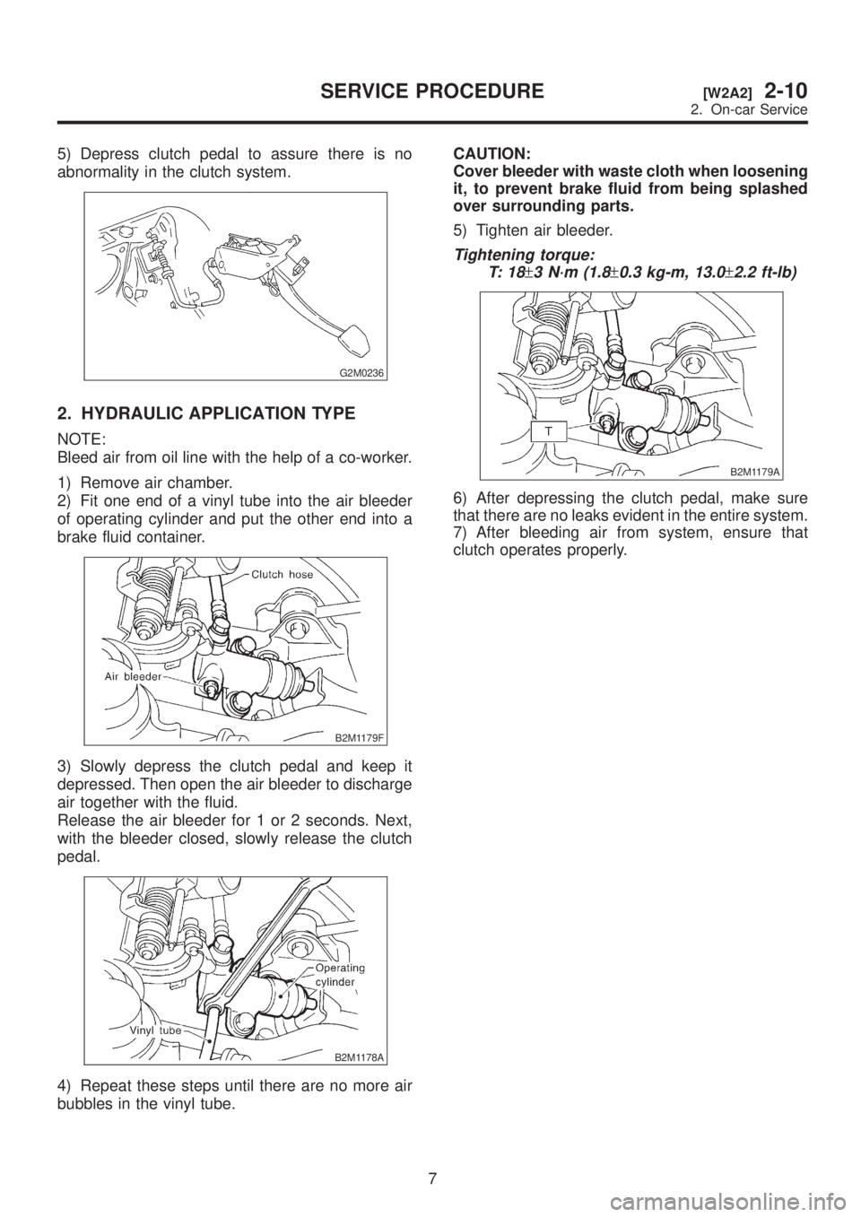
2. HYDRAULIC APPLICATION TYPE
NOTE:
Bleed air from oil line with the help of a co-worker.
1) Remove air chamber.
2) Fit one end of a vinyl tube into the air bleeder
of operating cylinder and put the other end into a
brake fluid container.
B2M1179F
3) Slowly depress the clutch pedal and keep it
depressed. Then open the air bleeder to discharge
air together with the fluid.
Release the air bleeder for 1 or 2 seconds. Next,
with the bleeder closed, slowly release the clutch
pedal.
B2M1178A
4) Repeat these steps until there are no more air
bubbles in the vinyl tube.CAUTION:
Cover bleeder with waste cloth when loosening
it, to prevent brake fluid from being splashed
over surrounding parts.
5) Tighten air bleeder.
Tightening torque:
T: 1 8
±3 N´m (1.8±0.3 kg-m, 13.0±2.2 ft-lb)
B2M1179A
6) After depressing the clutch pedal, make sure
that there are no leaks evident in the entire system.
7) After bleeding air from system, ensure that
clutch operates properly.
7
[W2A2]2-10SERVICE PROCEDURE
2. On-car Service
Page 426 of 1456
![SUBARU LEGACY 1999 Service Repair Manual 5. Operating Cylinder
A: REMOVAL AND INSTALLATION
1) Remove air chamber.
<Ref. to 2-7 [W18A0].>
B2M1265
2) Remove clutch hose from operating cylinder.
CAUTION:
Cover hose joint to prevent brake fluid SUBARU LEGACY 1999 Service Repair Manual 5. Operating Cylinder
A: REMOVAL AND INSTALLATION
1) Remove air chamber.
<Ref. to 2-7 [W18A0].>
B2M1265
2) Remove clutch hose from operating cylinder.
CAUTION:
Cover hose joint to prevent brake fluid](/manual-img/17/57435/w960_57435-425.png)
5. Operating Cylinder
A: REMOVAL AND INSTALLATION
1) Remove air chamber.
B2M1265
2) Remove clutch hose from operating cylinder.
CAUTION:
Cover hose joint to prevent brake fluid from
flowing out.
B2M1179B
3) Remove operating cylinder from transmission.
B2M1263
4) Installation is in the reverse order of removal.
NOTE:
Before installing operating cylinder, apply grease
(SUNLIGHT 2: P/N 003602010) to contact point of
release lever and operating cylinder.
Tightening torque:
T1: 18
±3 N´m (1.8±0.3 kg-m, 13.0±2.2 ft-lb)
T2: 37
±3 N´m (3.8±0.3 kg-m, 27.5±2.2 ft-lb)
B2M1179C
5) After bleeding air from operating cylinder,
ensure that clutch operates properly.
15
[W5A0]2-10SERVICE PROCEDURE
5. Operating Cylinder
Page 427 of 1456
6. Master Cylinder and
Reservoir Tank
A: REMOVAL
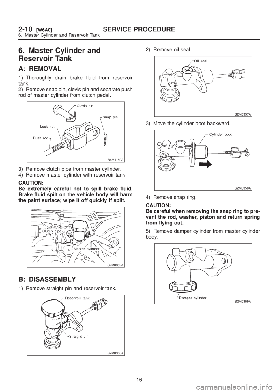
1) Thoroughly drain brake fluid from reservoir
tank.
2) Remove snap pin, clevis pin and separate push
rod of master cylinder from clutch pedal.
B4M1189A
3) Remove clutch pipe from master cylinder.
4) Remove master cylinder with reservoir tank.
CAUTION:
Be extremely careful not to spill brake fluid.
Brake fluid spilt on the vehicle body will harm
the paint surface; wipe it off quickly if spilt.
S2M0352A
B: DISASSEMBLY
1) Remove straight pin and reservoir tank.
S2M0356A
2) Remove oil seal.
S2M0357A
3) Move the cylinder boot backward.
S2M0358A
4) Remove snap ring.
CAUTION:
Be careful when removing the snap ring to pre-
vent the rod, washer, piston and return spring
from flying out.
5) Remove damper cylinder from master cylinder
body.
S2M0359A
16
2-10[W6A0]SERVICE PROCEDURE
6. Master Cylinder and Reservoir Tank
Page 429 of 1456
7. Brake Fluid
A: REPLACEMENT
CAUTION:
IThe FMVSS No. 116, fresh DOT3 or 4 brake
fluid must be used.
ICover bleeder with waste cloth, when loos-
ening it, to prevent brake fluid from being
splashed over surrounding parts.
IAvoid mixing different brands of brake fluid
to prevent degrading the quality of the fluid.
IBe careful not to allow dirt or dust to get into
the reservoir tank.
NOTE:
IDuring bleeding operation, keep the clutch
reserve tank filled with brake fluid to eliminate entry
of air.
IClutch pedal operating must be very slow.
IFor convenience and safety, it is advisable to
have two man working.IThe amount of brake fluid required is approxi-
mately 70 m(2.4 US fl oz, 2.5 Imp fl oz) for total
clutch system.
1) Either jack-up vehicle and place a safety stand
under it, or lift-up vehicle.
2) Remove both front and rear wheels.
3) Draw out the brake fluid from reserve tank with
syringe.
4) Refill reservoir tank with recommended brake
fluid.
Recommended brake fluid:
FMVSS No. 116, fresh DOT3 or 4 brake
fluid
5) Bleed air from oil line with the help of a co-
worker.
18
2-10[W7A0]SERVICE PROCEDURE
7. Brake Fluid
Page 536 of 1456

No. Part Name Part NumberInside diameter
mm (in)Outside diameter
mm (in)Dimension
mm (in)Application
(1)Thrust needle
bearing806528050
806528060
806528070
806528080
806528090
80652810028.5 (1.122) 48 (1.89)4.1 (0.161)
4.3 (0.169)
4.5 (0.177)
4.7 (0.185)
4.9 (0.193)
5.1 (0.201)Adjusting total
end play
(2)Thrust needle
bearing806530040 30 (1.18) 47 (1.85) 3.8 (0.150)Place of high
clutch
(3)Thrust needle
bearing806551020 51 (2.01) 71 (2.80) 3.3 (0.130)Place of front sun
gear
(4)Thrust needle
bearing806535120 35 (1.38) 53 (2.09) 4.8 (0.189)Place of rear sun
gear
(5)Thrust needle
bearing806534060 35 (1.38) 53 (2.09) 3.3 (0.130)Place of rear sun
gear
(6)Thrust needle
bearing806558030 58 (2.28) 78 (3.07) 2.8 (0.110)Place of rear
internal gear
(7)Thrust needle
bearing806541020 39.7 (1.563) 54 (2.13) 3.6 (0.142)Place of one-way
clutch
(8)Thrust needle
bearing806536020
806535030
806535040
806535050
806535060
806535070
80653509036 (1.42) 53 (2.09)3.8 (0.150)
4.0 (0.157)
4.2 (0.165)
4.4 (0.173)
4.6 (0.181)
4.8 (0.189)
5.0 (0.197)Adjusting end play
of transfer clutch
D: FLUID PASSAGES
1. TRANSMISSION CASE (FRONT SIDE)
B3M0987A
(1) Low clutch pressure (2) Oil cooler inlet pressure (3) Low & reverse brake pressure
11
[S1D1]3-2SPECIFICATIONS AND SERVICE DATA
1. Automatic Transmission and Differential
Page 545 of 1456

4. Control Valve and Harness Routing
B3M0928A
(1) Stay
(2) Transmission harness
(3) O-ring
(4) O-ring
(5) Torque converter turbine speed
sensor
(6) O-ring
(7) Vehicle speed sensor 2 (Front)
(8) O-ring
(9) Vehicle speed sensor 1 (Rear)
(10) Upper valve body
(11) Accumulator piston(12) Accumulator spring
(13) Side plate
(14) Separate plate
(15) Middle valve body
(16) Separate plate
(17) Fluid filter
(18) Fluid filter
(19) Lower valve body
(20) Shift solenoid 2
(21) Shift solenoid 1
(22) 2-4 brake timing solenoid
(23) Duty solenoid D (2-4 brake)(24) ATF temperature sensor
(25) Duty solenoid A (Line pressure)
(26) Low clutch timing solenoid
(27) Duty solenoid B (Lock-up)
(28) Oil strainer
Tightening torque: N´m (kg-m, ft-lb)
T1:
7±1 (0.7±0.1, 5.1±0.7)
T2:8±1 (0.8±0.1, 5.8±0.7)
20
3-2[C400]COMPONENT PARTS
4. Control Valve and Harness Routing