1999 SUBARU LEGACY spare wheel
[x] Cancel search: spare wheelPage 710 of 1456

B: INSPECTION AND ADJUSTMENT
1. WHEEL ARCH HEIGHT (FRONT AND
REAR)
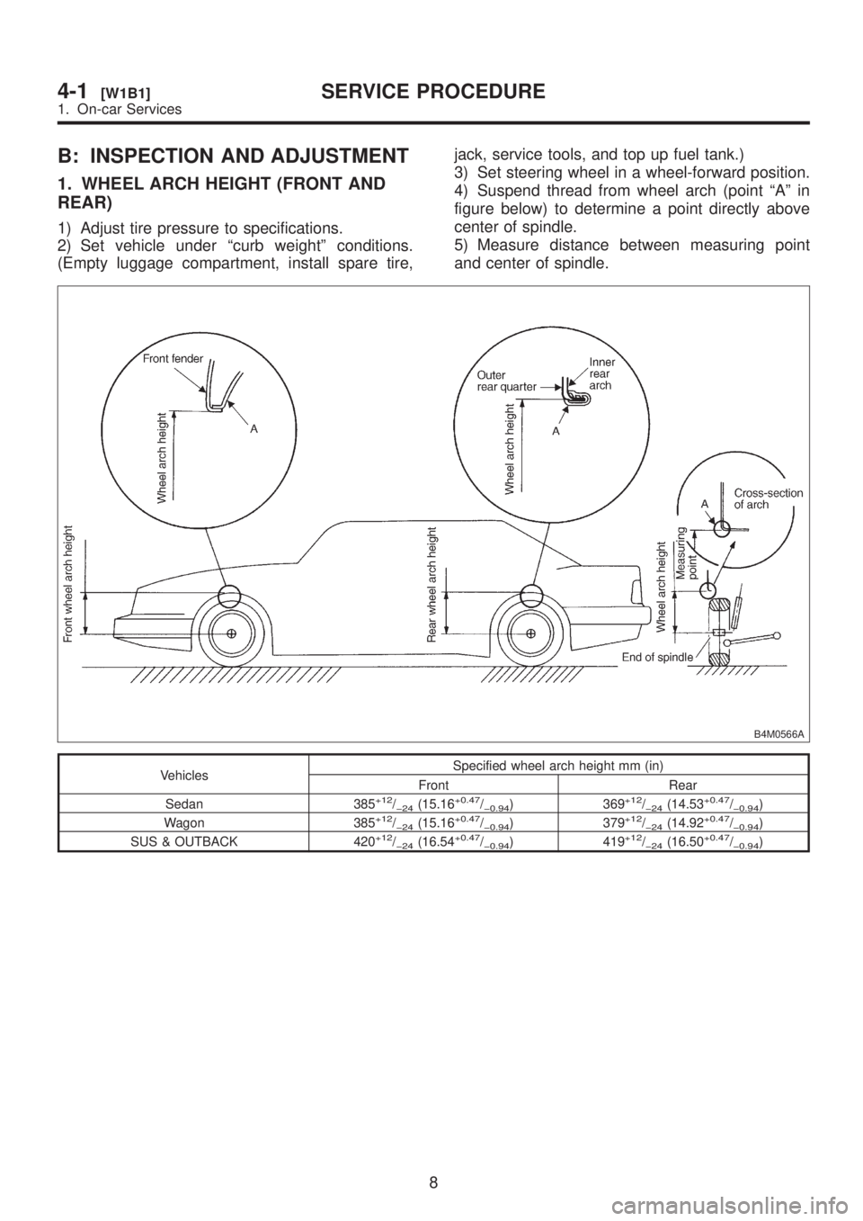
1) Adjust tire pressure to specifications.
2) Set vehicle under ªcurb weightº conditions.
(Empty luggage compartment, install spare tire,jack, service tools, and top up fuel tank.)
3) Set steering wheel in a wheel-forward position.
4) Suspend thread from wheel arch (point ªAº in
figure below) to determine a point directly above
center of spindle.
5) Measure distance between measuring point
and center of spindle.
B4M0566A
VehiclesSpecified wheel arch height mm (in)
Front Rear
Sedan 385
+12/þ24(15.16+0.47/þ0.94) 369+12/þ24(14.53+0.47/þ0.94)
Wagon 385+12/þ24(15.16+0.47/þ0.94) 379+12/þ24(14.92+0.47/þ0.94)
SUS & OUTBACK 420+12/þ24(16.54+0.47/þ0.94) 419+12/þ24(16.50+0.47/þ0.94)
8
4-1[W1B1]SERVICE PROCEDURE
1. On-car Services
Page 745 of 1456

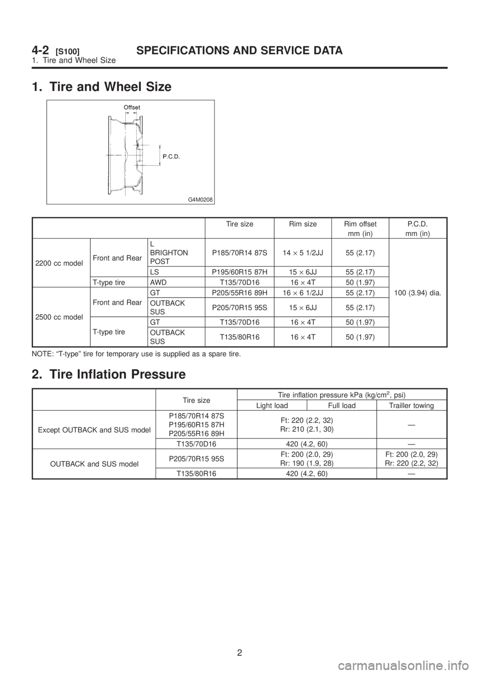
1. Tire and Wheel Size
G4M0208
Tire size Rim size Rim offset
mm (in)P.C.D.
mm (in)
2200 cc modelFront and RearL
BRIGHTON
POSTP185/70R14 87S 14´5 1/2JJ 55 (2.17)
100 (3.94) dia. LS P195/60R15 87H 15´6JJ 55 (2.17)
T-type tire AWD T135/70D16 16´4T 50 (1.97)
2500 cc modelFront and RearGT P205/55R16 89H 16´6 1/2JJ 55 (2.17)
OUTBACK
SUSP205/70R15 95S 15´6JJ 55 (2.17)
T-type tireGT T135/70D16 16´4T 50 (1.97)
OUTBACK
SUST135/80R16 16´4T 50 (1.97)
NOTE: ªT-typeº tire for temporary use is supplied as a spare tire.
2. Tire Inflation Pressure
Tire sizeTire inflation pressure kPa (kg/cm
2, psi)
Light load Full load Trailler towing
Except OUTBACK and SUS modelP185/70R14 87S
P195/60R15 87H
P205/55R16 89HFt: 220 (2.2, 32)
Rr: 210 (2.1, 30)Ð
T135/70D16 420 (4.2, 60) Ð
OUTBACK and SUS modelP205/70R15 95SFt: 200 (2.0, 29)
Rr: 190 (1.9, 28)Ft: 200 (2.0, 29)
Rr: 220 (2.2, 32)
T135/80R16 420 (4.2, 60) Ð
2
4-2[S100]SPECIFICATIONS AND SERVICE DATA
1. Tire and Wheel Size
Page 746 of 1456

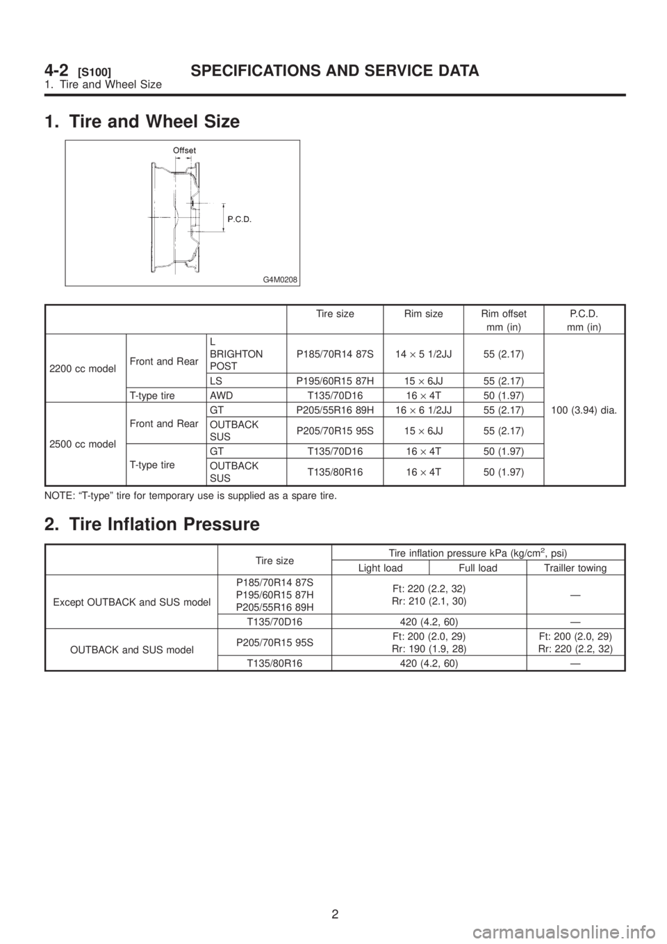
1. Tire and Wheel Size
G4M0208
Tire size Rim size Rim offset
mm (in)P.C.D.
mm (in)
2200 cc modelFront and RearL
BRIGHTON
POSTP185/70R14 87S 14´5 1/2JJ 55 (2.17)
100 (3.94) dia. LS P195/60R15 87H 15´6JJ 55 (2.17)
T-type tire AWD T135/70D16 16´4T 50 (1.97)
2500 cc modelFront and RearGT P205/55R16 89H 16´6 1/2JJ 55 (2.17)
OUTBACK
SUSP205/70R15 95S 15´6JJ 55 (2.17)
T-type tireGT T135/70D16 16´4T 50 (1.97)
OUTBACK
SUST135/80R16 16´4T 50 (1.97)
NOTE: ªT-typeº tire for temporary use is supplied as a spare tire.
2. Tire Inflation Pressure
Tire sizeTire inflation pressure kPa (kg/cm
2, psi)
Light load Full load Trailler towing
Except OUTBACK and SUS modelP185/70R14 87S
P195/60R15 87H
P205/55R16 89HFt: 220 (2.2, 32)
Rr: 210 (2.1, 30)Ð
T135/70D16 420 (4.2, 60) Ð
OUTBACK and SUS modelP205/70R15 95SFt: 200 (2.0, 29)
Rr: 190 (1.9, 28)Ft: 200 (2.0, 29)
Rr: 220 (2.2, 32)
T135/80R16 420 (4.2, 60) Ð
2
4-2[S100]SPECIFICATIONS AND SERVICE DATA
1. Tire and Wheel Size
Page 827 of 1456
![SUBARU LEGACY 1999 Service Repair Manual 5. Control Valve (Power Steering Gearbox) [LHD model]
A: CHECKING OIL LEAKING POINTS
B4M1132A
(1) Power cylinder
(2) Cylinder
(3) Rack piston
(4) Rack axle
(5) Input shaft(6) Torsion bar
(7) Valve hou SUBARU LEGACY 1999 Service Repair Manual 5. Control Valve (Power Steering Gearbox) [LHD model]
A: CHECKING OIL LEAKING POINTS
B4M1132A
(1) Power cylinder
(2) Cylinder
(3) Rack piston
(4) Rack axle
(5) Input shaft(6) Torsion bar
(7) Valve hou](/manual-img/17/57435/w960_57435-826.png)
5. Control Valve (Power Steering Gearbox) [LHD model]
A: CHECKING OIL LEAKING POINTS
B4M1132A
(1) Power cylinder
(2) Cylinder
(3) Rack piston
(4) Rack axle
(5) Input shaft(6) Torsion bar
(7) Valve housing
(8) Valve body
(9) Control valve
(10) Pipe B(11) Pipe A
(12) Pinion
(13) Pinion axle
1. OIL LEAKING POINTS
1) If leak point is other than a, b, c, or d, perform
check step 5) in ªOIL LEAK CHECK PROCEDURE
AND REPLACEMENT PARTSº before dismounting
gearbox from vehicle.
gearbox is dismounted without confirming where
the leak is, it must be mounted again to locate the
leak point.
2) Even if the location of the leak can be easily
found by observing the leaking condition, it is nec-
essary to thoroughly remove the oil from the sus-
pected portion and turn the steering wheel from
lock to lock about 30 to 40 times with engine
running, then make comparison of the suspected
portion between immediately after and several
hours after this operation.
3) Before starting oil leak repair work, be sure to
clean the gearbox, hoses, pipes, and surrounding
parts. After completing repair work, clean these
areas again.
2. OIL LEAK CHECK PROCEDURE AND
REPLACEMENT PARTS
NOTE:
Parts requiring replacement are described in the
smallest unit of spare parts including damaged
parts and spare parts damaged. In actual disas-sembly work, accidental damage as well as inevi-
table damage to some related parts must be taken
into account, and spare parts for them must also
be prepared. However, it is essential to pinpoint the
cause of trouble, and limit the number of replace-
ment parts as much as possible.
1) Leakage from ªaº
The oil seal is damaged. Replace valve assembly
with a new one.
2) Leakage from ªbº
The torsion bar O-ring is damaged. Replace valve
assembly with a new one.
3) Leakage from ªcº
The oil seal is damaged. Replace valve assembly
with a new one.
4) Leakage from ªdº
The pipe is damaged. Replace the faulty pipe or
O-ring.
5) If leak is other than a, b, c, or d, and if oil is
leaking from the gearbox, move the right and left
boots toward tie-rod end side, respectively, with the
gearbox mounted to the vehicle, and remove oil
from the surrounding portions. Then, turn the steer-
ing wheel from lock to lock 30 to 40 times with the
engine running, then make comparison of the
leaked portion immediately after and several hours
after this operation.
35
[W5A2]4-3SERVICE PROCEDURE
5. Control Valve (Power Steering Gearbox) [LHD model]
Page 834 of 1456
![SUBARU LEGACY 1999 Service Repair Manual 6. Control Valve (Power Steering Gearbox) [RHD model]
A: CHECKING OIL LEAKING POINTS
B4M0668A
1. OIL LEAKING POINTS
1) If leak point is other than a, b, c, or d, perform
check step 5) in ªOIL LEAK CH SUBARU LEGACY 1999 Service Repair Manual 6. Control Valve (Power Steering Gearbox) [RHD model]
A: CHECKING OIL LEAKING POINTS
B4M0668A
1. OIL LEAKING POINTS
1) If leak point is other than a, b, c, or d, perform
check step 5) in ªOIL LEAK CH](/manual-img/17/57435/w960_57435-833.png)
6. Control Valve (Power Steering Gearbox) [RHD model]
A: CHECKING OIL LEAKING POINTS
B4M0668A
1. OIL LEAKING POINTS
1) If leak point is other than a, b, c, or d, perform
check step 5) in ªOIL LEAK CHECK PROCEDURE
AND REPLACEMENT PARTSº before dismounting
gearbox from vehicle.
gearbox is dismounted without confirming where
the leak is, it must be mounted again to locate the
leak point.
2) Even if the location of the leak can be easily
found by observing the leaking condition, it is nec-
essary to thoroughly remove the oil from the sus-
pected portion and turn the steering wheel from
lock to lock about 30 to 40 times with engine
running, then make comparison of the suspected
portion between immediately after and several
hours after this operation.
3) Before starting oil leak repair work, be sure to
clean the gearbox, hoses, pipes, and surrounding
parts. After completing repair work, clean these
areas again.
2. OIL LEAK CHECK PROCEDURE AND
REPLACEMENT PARTS
NOTE:
Parts requiring replacement are described in the
smallest unit of spare parts including damaged
parts and spare parts damaged. In actual disas-
sembly work, accidental damage as well as inevi-
table damage to some related parts must be taken
into account, and spare parts for them must also
be prepared. However, it is essential to pinpoint the
cause of trouble, and limit the number of replace-
ment parts as much as possible.
1) Leakage from ªaº
The oil seal is damaged. Replace valve assembly
with a new one.
2) Leakage from ªbº
The torsion bar O-ring is damaged. Replace valve
assembly with a new one.
3) Leakage from ªcº
The oil seal is damaged. Replace valve assembly
with a new one.
4) Leakage from ªdº
The pipe is damaged. Replace the faulty pipe or
O-ring.
5) If leak is other than a, b, c, or d, and if oil is
leaking from the gearbox, move the right and left
42
4-3[W6A0]SERVICE PROCEDURE
6. Control Valve (Power Steering Gearbox) [RHD model]
Page 934 of 1456

9) Remove air bleeder screws from the RL and RR
caliper bodies.
10) Connect the air bleeder screws to the FL and
FR caliper bodies.
11) Connect two pressure gauges to the RL and
RR caliper bodies.
12) Bleed air from the pressure gauges and the FL
and FR caliper bodies.
13) Perform ABS sequence control.
14) When the hydraulic unit begins to work, at first
the RR side performs decompression, holding, and
compression, and then the RL side performs
decompression, holding, and compression.
15) Read values indicated on the pressure
gauges and check if they meet the standard value.
16) After checking, remove the pressure gauges
from caliper bodies.
17) Connect the air bleeder screws to RL and RR
caliper bodies.
18) Bleed air from brake line.
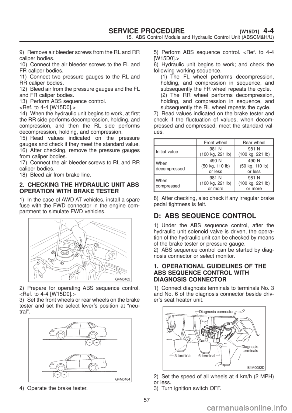
2. CHECKING THE HYDRAULIC UNIT ABS
OPERATION WITH BRAKE TESTER
1) In the case of AWD AT vehicles, install a spare
fuse with the FWD connector in the engine com-
partment to simulate FWD vehicles.
G4M0462
2) Prepare for operating ABS sequence control.
3) Set the front wheels or rear wheels on the brake
tester and set the select lever's position at ªneu-
tralº.
G4M0464
4) Operate the brake tester.5) Perform ABS sequence control.
6) Hydraulic unit begins to work; and check the
following working sequence.
(1) The FL wheel performs decompression,
holding, and compression in sequence, and
subsequently the FR wheel repeats the cycle.
(2) The RR wheel performs decompression,
holding, and compression in sequence, and
subsequently the RL wheel repeats the cycle.
7) Read values indicated on the brake tester and
check if the fluctuation of values, when decom-
pressed and compressed, meet the standard val-
ues.
Front wheel Rear wheel
Initial value981 N
(100 kg, 221 lb)981 N
(100 kg, 221 lb)
When
decompressed490 N
(50 kg, 110 lb)
or less490 N
(50 kg, 110 lb)
or less
When
compressed981 N
(100 kg, 221 lb)
or more981 N
(100 kg, 221 lb)
or more
8) After checking, also check if any irregular brake
pedal tightness is felt.
D: ABS SEQUENCE CONTROL
1) Under the ABS sequence control, after the
hydraulic unit solenoid valve is driven, the opera-
tion of the hydraulic unit can be checked by means
of the brake tester or pressure gauge.
2) ABS sequence control can be started by diag-
nosis connector or select monitor.
1. OPERATIONAL GUIDELINES OF THE
ABS SEQUENCE CONTROL WITH
DIAGNOSIS CONNECTOR
1) Connect diagnosis terminals to terminals No. 3
and No. 6 of the diagnosis connector beside driv-
er's seat heater unit.
B4M0082D
2) Set the speed of all wheels at 4 km/h (2 MPH)
or less.
3) Turn ignition switch OFF.
57
[W15D1]4-4SERVICE PROCEDURE
15. ABS Control Module and Hydraulic Control Unit (ABSCM&H/U)