1999 SUBARU LEGACY tires
[x] Cancel search: tiresPage 652 of 1456
2. Rear Differential
A: SPECIFICATIONS
Type of gearHypoid
MT AT
2200 cc 2500 cc 2200 cc 2500 cc
Gear ratio (Number of gear teeth) 3.900 (39/10) 4.111 (37/9) 4.111 (37/9) 4.444 (40/9)
Oil capacity 0.8(0.8 US qt, 0.7 Imp qt)
Rear differential gear oil GL-5
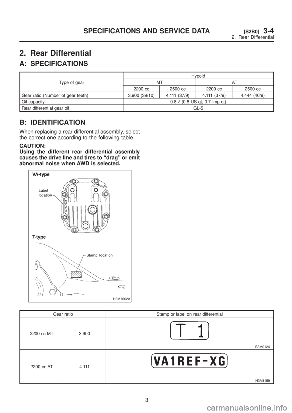
B: IDENTIFICATION
When replacing a rear differential assembly, select
the correct one according to the following table.
CAUTION:
Using the different rear differential assembly
causes the drive line and tires to ªdragº or emit
abnormal noise when AWD is selected.
H3M1662A
Gear ratio Stamp or label on rear differential
2200 cc MT 3.900
B3M0124
2200 cc AT 4.111
H3M1159
3
[S2B0]3-4SPECIFICATIONS AND SERVICE DATA
2. Rear Differential
Page 703 of 1456

2. Rear Differential
Symptom Possible cause Remedy
1. Oil leakage(1) Worn, scratched, or incorrectly seated front or
side oil seal. Scored, battered, or excessively worn
sliding surface of companion flange.Repair or replace.
(2) Clogged or damaged air breather. Clean, repair or replace.
(3) Loose bolts on differential spindle or side
retainer, or incorrectly fitted O-ring.Tighten bolts to specified torque.
Replace O-ring.
(4) Loose rear cover attaching bolts or damaged
gasket.Tighten bolts to specified torque.
Replace gasket and apply liquid
packing.
(5) Loose oil filler or drain plug. Retighten and apply liquid packing.
(6) Wear, damage or incorrectly fitting for spindle,
side retainer and oil seal.Repair or replace.
2. Seizure
NOTE:
Seized or damaged parts should
be replaced, and also other parts
should be thoroughly checked for
any defect and should be repaired
or replaced as required.(1) Insufficient backlash for hypoid gear. Readjust or replace.
(2) Excessive preload for side, rear, or front bearing. Readjust or replace.
(3) Insufficient or improper oil used. Replace seized part and fill with
specified oil to specified level.
3. Damage
NOTE:
Damaged parts should be
replaced, and also other parts
should be thoroughly checked for
any defect and should be repaired
or replaced as required.(1) Improper backlash for hypoid gear. Replace.
(2) Insufficient or excessive preload for side, rear, or
front bearing.Readjust or replace.
(3) Excessive backlash for differential gear. Replace gear or thrust washer.
(4) Loose bolts and nuts such as crown gear bolt. Retighten.
(5) Damage due to overloading. Replace.
4. Noises when starting or shift-
ing gears
NOTE:
Noises may be caused by differen-
tial assembly, universal joint, wheel
bearing, etc. Find out what is actu-
ally making noise before disassem-
bly.(1) Excessive backlash for hypoid gear. Readjust.
(2) Excessive backlash for differential gear. Replace gear or thrust washer.
(3) Insufficient preload for front or rear bearing. Readjust.
(4) Loose drive pinion nut. Tighten to specified torque.
(5) Loose bolts and nuts such as side bearing
retainer attaching bolt.Tighten to specified torque.
5. Noises when cornering(1) Damaged differential gear. Replace.
(2) Excessive wear or damage of thrust washer. Replace.
(3) Broken pinion mate shaft. Replace.
(4) Seized or damaged side bearing. Replace.
6. Gear noises
NOTE:
Since noises from engine, muffler,
transmission, propeller shaft, wheel
bearings, tires, and body are
sometimes mistaken for noises
from differential assembly, be care-
ful in checking them. Inspection
methods to locate noises include
coasting, accelerating, cruising,
and jacking-up all four wheels.
Perform these inspections accord-
ing to condition of trouble. When
listening to noises, shift gears into
four wheel drive and fourth speed
position, trying to pick up only dif-
ferential noise.(1) Improper tooth contact of hypoid gear. Readjust or replace hypoid gear
set.
(2) Improper backlash for hypoid gear. Readjust.
(3) Scored or chipped teeth of hypoid gear. Replace hypoid gear set.
(4) Seized hypoid gear. Replace hypoid gear set.
(5) Improper preload for front or rear bearings. Readjust.
(6) Seized, scored, or chipped front or rear bearing. Replace.
(7) Seized, scored, or chipped side bearing. Replace.
(8) Vibrating differential carrier. Replace.
52
3-4[K200]DIAGNOSTICS
2. Rear Differential
Page 712 of 1456
3. CASTER (FRONT)
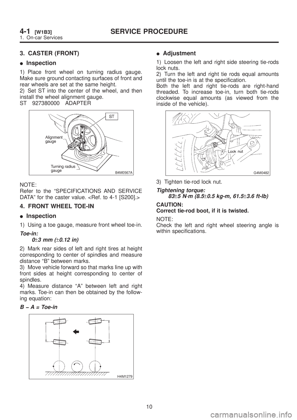
IInspection
1) Place front wheel on turning radius gauge.
Make sure ground contacting surfaces of front and
rear wheels are set at the same height.
2) Set ST into the center of the wheel, and then
install the wheel alignment gauge.
ST 927380000 ADAPTER
B4M0567A
NOTE:
Refer to the ªSPECIFICATIONS AND SERVICE
DATAº for the caster value.
4. FRONT WHEEL TOE-IN
IInspection
1) Using a toe gauge, measure front wheel toe-in.
Toe-in:
0
±3mm(±0.12 in)
2) Mark rear sides of left and right tires at height
corresponding to center of spindles and measure
distance ªBº between marks.
3) Move vehicle forward so that marks line up with
front sides at height corresponding to center of
spindles.
4) Measure distance ªAº between left and right
marks. Toe-in can then be obtained by the follow-
ing equation:
B þ A = Toe-in
H4M1279
IAdjustment
1) Loosen the left and right side steering tie-rods
lock nuts.
2) Turn the left and right tie rods equal amounts
until the toe-in is at the specification.
Both the left and right tie-rods are right-hand
threaded. To increase toe-in, turn both tie-rods
clockwise equal amounts (as viewed from the
inside of the vehicle).
G4M0482
3) Tighten tie-rod lock nut.
Tightening torque:
83
±5 N´m (8.5±0.5 kg-m, 61.5±3.6 ft-lb)
CAUTION:
Correct tie-rod boot, if it is twisted.
NOTE:
Check the left and right wheel steering angle is
within specifications.
10
4-1[W1B3]SERVICE PROCEDURE
1. On-car Services
Page 713 of 1456
5. REAR WHEEL TOE-IN
IInspection
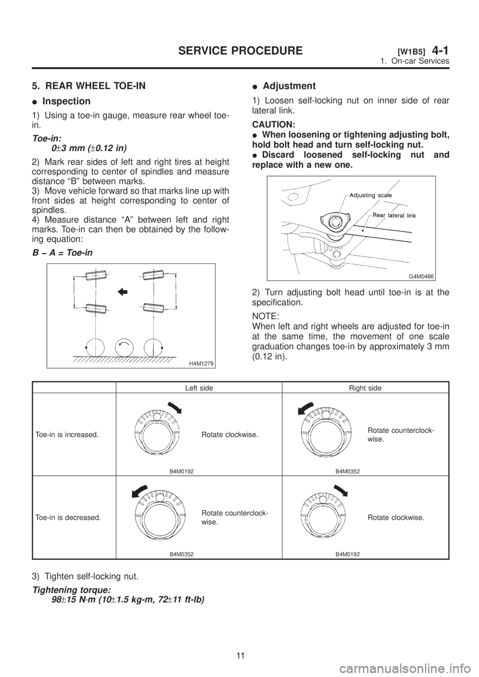
1) Using a toe-in gauge, measure rear wheel toe-
in.
Toe-in:
0
±3mm(±0.12 in)
2) Mark rear sides of left and right tires at height
corresponding to center of spindles and measure
distance ªBº between marks.
3) Move vehicle forward so that marks line up with
front sides at height corresponding to center of
spindles.
4) Measure distance ªAº between left and right
marks. Toe-in can then be obtained by the follow-
ing equation:
B þ A = Toe-in
H4M1279
IAdjustment
1) Loosen self-locking nut on inner side of rear
lateral link.
CAUTION:
IWhen loosening or tightening adjusting bolt,
hold bolt head and turn self-locking nut.
IDiscard loosened self-locking nut and
replace with a new one.
G4M0486
2) Turn adjusting bolt head until toe-in is at the
specification.
NOTE:
When left and right wheels are adjusted for toe-in
at the same time, the movement of one scale
graduation changes toe-in by approximately 3 mm
(0.12 in).
Left side Right side
Toe-in is increased.
B4M0192
Rotate clockwise.
B4M0352
Rotate counterclock-
wise.
Toe-in is decreased.
B4M0352
Rotate counterclock-
wise.
B4M0192
Rotate clockwise.
3) Tighten self-locking nut.
Tightening torque:
98
±15 N´m (10±1.5 kg-m, 72±11 ft-lb)
11
[W1B5]4-1SERVICE PROCEDURE
1. On-car Services
Page 726 of 1456
B: INSPECTION
1) Check bushing for cracks, fatigue or damage.
2) Check stabilizer link for deformities, cracks, or
damage, and bushing for protrusions from the hole
of stabilizer link and its play.
C: INSTALLATION
1) To install, reverse the removal procedure.
NOTE:
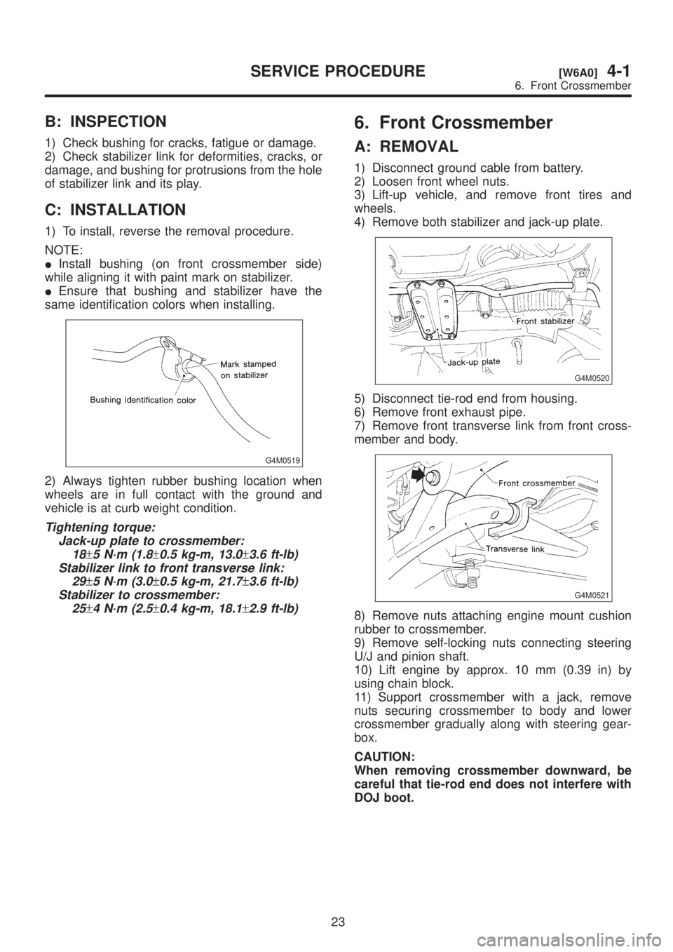
IInstall bushing (on front crossmember side)
while aligning it with paint mark on stabilizer.
IEnsure that bushing and stabilizer have the
same identification colors when installing.
G4M0519
2) Always tighten rubber bushing location when
wheels are in full contact with the ground and
vehicle is at curb weight condition.
Tightening torque:
Jack-up plate to crossmember:
18
±5 N´m (1.8±0.5 kg-m, 13.0±3.6 ft-lb)
Stabilizer link to front transverse link:
29
±5 N´m (3.0±0.5 kg-m, 21.7±3.6 ft-lb)
Stabilizer to crossmember:
25
±4 N´m (2.5±0.4 kg-m, 18.1±2.9 ft-lb)
6. Front Crossmember
A: REMOVAL
1) Disconnect ground cable from battery.
2) Loosen front wheel nuts.
3) Lift-up vehicle, and remove front tires and
wheels.
4) Remove both stabilizer and jack-up plate.
G4M0520
5) Disconnect tie-rod end from housing.
6) Remove front exhaust pipe.
7) Remove front transverse link from front cross-
member and body.
G4M0521
8) Remove nuts attaching engine mount cushion
rubber to crossmember.
9) Remove self-locking nuts connecting steering
U/J and pinion shaft.
10) Lift engine by approx. 10 mm (0.39 in) by
using chain block.
11) Support crossmember with a jack, remove
nuts securing crossmember to body and lower
crossmember gradually along with steering gear-
box.
CAUTION:
When removing crossmember downward, be
careful that tie-rod end does not interfere with
DOJ boot.
23
[W6A0]4-1SERVICE PROCEDURE
6. Front Crossmember
Page 727 of 1456
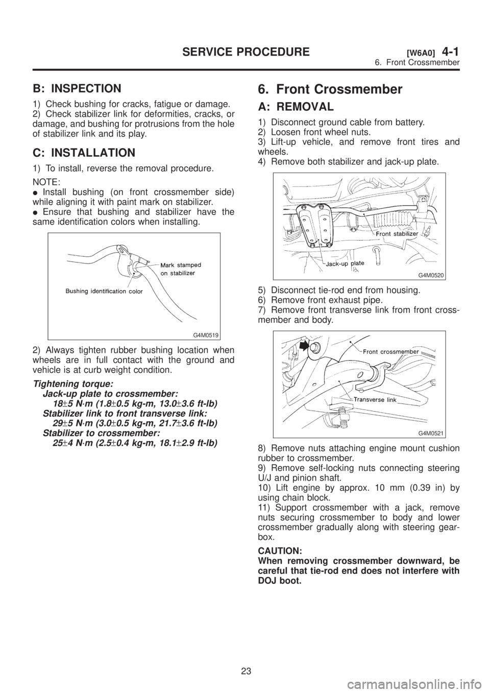
B: INSPECTION
1) Check bushing for cracks, fatigue or damage.
2) Check stabilizer link for deformities, cracks, or
damage, and bushing for protrusions from the hole
of stabilizer link and its play.
C: INSTALLATION
1) To install, reverse the removal procedure.
NOTE:
IInstall bushing (on front crossmember side)
while aligning it with paint mark on stabilizer.
IEnsure that bushing and stabilizer have the
same identification colors when installing.
G4M0519
2) Always tighten rubber bushing location when
wheels are in full contact with the ground and
vehicle is at curb weight condition.
Tightening torque:
Jack-up plate to crossmember:
18
±5 N´m (1.8±0.5 kg-m, 13.0±3.6 ft-lb)
Stabilizer link to front transverse link:
29
±5 N´m (3.0±0.5 kg-m, 21.7±3.6 ft-lb)
Stabilizer to crossmember:
25
±4 N´m (2.5±0.4 kg-m, 18.1±2.9 ft-lb)
6. Front Crossmember
A: REMOVAL
1) Disconnect ground cable from battery.
2) Loosen front wheel nuts.
3) Lift-up vehicle, and remove front tires and
wheels.
4) Remove both stabilizer and jack-up plate.
G4M0520
5) Disconnect tie-rod end from housing.
6) Remove front exhaust pipe.
7) Remove front transverse link from front cross-
member and body.
G4M0521
8) Remove nuts attaching engine mount cushion
rubber to crossmember.
9) Remove self-locking nuts connecting steering
U/J and pinion shaft.
10) Lift engine by approx. 10 mm (0.39 in) by
using chain block.
11) Support crossmember with a jack, remove
nuts securing crossmember to body and lower
crossmember gradually along with steering gear-
box.
CAUTION:
When removing crossmember downward, be
careful that tie-rod end does not interfere with
DOJ boot.
23
[W6A0]4-1SERVICE PROCEDURE
6. Front Crossmember
Page 787 of 1456

7. Steel Wheel and Tire
A: INSPECTION
1) Deformation or damage on the rim can cause
air leakage. Check the rim flange for deformation,
crack, or damage, and repair or replace as neces-
sary.
2) Take stone, glass, nail etc. off the tread groove.
3) Replace tire:
CAUTION:
IWhen replacing a tire, make sure to use only
the same size, construction and load range as
originally installed.
IAvoid mixing radial, belted bias or bias tires
on the vehicle.
(1) when large crack on side wall, damage or
crack on tread is found.
(2) when the ªtread wear indicatorº appears as
a solid band across the tread.
G4M0297
1. INSPECTION OF WHEEL RUNOUT
1) Jack-up vehicle until wheels clear the floor.
2) Slowly rotate wheel to check rim ªrunoutº using
a dial gauge.
G4M0298
Axial runout limit Radial runout limit
Steel wheel 1.5 mm (0.059 in)
Aluminum wheel 1.0 mm (0.039 in)
G4M0299
3) If rim runout exceeds specifications, remove
tire from rim and check runout while attaching dial
gauge to positions shown in figure.
4) If measured runout still exceeds specifications,
replace the wheel.
39
[W7A1]4-2SERVICE PROCEDURE
7. Steel Wheel and Tire
Page 790 of 1456

10. Installation of Wheel
Assembly to Vehicle
1) Attach the wheel to the hub by aligning the
wheel bolt hole with the hub bolt.
2) Temporarily attach the wheel nuts to the hub
bolts. (In the case of aluminum wheel, use
SUBARU genuine wheel nut for aluminum wheel.)
3) Manually tighten the nuts making sure the
wheel hub hole is aligned correctly to the guide
portion of hub.
4) Tighten the wheel nuts in a diagonal selection
to the specified torque. Use a wheel nut wrench.
Wheel nut tightening torque:
88
±10 N´m (9±1 kg-m, 65±7 ft-lb)
CAUTION:
ITighten the wheel nuts in two or three steps
by gradually increasing the torque and working
diagonally, until the specified torque is
reached. For drum brake models, excess tight-
ening of wheel nuts may cause wheels to ªjud-
derº.
IDo not depress the wrench with a foot;
Always use both hands when tightening.
IMake sure the bolt, nut and the nut seating
surface of the wheel are free from oils.
5) If a wheel is removed for replacement or for
repair of a puncture, retighten the wheel nuts to the
specified torque after running 1,000 km (600
miles).
11. Tire Rotation
If tires are maintained at the same positions for a
long period of time, uneven wear results.
Therefore, they should be periodically rotated.
This lengthens service life of tires.
CAUTION:
When rotating tires, replace unevenly worn or
damaged tires with new ones.
G4M0301
41
[W1100]4-2SERVICE PROCEDURE
11. Tire Rotation