1999 SUBARU LEGACY air bleeding
[x] Cancel search: air bleedingPage 417 of 1456
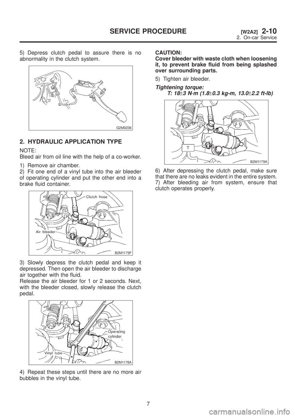
5) Depress clutch pedal to assure there is no
abnormality in the clutch system.
G2M0236
2. HYDRAULIC APPLICATION TYPE
NOTE:
Bleed air from oil line with the help of a co-worker.
1) Remove air chamber.
2) Fit one end of a vinyl tube into the air bleeder
of operating cylinder and put the other end into a
brake fluid container.
B2M1179F
3) Slowly depress the clutch pedal and keep it
depressed. Then open the air bleeder to discharge
air together with the fluid.
Release the air bleeder for 1 or 2 seconds. Next,
with the bleeder closed, slowly release the clutch
pedal.
B2M1178A
4) Repeat these steps until there are no more air
bubbles in the vinyl tube.CAUTION:
Cover bleeder with waste cloth when loosening
it, to prevent brake fluid from being splashed
over surrounding parts.
5) Tighten air bleeder.
Tightening torque:
T: 1 8
±3 N´m (1.8±0.3 kg-m, 13.0±2.2 ft-lb)
B2M1179A
6) After depressing the clutch pedal, make sure
that there are no leaks evident in the entire system.
7) After bleeding air from system, ensure that
clutch operates properly.
7
[W2A2]2-10SERVICE PROCEDURE
2. On-car Service
Page 426 of 1456
![SUBARU LEGACY 1999 Service Repair Manual 5. Operating Cylinder
A: REMOVAL AND INSTALLATION
1) Remove air chamber.
<Ref. to 2-7 [W18A0].>
B2M1265
2) Remove clutch hose from operating cylinder.
CAUTION:
Cover hose joint to prevent brake fluid](/manual-img/17/57435/w960_57435-425.png "SUBARU LEGACY 1999 Service Repair Manual 5. Operating Cylinder
A: REMOVAL AND INSTALLATION
1) Remove air chamber.
<Ref. to 2-7 [W18A0].>
B2M1265
2) Remove clutch hose from operating cylinder.
CAUTION:
Cover hose joint to prevent brake fluid")
5. Operating Cylinder
A: REMOVAL AND INSTALLATION
1) Remove air chamber.
B2M1265
2) Remove clutch hose from operating cylinder.
CAUTION:
Cover hose joint to prevent brake fluid from
flowing out.
B2M1179B
3) Remove operating cylinder from transmission.
B2M1263
4) Installation is in the reverse order of removal.
NOTE:
Before installing operating cylinder, apply grease
(SUNLIGHT 2: P/N 003602010) to contact point of
release lever and operating cylinder.
Tightening torque:
T1: 18
±3 N´m (1.8±0.3 kg-m, 13.0±2.2 ft-lb)
T2: 37
±3 N´m (3.8±0.3 kg-m, 27.5±2.2 ft-lb)
B2M1179C
5) After bleeding air from operating cylinder,
ensure that clutch operates properly.
15
[W5A0]2-10SERVICE PROCEDURE
5. Operating Cylinder
Page 428 of 1456

C: INSPECTION
If any damage, deformation, wear, swelling, rust or
other faults are found on the cylinder, piston, push
rod, fluid reservoir, return spring and gasket,
replace the faulty part.
S2M0353A
(A) Master cylinder body
(B) Return spring
(C) Piston
(D) Snap ring
(E) Rod assy
(F) Washer
(G) Damper cylinder
D: ASSEMBLY
CAUTION:
Apply a coat of grease to the contacting sur-
faces of the push rod and piston before instal-
lation.
1) To assemble the master cylinder reverse the
sequence of disassembly procedure.
2) Install damper cylinder washer. Install damper
cylinder and tighten to the specified torque.
Tightening torque:
T: 46.6
±7.4 N´m (4.75±0.75 kg-m, 34.4±5.4
ft-lb)
E: INSTALLATION
1) Install master cylinder to body, and install clutch
pipe to master cylinder.
CAUTION:
Check that pipe is routed properly.
Tightening torque:
T: 1 8
±3 N´m (1.8±0.3 kg-m, 13.0±2.2 ft-lb)
S2M0352B
2) Connect push rod of master cylinder to clutch
pedal, and install clevis pin and snap pin.
NOTE:
Apply grease to clevis pin.
B4M1189C
(A) Clevis pin
(B) Snap pin
(C) Push rod
3) After bleeding air from system, ensure that
clutch operates properly.
17
[W6E0]2-10SERVICE PROCEDURE
6. Master Cylinder and Reservoir Tank
Page 429 of 1456
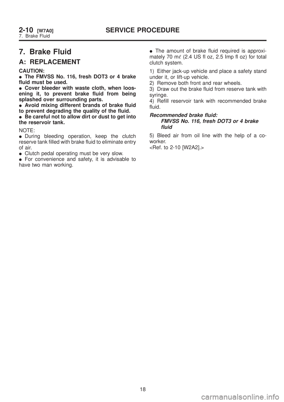
7. Brake Fluid
A: REPLACEMENT
CAUTION:
IThe FMVSS No. 116, fresh DOT3 or 4 brake
fluid must be used.
ICover bleeder with waste cloth, when loos-
ening it, to prevent brake fluid from being
splashed over surrounding parts.
IAvoid mixing different brands of brake fluid
to prevent degrading the quality of the fluid.
IBe careful not to allow dirt or dust to get into
the reservoir tank.
NOTE:
IDuring bleeding operation, keep the clutch
reserve tank filled with brake fluid to eliminate entry
of air.
IClutch pedal operating must be very slow.
IFor convenience and safety, it is advisable to
have two man working.IThe amount of brake fluid required is approxi-
mately 70 m(2.4 US fl oz, 2.5 Imp fl oz) for total
clutch system.
1) Either jack-up vehicle and place a safety stand
under it, or lift-up vehicle.
2) Remove both front and rear wheels.
3) Draw out the brake fluid from reserve tank with
syringe.
4) Refill reservoir tank with recommended brake
fluid.
Recommended brake fluid:
FMVSS No. 116, fresh DOT3 or 4 brake
fluid
5) Bleed air from oil line with the help of a co-
worker.
18
2-10[W7A0]SERVICE PROCEDURE
7. Brake Fluid
Page 860 of 1456
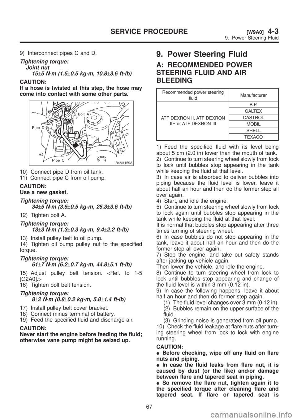
9) Interconnect pipes C and D.
Tightening torque:
Joint nut
15
±5 N´m (1.5±0.5 kg-m, 10.8±3.6 ft-lb)
CAUTION:
If a hose is twisted at this step, the hose may
come into contact with some other parts.
B4M1159A
10) Connect pipe D from oil tank.
11) Connect pipe C from oil pump.
CAUTION:
Use a new gasket.
Tightening torque:
34
±5 N´m (3.5±0.5 kg-m, 25.3±3.6 ft-lb)
12) Tighten bolt A.
Tightening torque:
13
±3 N´m (1.3±0.3 kg-m, 9.4±2.2 ft-lb)
13) Install pulley belt to oil pump.
14) Tighten oil pump pulley nut to the specified
torque.
Tightening torque:
61
±7 N´m (6.2±0.7 kg-m, 44.8±5.1 ft-lb)
15) Adjust pulley belt tension.
16) Tighten bolt belt tension.
Tightening torque:
8
±2 N´m (0.8±0.2 kg-m, 5.8±1.4 ft-lb)
17) Install pulley belt cover bracket.
18) Connect minus terminal of battery.
19) Feed the specified fluid and discharge air.
CAUTION:
Never start the engine before feeding the fluid;
otherwise vane pump might be seized up.
9. Power Steering Fluid
A: RECOMMENDED POWER
STEERING FLUID AND AIR
BLEEDING
Recommended power steering
fluidManufacturer
ATF DEXRON II, ATF DEXRON
IIE or ATF DEXRON IIIB.P.
CALTEX
CASTROL
MOBIL
SHELL
TEXACO
1) Feed the specified fluid with its level being
about 5 cm (2.0 in) lower than the mouth of tank.
2) Continue to turn steering wheel slowly from lock
to lock until bubbles stop appearing in the tank
while keeping the fluid at that level.
3) In case air is absorbed to deliver bubbles into
piping because the fluid level is lower, leave it
about half an hour and then do the former step all
over again.
4) Start, and idle the engine.
5) Continue to turn steering wheel slowly from lock
to lock again until bubbles stop appearing in the
tank while keeping the fluid at that level.
It is normal that bubbles stop appearing after three
times turning of steering wheel.
6) In case bubbles do not stop appearing in the
tank, leave it about half an hour and then do the
former step all over again.
7) Stop the engine, and take out safety stands
after jacking up vehicle again.
Then lower the vehicle, and idle the engine.
8) Continue to turn steering wheel from lock to
lock until bubbles stop appearing and change of
the fluid level is within 3 mm (0.12 in).
9) In case the following happens, leave it about
half an hour and then do former step again.
(1) The fluid level changes over 3 mm (0.12 in).
(2) Bubbles remain on the upper surface of the
fluid.
(3) Grinding noise is generated from oil pump.
10) Check the fluid leakage at flare nuts after turn-
ing steering wheel from lock to lock with engine
running.
CAUTION:
IBefore checking, wipe off any fluid on flare
nuts and piping.
IIn case the fluid leaks from flare nut, it is
caused by dust (or the like) and/or damage
between flare and tapered seat in piping.
ISo remove the flare nut, tighten again it to
the specified torque after cleaning flare and
tapered seat. If flare or tapered seat is
67
[W9A0]4-3SERVICE PROCEDURE
9. Power Steering Fluid
Page 861 of 1456
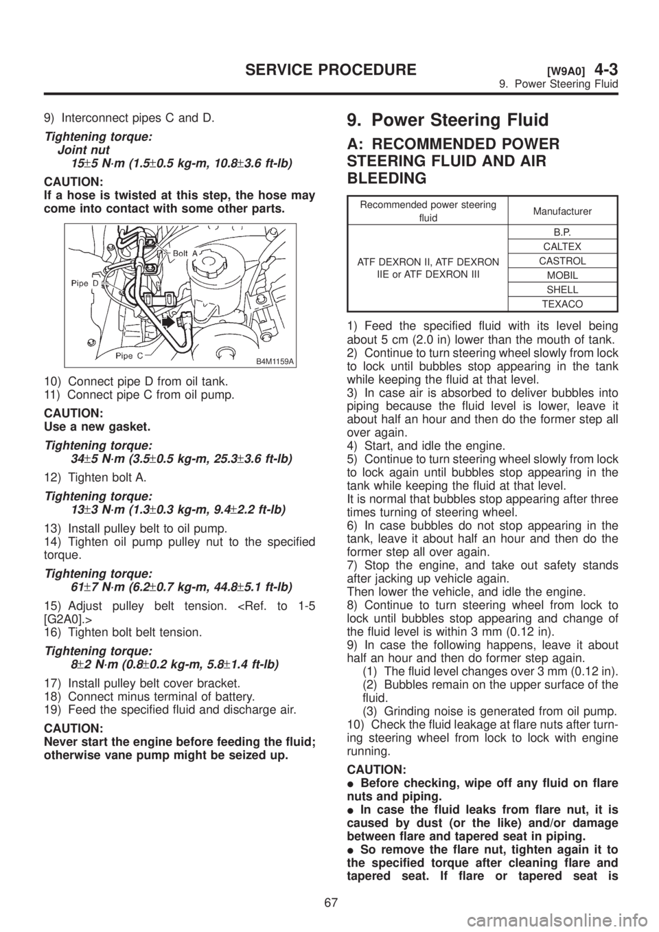
9) Interconnect pipes C and D.
Tightening torque:
Joint nut
15
±5 N´m (1.5±0.5 kg-m, 10.8±3.6 ft-lb)
CAUTION:
If a hose is twisted at this step, the hose may
come into contact with some other parts.
B4M1159A
10) Connect pipe D from oil tank.
11) Connect pipe C from oil pump.
CAUTION:
Use a new gasket.
Tightening torque:
34
±5 N´m (3.5±0.5 kg-m, 25.3±3.6 ft-lb)
12) Tighten bolt A.
Tightening torque:
13
±3 N´m (1.3±0.3 kg-m, 9.4±2.2 ft-lb)
13) Install pulley belt to oil pump.
14) Tighten oil pump pulley nut to the specified
torque.
Tightening torque:
61
±7 N´m (6.2±0.7 kg-m, 44.8±5.1 ft-lb)
15) Adjust pulley belt tension.
16) Tighten bolt belt tension.
Tightening torque:
8
±2 N´m (0.8±0.2 kg-m, 5.8±1.4 ft-lb)
17) Install pulley belt cover bracket.
18) Connect minus terminal of battery.
19) Feed the specified fluid and discharge air.
CAUTION:
Never start the engine before feeding the fluid;
otherwise vane pump might be seized up.
9. Power Steering Fluid
A: RECOMMENDED POWER
STEERING FLUID AND AIR
BLEEDING
Recommended power steering
fluidManufacturer
ATF DEXRON II, ATF DEXRON
IIE or ATF DEXRON IIIB.P.
CALTEX
CASTROL
MOBIL
SHELL
TEXACO
1) Feed the specified fluid with its level being
about 5 cm (2.0 in) lower than the mouth of tank.
2) Continue to turn steering wheel slowly from lock
to lock until bubbles stop appearing in the tank
while keeping the fluid at that level.
3) In case air is absorbed to deliver bubbles into
piping because the fluid level is lower, leave it
about half an hour and then do the former step all
over again.
4) Start, and idle the engine.
5) Continue to turn steering wheel slowly from lock
to lock again until bubbles stop appearing in the
tank while keeping the fluid at that level.
It is normal that bubbles stop appearing after three
times turning of steering wheel.
6) In case bubbles do not stop appearing in the
tank, leave it about half an hour and then do the
former step all over again.
7) Stop the engine, and take out safety stands
after jacking up vehicle again.
Then lower the vehicle, and idle the engine.
8) Continue to turn steering wheel from lock to
lock until bubbles stop appearing and change of
the fluid level is within 3 mm (0.12 in).
9) In case the following happens, leave it about
half an hour and then do former step again.
(1) The fluid level changes over 3 mm (0.12 in).
(2) Bubbles remain on the upper surface of the
fluid.
(3) Grinding noise is generated from oil pump.
10) Check the fluid leakage at flare nuts after turn-
ing steering wheel from lock to lock with engine
running.
CAUTION:
IBefore checking, wipe off any fluid on flare
nuts and piping.
IIn case the fluid leaks from flare nut, it is
caused by dust (or the like) and/or damage
between flare and tapered seat in piping.
ISo remove the flare nut, tighten again it to
the specified torque after cleaning flare and
tapered seat. If flare or tapered seat is
67
[W9A0]4-3SERVICE PROCEDURE
9. Power Steering Fluid
Page 924 of 1456
11. Air Bleeding
A: GENERAL RULES FOR
EFFECTIVE BLEEDING
1) Start with the brakes (wheels) connecting to the
secondary chamber of the master cylinder.
2) The time interval between two brake pedal
operations (from the time when the pedal is
released to the time when it is depressed another
time) shall be approximately 3 seconds.
3) The air bleeder on each brake shall be released
for 1 to 2 seconds.
B: BLEEDING PROCEDURE
CAUTION:
IThe FMVSS No. 116, fresh DOT3 or 4 brake
fluid must be used.
ICover bleeder with waste cloth, when loos-
ening it, to prevent brake fluid from being
splashed over surrounding parts.
IAvoid mixing different brands of brake fluid
to prevent degrading the quality of the fluid.
IBe careful not to allow dirt or dust to get into
the reservoir tank.
NOTE:
IDuring bleeding operation, keep the brake
reserve tank filled with brake fluid to eliminate entry
of air.
IBrake pedal operating must be very slow.
IFor convenience and safety, it is advisable to
have two men working.
1) Make sure that there is no leak from joints and
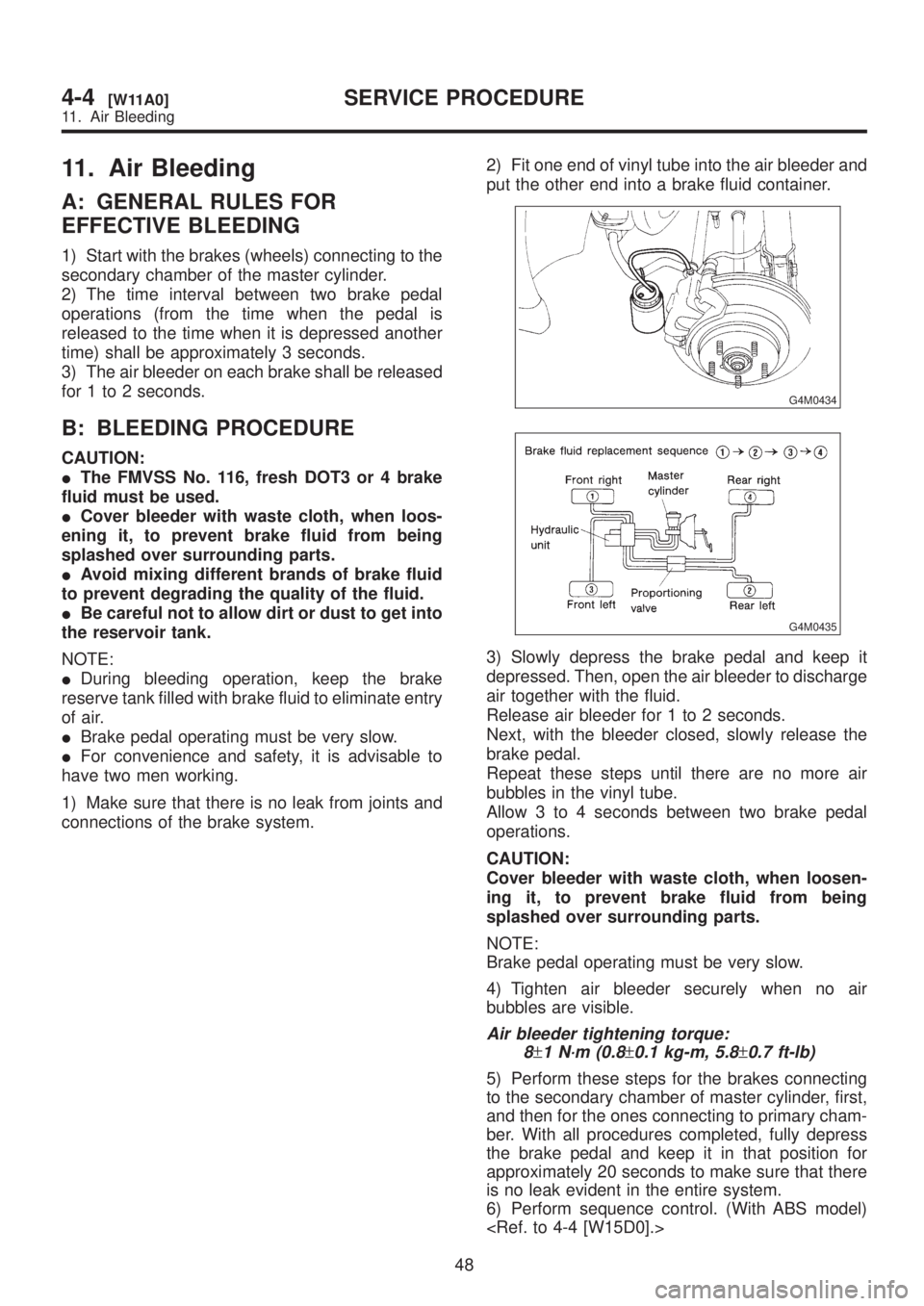
connections of the brake system.2) Fit one end of vinyl tube into the air bleeder and
put the other end into a brake fluid container.
G4M0434
G4M0435
3) Slowly depress the brake pedal and keep it
depressed. Then, open the air bleeder to discharge
air together with the fluid.
Release air bleeder for 1 to 2 seconds.
Next, with the bleeder closed, slowly release the
brake pedal.
Repeat these steps until there are no more air
bubbles in the vinyl tube.
Allow 3 to 4 seconds between two brake pedal
operations.
CAUTION:
Cover bleeder with waste cloth, when loosen-
ing it, to prevent brake fluid from being
splashed over surrounding parts.
NOTE:
Brake pedal operating must be very slow.
4) Tighten air bleeder securely when no air
bubbles are visible.
Air bleeder tightening torque:
8
±1 N´m (0.8±0.1 kg-m, 5.8±0.7 ft-lb)
5) Perform these steps for the brakes connecting
to the secondary chamber of master cylinder, first,
and then for the ones connecting to primary cham-
ber. With all procedures completed, fully depress
the brake pedal and keep it in that position for
approximately 20 seconds to make sure that there
is no leak evident in the entire system.
6) Perform sequence control. (With ABS model)
48
4-4[W11A0]SERVICE PROCEDURE
11. Air Bleeding
Page 925 of 1456
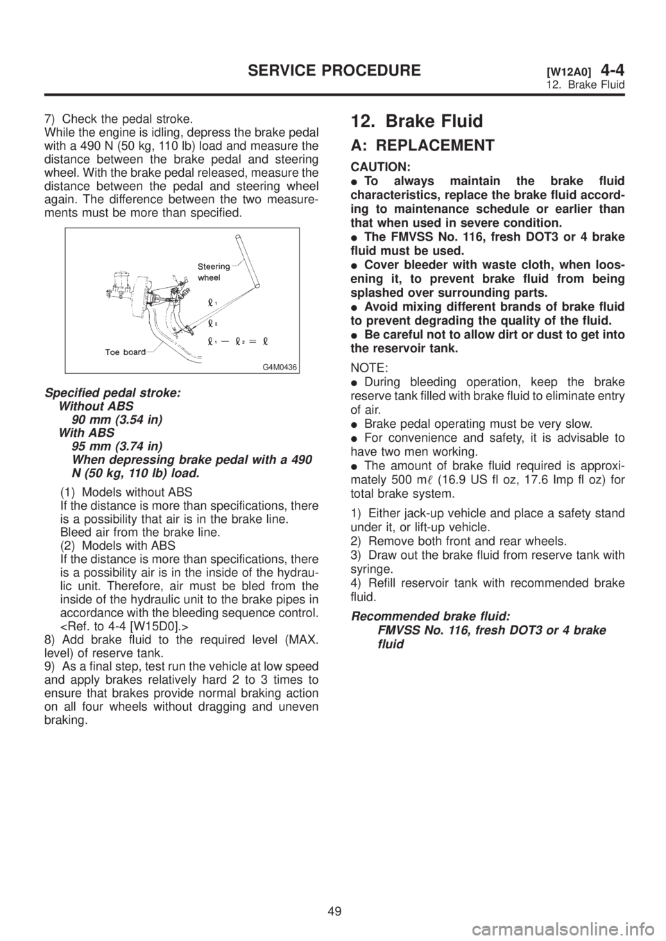
7) Check the pedal stroke.
While the engine is idling, depress the brake pedal
with a 490 N (50 kg, 110 lb) load and measure the
distance between the brake pedal and steering
wheel. With the brake pedal released, measure the
distance between the pedal and steering wheel
again. The difference between the two measure-
ments must be more than specified.
G4M0436
Specified pedal stroke:
Without ABS
90 mm (3.54 in)
With ABS
95 mm (3.74 in)
When depressing brake pedal with a 490
N (50 kg, 110 lb) load.
(1) Models without ABS
If the distance is more than specifications, there
is a possibility that air is in the brake line.
Bleed air from the brake line.
(2) Models with ABS
If the distance is more than specifications, there
is a possibility air is in the inside of the hydrau-
lic unit. Therefore, air must be bled from the
inside of the hydraulic unit to the brake pipes in
accordance with the bleeding sequence control.
8) Add brake fluid to the required level (MAX.
level) of reserve tank.
9) As a final step, test run the vehicle at low speed
and apply brakes relatively hard 2 to 3 times to
ensure that brakes provide normal braking action
on all four wheels without dragging and uneven
braking.
12. Brake Fluid
A: REPLACEMENT
CAUTION:
ITo always maintain the brake fluid
characteristics, replace the brake fluid accord-
ing to maintenance schedule or earlier than
that when used in severe condition.
IThe FMVSS No. 116, fresh DOT3 or 4 brake
fluid must be used.
ICover bleeder with waste cloth, when loos-
ening it, to prevent brake fluid from being
splashed over surrounding parts.
IAvoid mixing different brands of brake fluid
to prevent degrading the quality of the fluid.
IBe careful not to allow dirt or dust to get into
the reservoir tank.
NOTE:
IDuring bleeding operation, keep the brake
reserve tank filled with brake fluid to eliminate entry
of air.
IBrake pedal operating must be very slow.
IFor convenience and safety, it is advisable to
have two men working.
IThe amount of brake fluid required is approxi-
mately 500 m(16.9 US fl oz, 17.6 Imp fl oz) for
total brake system.
1) Either jack-up vehicle and place a safety stand
under it, or lift-up vehicle.
2) Remove both front and rear wheels.
3) Draw out the brake fluid from reserve tank with
syringe.
4) Refill reservoir tank with recommended brake
fluid.
Recommended brake fluid:
FMVSS No. 116, fresh DOT3 or 4 brake
fluid
49
[W12A0]4-4SERVICE PROCEDURE
12. Brake Fluid