1999 SUBARU LEGACY specifications
[x] Cancel search: specificationsPage 36 of 1456
![SUBARU LEGACY 1999 Service Repair Manual CAUTION:
Never rotate idle adjusting screw. If idle speed
is out of specifications, refer to General On-
board Diagnosis Table under ª2-7 On-Board
Diagnostics II Systemº.
<Ref. to 2-7 [T6A0].>4. Eng SUBARU LEGACY 1999 Service Repair Manual CAUTION:
Never rotate idle adjusting screw. If idle speed
is out of specifications, refer to General On-
board Diagnosis Table under ª2-7 On-Board
Diagnostics II Systemº.
<Ref. to 2-7 [T6A0].>4. Eng](/manual-img/17/57435/w960_57435-35.png)
CAUTION:
Never rotate idle adjusting screw. If idle speed
is out of specifications, refer to General On-
board Diagnosis Table under ª2-7 On-Board
Diagnostics II Systemº.
A: MEASUREMENT
1. 2200 cc MODEL
1) After warming-up the engine, turn ignition
switch to OFF.
2) Make sure that the battery is fully charged.
3) Remove all the spark plugs.
4) Disconnect connectors from fuel injectors.
5) Fully open throttle valve.
6) Check the starter motor for satisfactory perfor-
mance and operation.
7) Hold the compression gauge tight against the
spark plug hole.
CAUTION:
When using a screw-in type compression
gauge, the screw (put into cylinder head spark
plug hole) should be less than 18 mm (0.71 in)
long.
8) Crank the engine by means of the starter motor,
and read the maximum value on the gauge when
the pointer is steady.
G2M0098
9) Perform at least two measurements per
cylinder, and make sure that the values are correct.
Compression (200 Ð 300 rpm and fully open
throttle):
Standard;
1,079 Ð 1,275 kPa (11.0 Ð 13.0 kg/cm
2,
156 Ð 185 psi)
Limit;
883 kPa (9.0 kg/cm
2, 128 psi)
Difference between cylinders;
196 kPa (2.0 kg/cm
2, 28 psi)
4
2-2[W4A1]SERVICE PROCEDURE
4. Engine Compression
Page 37 of 1456
![SUBARU LEGACY 1999 Service Repair Manual CAUTION:
Never rotate idle adjusting screw. If idle speed
is out of specifications, refer to General On-
board Diagnosis Table under ª2-7 On-Board
Diagnostics II Systemº.
<Ref. to 2-7 [T6A0].>4. Eng SUBARU LEGACY 1999 Service Repair Manual CAUTION:
Never rotate idle adjusting screw. If idle speed
is out of specifications, refer to General On-
board Diagnosis Table under ª2-7 On-Board
Diagnostics II Systemº.
<Ref. to 2-7 [T6A0].>4. Eng](/manual-img/17/57435/w960_57435-36.png)
CAUTION:
Never rotate idle adjusting screw. If idle speed
is out of specifications, refer to General On-
board Diagnosis Table under ª2-7 On-Board
Diagnostics II Systemº.
A: MEASUREMENT
1. 2200 cc MODEL
1) After warming-up the engine, turn ignition
switch to OFF.
2) Make sure that the battery is fully charged.
3) Remove all the spark plugs.
4) Disconnect connectors from fuel injectors.
5) Fully open throttle valve.
6) Check the starter motor for satisfactory perfor-
mance and operation.
7) Hold the compression gauge tight against the
spark plug hole.
CAUTION:
When using a screw-in type compression
gauge, the screw (put into cylinder head spark
plug hole) should be less than 18 mm (0.71 in)
long.
8) Crank the engine by means of the starter motor,
and read the maximum value on the gauge when
the pointer is steady.
G2M0098
9) Perform at least two measurements per
cylinder, and make sure that the values are correct.
Compression (200 Ð 300 rpm and fully open
throttle):
Standard;
1,079 Ð 1,275 kPa (11.0 Ð 13.0 kg/cm
2,
156 Ð 185 psi)
Limit;
883 kPa (9.0 kg/cm
2, 128 psi)
Difference between cylinders;
196 kPa (2.0 kg/cm
2, 28 psi)
4
2-2[W4A1]SERVICE PROCEDURE
4. Engine Compression
Page 54 of 1456

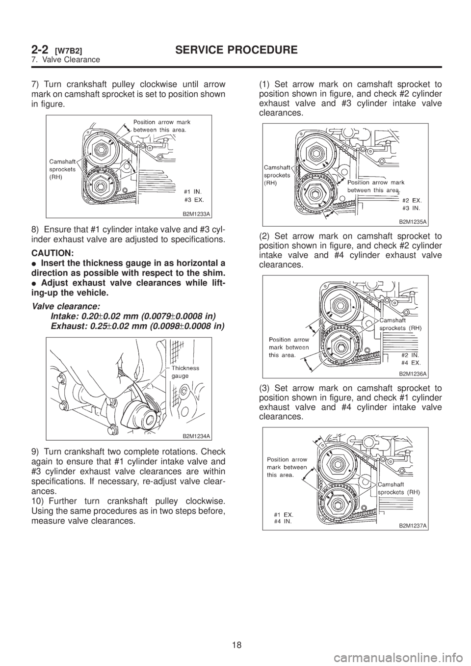
7) Turn crankshaft pulley clockwise until arrow
mark on camshaft sprocket is set to position shown
in figure.
B2M1233A
8) Ensure that #1 cylinder intake valve and #3 cyl-
inder exhaust valve are adjusted to specifications.
CAUTION:
IInsert the thickness gauge in as horizontal a
direction as possible with respect to the shim.
IAdjust exhaust valve clearances while lift-
ing-up the vehicle.
Valve clearance:
Intake: 0.20
±0.02 mm (0.0079±0.0008 in)
Exhaust: 0.25
±0.02 mm (0.0098±0.0008 in)
B2M1234A
9) Turn crankshaft two complete rotations. Check
again to ensure that #1 cylinder intake valve and
#3 cylinder exhaust valve clearances are within
specifications. If necessary, re-adjust valve clear-
ances.
10) Further turn crankshaft pulley clockwise.
Using the same procedures as in two steps before,
measure valve clearances.(1) Set arrow mark on camshaft sprocket to
position shown in figure, and check #2 cylinder
exhaust valve and #3 cylinder intake valve
clearances.
B2M1235A
(2) Set arrow mark on camshaft sprocket to
position shown in figure, and check #2 cylinder
intake valve and #4 cylinder exhaust valve
clearances.
B2M1236A
(3) Set arrow mark on camshaft sprocket to
position shown in figure, and check #1 cylinder
exhaust valve and #4 cylinder intake valve
clearances.
B2M1237A
18
2-2[W7B2]SERVICE PROCEDURE
7. Valve Clearance
Page 55 of 1456

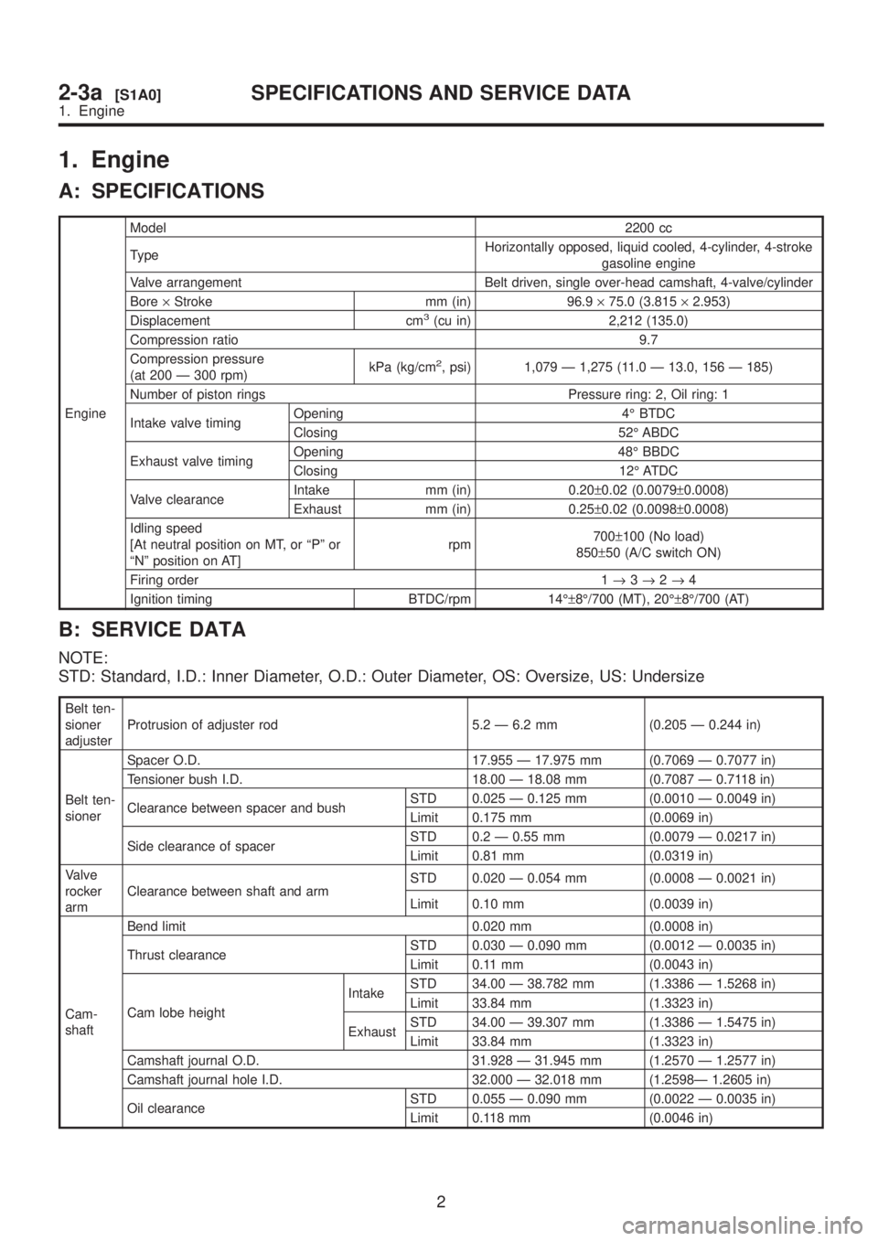
1. Engine
A: SPECIFICATIONS
EngineModel2200 cc
TypeHorizontally opposed, liquid cooled, 4-cylinder, 4-stroke
gasoline engine
Valve arrangement Belt driven, single over-head camshaft, 4-valve/cylinder
Bore´Stroke mm (in) 96.9´75.0 (3.815´2.953)
Displacement cm
3(cu in) 2,212 (135.0)
Compression ratio 9.7
Compression pressure
(at 200 Ð 300 rpm)kPa (kg/cm
2, psi) 1,079 Ð 1,275 (11.0 Ð 13.0, 156 Ð 185)
Number of piston rings Pressure ring: 2, Oil ring: 1
Intake valve timingOpening 4É BTDC
Closing 52É ABDC
Exhaust valve timingOpening 48É BBDC
Closing 12É ATDC
Valve clearanceIntake mm (in) 0.20±0.02 (0.0079±0.0008)
Exhaust mm (in) 0.25±0.02 (0.0098±0.0008)
Idling speed
[At neutral position on MT, or ªPº or
ªNº position on AT]rpm700±100 (No load)
850±50 (A/C switch ON)
Firing order 1®3®2®4
Ignition timing BTDC/rpm 14ɱ8É/700 (MT), 20ɱ8É/700 (AT)
B: SERVICE DATA
NOTE:
STD: Standard, I.D.: Inner Diameter, O.D.: Outer Diameter, OS: Oversize, US: Undersize
Belt ten-
sioner
adjusterProtrusion of adjuster rod 5.2 Ð 6.2 mm (0.205 Ð 0.244 in)
Belt ten-
sionerSpacer O.D. 17.955 Ð 17.975 mm (0.7069 Ð 0.7077 in)
Tensioner bush I.D. 18.00 Ð 18.08 mm (0.7087 Ð 0.7118 in)
Clearance between spacer and bushSTD 0.025 Ð 0.125 mm (0.0010 Ð 0.0049 in)
Limit 0.175 mm (0.0069 in)
Side clearance of spacerSTD 0.2 Ð 0.55 mm (0.0079 Ð 0.0217 in)
Limit 0.81 mm (0.0319 in)
Valve
rocker
armClearance between shaft and armSTD 0.020 Ð 0.054 mm (0.0008 Ð 0.0021 in)
Limit 0.10 mm (0.0039 in)
Cam-
shaftBend limit 0.020 mm (0.0008 in)
Thrust clearanceSTD 0.030 Ð 0.090 mm (0.0012 Ð 0.0035 in)
Limit 0.11 mm (0.0043 in)
Cam lobe heightIntakeSTD 34.00 Ð 38.782 mm (1.3386 Ð 1.5268 in)
Limit 33.84 mm (1.3323 in)
ExhaustSTD 34.00 Ð 39.307 mm (1.3386 Ð 1.5475 in)
Limit 33.84 mm (1.3323 in)
Camshaft journal O.D. 31.928 Ð 31.945 mm (1.2570 Ð 1.2577 in)
Camshaft journal hole I.D. 32.000 Ð 32.018 mm (1.2598Ð 1.2605 in)
Oil clearanceSTD 0.055 Ð 0.090 mm (0.0022 Ð 0.0035 in)
Limit 0.118 mm (0.0046 in)
2
2-3a[S1A0]SPECIFICATIONS AND SERVICE DATA
1. Engine
Page 56 of 1456

Cylinder
headSurface warpage limit 0.05 mm (0.0020 in)
Surface grinding limit 0.3 mm (0.012 in)
Standard height 97.5 mm (3.839 in)
Valve
setRefacing angle 90É
Contacting widthIntakeSTD 1.0 mm (0.039 in)
Limit 1.7 mm (0.067 in)
ExhaustSTD 1.4 mm (0.055 in)
Limit 2.1 mm (0.083 in)
Valve
guideInner diameter 6.000 Ð 6.012 mm (0.2362 Ð 0.2367 in)
Protrusion above headIntake 20.0 Ð 20.5 mm (0.787 Ð 0.807 in)
Exhaust 16.5 Ð 17.0 mm (0.650 Ð 0.669 in)
ValveHead edge thicknessIntakeSTD 1.0 mm (0.039 in)
Limit 0.6 mm (0.024 in)
ExhaustSTD 1.2 mm (0.047 in)
Limit 0.6 mm (0.024 in)
Stem diameterIntake 5.945 Ð 5.960 mm (0.2341 Ð 0.2346 in)
Exhaust 5.950 Ð 5.965 mm (0.2343 Ð 0.2348 in)
Stem oil clearanceSTDIntake 0.035 Ð 0.062 mm (0.0014 Ð 0.0024 in)
Exhaust 0.040 Ð 0.067 mm (0.0016 Ð 0.0026 in)
Limit Ð 0.15 mm (0.0059 in)
Overall lengthIntake 120.6 mm (4.75 in)
Exhaust 121.7 mm (4.79 in)
Valve
springFree length 54.30 mm (2.1378 in)
Squareness 2.5É, 2.4 mm (0.094 in)
Tension/spring height214.8 Ð 246.2 N
(21.9 Ð 25.1 kg, 48.3 Ð 55.3 lb)/45.0 mm (1.772 in)
526.6 Ð 581.6 N
(53.7 Ð 59.3 kg, 118.4 Ð 130.8 lb)/34.7 mm (1.366 in)
Cylinder
blockSurface warpage limit (mating with cylinder head) 0.05 mm (0.0020 in)
Surface grinding limit 0.1 mm (0.004 in)
Cylinder bore STDA 96.905 Ð 96.915 mm (3.8151 Ð 3.8155 in)
B 96.895 Ð 96.905 mm (3.8148 Ð 3.8151 in)
TaperSTD 0.015 mm (0.0006 in)
Limit 0.050 mm (0.0020 in)
Out-of-roundnessSTD 0.010 mm (0.0004 in)
Limit 0.050 mm (0.0020 in)
Piston clearanceSTD 0.010 Ð 0.030 mm (0.0004 Ð 0.0012 in)
Limit 0.050 mm (0.0020 in)
Enlarging (boring) limit 0.5 mm (0.020 in)
Piston Outer diameterSTDA 96.885 Ð 96.895 mm (3.8144 Ð 3.8148 in)
B 96.875 Ð 96.885 mm (3.8140 Ð 3.8144 in)
0.25 mm (0.0098
in) OS97.125 Ð 97.135 mm (3.8238 Ð 3.8242 in)
0.50 mm (0.0197
in) OS97.375 Ð 97.385 mm (3.8337 Ð 3.8340 in)
Piston
pinStandard clearance between piston
pin and hole in pistonSTD 0.004 Ð 0.008 mm (0.0002 Ð 0.0003 in)
Limit 0.020 mm (0.0008 in)
Degree of fitPiston pin must be fitted into position with thumb at 20ÉC
(68ÉF).
3
[S1B0]2-3aSPECIFICATIONS AND SERVICE DATA
1. Engine
Page 57 of 1456

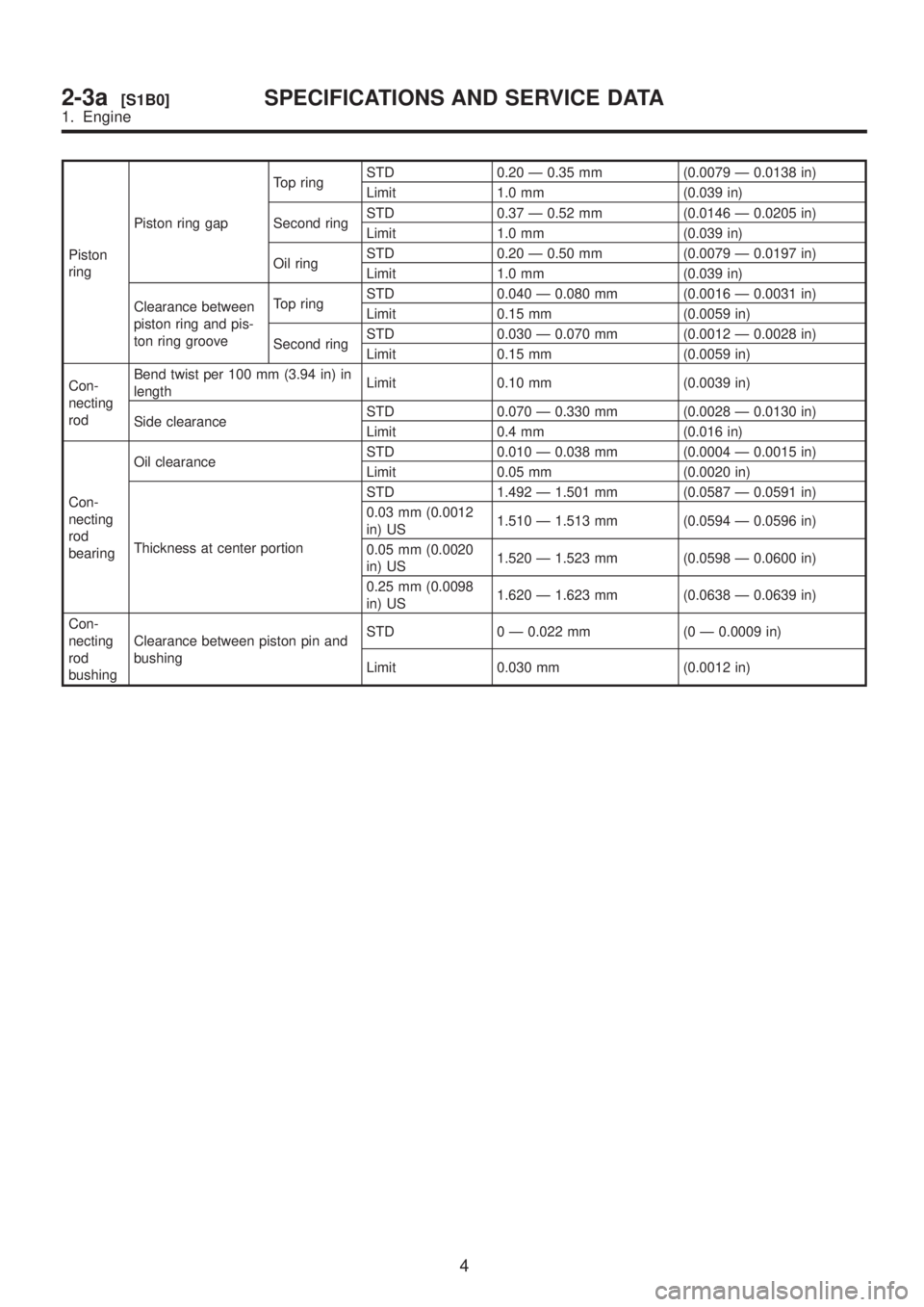
Piston
ringPiston ring gapTop ringSTD 0.20 Ð 0.35 mm (0.0079 Ð 0.0138 in)
Limit 1.0 mm (0.039 in)
Second ringSTD 0.37 Ð 0.52 mm (0.0146 Ð 0.0205 in)
Limit 1.0 mm (0.039 in)
Oil ringSTD 0.20 Ð 0.50 mm (0.0079 Ð 0.0197 in)
Limit 1.0 mm (0.039 in)
Clearance between
piston ring and pis-
ton ring grooveTop ringSTD 0.040 Ð 0.080 mm (0.0016 Ð 0.0031 in)
Limit 0.15 mm (0.0059 in)
Second ringSTD 0.030 Ð 0.070 mm (0.0012 Ð 0.0028 in)
Limit 0.15 mm (0.0059 in)
Con-
necting
rodBend twist per 100 mm (3.94 in) in
lengthLimit 0.10 mm (0.0039 in)
Side clearanceSTD 0.070 Ð 0.330 mm (0.0028 Ð 0.0130 in)
Limit 0.4 mm (0.016 in)
Con-
necting
rod
bearingOil clearanceSTD 0.010 Ð 0.038 mm (0.0004 Ð 0.0015 in)
Limit 0.05 mm (0.0020 in)
Thickness at center portionSTD 1.492 Ð 1.501 mm (0.0587 Ð 0.0591 in)
0.03 mm (0.0012
in) US1.510 Ð 1.513 mm (0.0594 Ð 0.0596 in)
0.05 mm (0.0020
in) US1.520 Ð 1.523 mm (0.0598 Ð 0.0600 in)
0.25 mm (0.0098
in) US1.620 Ð 1.623 mm (0.0638 Ð 0.0639 in)
Con-
necting
rod
bushingClearance between piston pin and
bushingSTD 0 Ð 0.022 mm (0 Ð 0.0009 in)
Limit 0.030 mm (0.0012 in)
4
2-3a[S1B0]SPECIFICATIONS AND SERVICE DATA
1. Engine
Page 58 of 1456

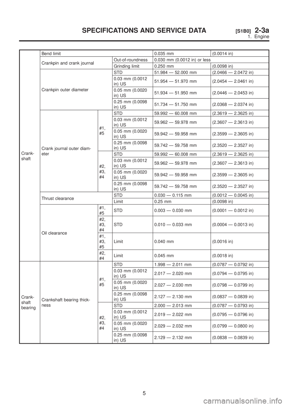
Crank-
shaftBend limit 0.035 mm (0.0014 in)
Crankpin and crank journalOut-of-roundness 0.030 mm (0.0012 in) or less
Grinding limit 0.250 mm (0.0098 in)
Crankpin outer diameterSTD 51.984 Ð 52.000 mm (2.0466 Ð 2.0472 in)
0.03 mm (0.0012
in) US51.954 Ð 51.970 mm (2.0454 Ð 2.0461 in)
0.05 mm (0.0020
in) US51.934 Ð 51.950 mm (2.0446 Ð 2.0453 in)
0.25 mm (0.0098
in) US51.734 Ð 51.750 mm (2.0368 Ð 2.0374 in)
Crank journal outer diam-
eter#1,
#5STD 59.992 Ð 60.008 mm (2.3619 Ð 2.3625 in)
0.03 mm (0.0012
in) US59.962 Ð 59.978 mm (2.3607 Ð 2.3613 in)
0.05 mm (0.0020
in) US59.942 Ð 59.958 mm (2.3599 Ð 2.3605 in)
0.25 mm (0.0098
in) US59.742 Ð 59.758 mm (2.3520 Ð 2.3527 in)
#2,
#3,
#4STD 59.992 Ð 60.008 mm (2.3619 Ð 2.3625 in)
0.03 mm (0.0012
in) US59.962 Ð 59.978 mm (2.3607 Ð 2.3613 in)
0.05 mm (0.0020
in) US59.942 Ð 59.958 mm (2.3599 Ð 2.3605 in)
0.25 mm (0.0098
in) US59.742 Ð 59.758 mm (2.3520 Ð 2.3527 in)
Thrust clearanceSTD 0.030 Ð 0.115 mm (0.0012 Ð 0.0045 in)
Limit 0.25 mm (0.0098 in)
Oil clearance#1,
#5STD 0.003 Ð 0.030 mm (0.0001 Ð 0.0012 in)
#2,
#3,
#4STD 0.010 Ð 0.033 mm (0.0004 Ð 0.0013 in)
#1,
#3,
#5Limit 0.040 mm (0.0016 in)
#2,
#4Limit 0.045 mm (0.0018 in)
Crank-
shaft
bearingCrankshaft bearing thick-
ness#1,
#5STD 1.998 Ð 2.011 mm (0.0787 Ð 0.0792 in)
0.03 mm (0.0012
in) US2.017 Ð 2.020 mm (0.0794 Ð 0.0795 in)
0.05 mm (0.0020
in) US2.027 Ð 2.030 mm (0.0798 Ð 0.0799 in)
0.25 mm (0.0098
in) US2.127 Ð 2.130 mm (0.0837 Ð 0.0839 in)
#2,
#3,
#4STD 2.000 Ð 2.013 mm (0.0787 Ð 0.0793 in)
0.03 mm (0.0012
in) US2.019 Ð 2.022 mm (0.0795 Ð 0.0796 in)
0.05 mm (0.0020
in) US2.029 Ð 2.032 mm (0.0799 Ð 0.0800 in)
0.25 mm (0.0098
in) US2.129 Ð 2.132 mm (0.0838 Ð 0.0839 in)
5
[S1B0]2-3aSPECIFICATIONS AND SERVICE DATA
1. Engine
Page 72 of 1456

IPress-in the push adjuster rod gradually tak-
ing more than three minutes.
IDo not allow press pressure to exceed 9,807
N (1,000 kg, 2,205 lb).
IPress the adjuster rod as far as the end sur-
face of the cylinder. Do not press the adjuster
rod into the cylinder. Doing so may damage the
cylinder.
4) Measure the extension of rod beyond the body.
If it is not within specifications, replace with a new
one.
Rod extension: H
5.7
±0.5 mm (0.224±0.020 in)
H2M2381A
3. BELT TENSION PULLEY
1) Check mating surfaces of timing belt and con-
tact point of adjuster rod for abnormal wear or
scratches. Replace automatic belt tension adjuster
assembly if faulty.
2) Check tension pulley for smooth rotation.
Replace if noise or excessive play is noted.
3) Check tension pulley for grease leakage.
4. BELT IDLER
1) Check belt idler for smooth rotation. Replace if
noise or excessive play is noted.
2) Check belt outer contacting surfaces of idler
pulley for abnormal wear and scratches.
3) Check belt idler for grease leakage.
5. CAMSHAFT AND CRANKSHAFT
SPROCKET
1) Check sprocket teeth for abnormal wear and
scratches.
2) Make sure there is no free play between
sprocket and key.
3) Check crankshaft sprocket notch for sensor for
damage and contamination of foreign matter.
C: INSTALLATION
1. CAMSHAFT AND CRANKSHAFT SPROCKET
B2M2598A
(1) Tensioner bracket
(2) Belt cover No. 2 (RH)
(3) Belt cover No. 2 (LH)
(4) Crankshaft sprocket(5) Camshaft sprocket No. 1
(6) Camshaft sprocket No. 2Tightening torque: N´m (kg-m, ft-lb)
T1:
5±1 (0.5±0.1, 3.6±0.7)
T2:25±3 (2.5±0.3, 18.1±2.2)
T3:78±5 (8.0±0.5, 57.9±3.6)
19
[W2C1]2-3aSERVICE PROCEDURE
2. Timing Belt