Page 470 of 1456

6. Shifter Fork And Rod
Select suitable shifter forks so that both coupling
sleeve and reverse driven gear are positioned in
the center of their synchromesh mechanisms.
1st-2nd shifter fork
Part No. Mark Remarks
32804AA060 1Approach to 1st gear
by 0.2 mm (0.008 in)
32804AA070 No mark Standard
32804AA080 3Approach to 2nd gear
by 0.2 mm (0.008 in)
3rd-4th shifter fork
Part No. Mark Remarks
32810AA061 1Approach to 4th gear
by 0.2 mm (0.008 in)
32810AA071 No mark Standard
32810AA101 3Approach to 3rd gear
by 0.2 mm (0.008 in)
5th shifter fork
Part No. Mark Remarks
32812AA200 1Approach to 5th gear
by 0.2 mm (0.008 in)
32812AA210 No mark Standard
32812AA220 3Become distant from
5th gear by 0.2 mm
(0.008 in)
Rod end clearance
A: 1st-2nd Ð 3rd-4th
0.5 Ð 1.5 mm (0.020 Ð 0.059 in)
B: 3rd-4th Ð 5th
0.6 Ð 1.4 mm (0.024 Ð 0.055 in)
7. Transfer Case
Neutral position adjustment
Adjustment shim
Part No. Thickness mm (in)
32190AA000 0.15 (0.0059)
32190AA010 0.30 (0.0118)
Reverse accent shaft
Part No. Mark Remarks
32188AA090 XNeutral position is
closer to 1st.
32188AA100 Y Standard
32188AA110 ZNeutral position is
closer to reverse
gear.
Reverse check plate adjustment
Reverse check plate
Part No. Mark AngleqRemarks
32189AA000 0 28ÉArm stops closer to
5th gear.
32189AA010 1 31ÉArm stops closer to
5th gear.
33189AA020 2 34ÉArm stops in the cen-
ter.
32189AA030 3 37ÉArm stops closer to
reverse gear.
32189AA040 4 40ÉArm stops closer to
reverse gear.
4
3-1[S600]SPECIFICATIONS AND SERVICE DATA
6. Shifter Fork And Rod
Page 471 of 1456

6. Shifter Fork And Rod
Select suitable shifter forks so that both coupling
sleeve and reverse driven gear are positioned in
the center of their synchromesh mechanisms.
1st-2nd shifter fork
Part No. Mark Remarks
32804AA060 1Approach to 1st gear
by 0.2 mm (0.008 in)
32804AA070 No mark Standard
32804AA080 3Approach to 2nd gear
by 0.2 mm (0.008 in)
3rd-4th shifter fork
Part No. Mark Remarks
32810AA061 1Approach to 4th gear
by 0.2 mm (0.008 in)
32810AA071 No mark Standard
32810AA101 3Approach to 3rd gear
by 0.2 mm (0.008 in)
5th shifter fork
Part No. Mark Remarks
32812AA200 1Approach to 5th gear
by 0.2 mm (0.008 in)
32812AA210 No mark Standard
32812AA220 3Become distant from
5th gear by 0.2 mm
(0.008 in)
Rod end clearance
A: 1st-2nd Ð 3rd-4th
0.5 Ð 1.5 mm (0.020 Ð 0.059 in)
B: 3rd-4th Ð 5th
0.6 Ð 1.4 mm (0.024 Ð 0.055 in)
7. Transfer Case
Neutral position adjustment
Adjustment shim
Part No. Thickness mm (in)
32190AA000 0.15 (0.0059)
32190AA010 0.30 (0.0118)
Reverse accent shaft
Part No. Mark Remarks
32188AA090 XNeutral position is
closer to 1st.
32188AA100 Y Standard
32188AA110 ZNeutral position is
closer to reverse
gear.
Reverse check plate adjustment
Reverse check plate
Part No. Mark AngleqRemarks
32189AA000 0 28ÉArm stops closer to
5th gear.
32189AA010 1 31ÉArm stops closer to
5th gear.
33189AA020 2 34ÉArm stops in the cen-
ter.
32189AA030 3 37ÉArm stops closer to
reverse gear.
32189AA040 4 40ÉArm stops closer to
reverse gear.
4
3-1[S600]SPECIFICATIONS AND SERVICE DATA
6. Shifter Fork And Rod
Page 472 of 1456

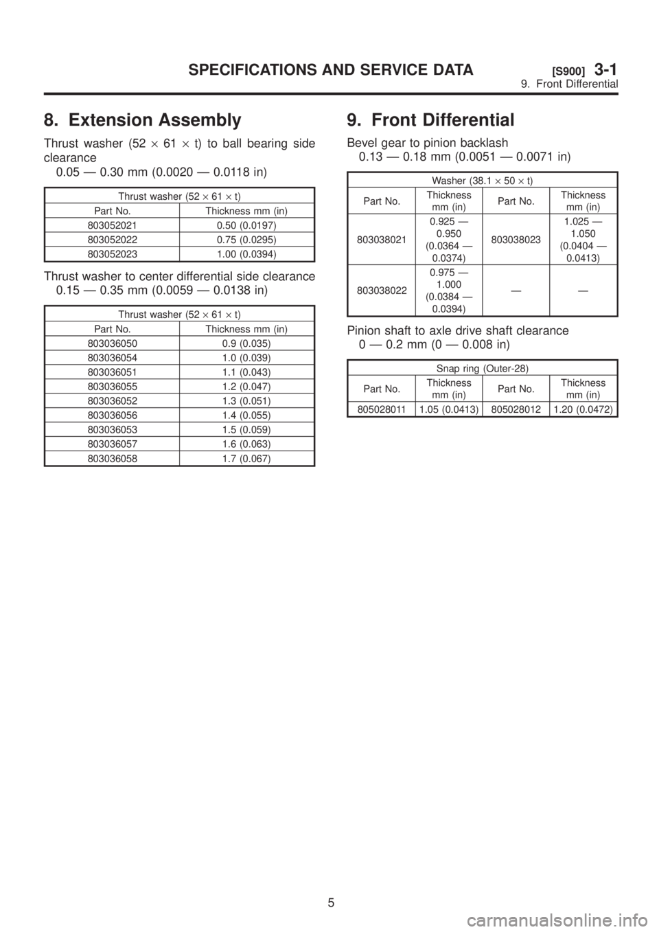
8. Extension Assembly
Thrust washer (52´61´t) to ball bearing side
clearance
0.05 Ð 0.30 mm (0.0020 Ð 0.0118 in)
Thrust washer (52´61´t)
Part No. Thickness mm (in)
803052021 0.50 (0.0197)
803052022 0.75 (0.0295)
803052023 1.00 (0.0394)
Thrust washer to center differential side clearance
0.15 Ð 0.35 mm (0.0059 Ð 0.0138 in)
Thrust washer (52´61´t)
Part No. Thickness mm (in)
803036050 0.9 (0.035)
803036054 1.0 (0.039)
803036051 1.1 (0.043)
803036055 1.2 (0.047)
803036052 1.3 (0.051)
803036056 1.4 (0.055)
803036053 1.5 (0.059)
803036057 1.6 (0.063)
803036058 1.7 (0.067)
9. Front Differential
Bevel gear to pinion backlash
0.13 Ð 0.18 mm (0.0051 Ð 0.0071 in)
Washer (38.1´50´t)
Part No.Thickness
mm (in)Part No.Thickness
mm (in)
8030380210.925 Ð
0.950
(0.0364 Ð
0.0374)8030380231.025 Ð
1.050
(0.0404 Ð
0.0413)
8030380220.975 Ð
1.000
(0.0384 Ð
0.0394)ÐÐ
Pinion shaft to axle drive shaft clearance
0 Ð 0.2 mm (0 Ð 0.008 in)
Snap ring (Outer-28)
Part No.Thickness
mm (in)Part No.Thickness
mm (in)
805028011 1.05 (0.0413) 805028012 1.20 (0.0472)
5
[S900]3-1SPECIFICATIONS AND SERVICE DATA
9. Front Differential
Page 473 of 1456

8. Extension Assembly
Thrust washer (52´61´t) to ball bearing side
clearance
0.05 Ð 0.30 mm (0.0020 Ð 0.0118 in)
Thrust washer (52´61´t)
Part No. Thickness mm (in)
803052021 0.50 (0.0197)
803052022 0.75 (0.0295)
803052023 1.00 (0.0394)
Thrust washer to center differential side clearance
0.15 Ð 0.35 mm (0.0059 Ð 0.0138 in)
Thrust washer (52´61´t)
Part No. Thickness mm (in)
803036050 0.9 (0.035)
803036054 1.0 (0.039)
803036051 1.1 (0.043)
803036055 1.2 (0.047)
803036052 1.3 (0.051)
803036056 1.4 (0.055)
803036053 1.5 (0.059)
803036057 1.6 (0.063)
803036058 1.7 (0.067)
9. Front Differential
Bevel gear to pinion backlash
0.13 Ð 0.18 mm (0.0051 Ð 0.0071 in)
Washer (38.1´50´t)
Part No.Thickness
mm (in)Part No.Thickness
mm (in)
8030380210.925 Ð
0.950
(0.0364 Ð
0.0374)8030380231.025 Ð
1.050
(0.0404 Ð
0.0413)
8030380220.975 Ð
1.000
(0.0384 Ð
0.0394)ÐÐ
Pinion shaft to axle drive shaft clearance
0 Ð 0.2 mm (0 Ð 0.008 in)
Snap ring (Outer-28)
Part No.Thickness
mm (in)Part No.Thickness
mm (in)
805028011 1.05 (0.0413) 805028012 1.20 (0.0472)
5
[S900]3-1SPECIFICATIONS AND SERVICE DATA
9. Front Differential
Page 493 of 1456

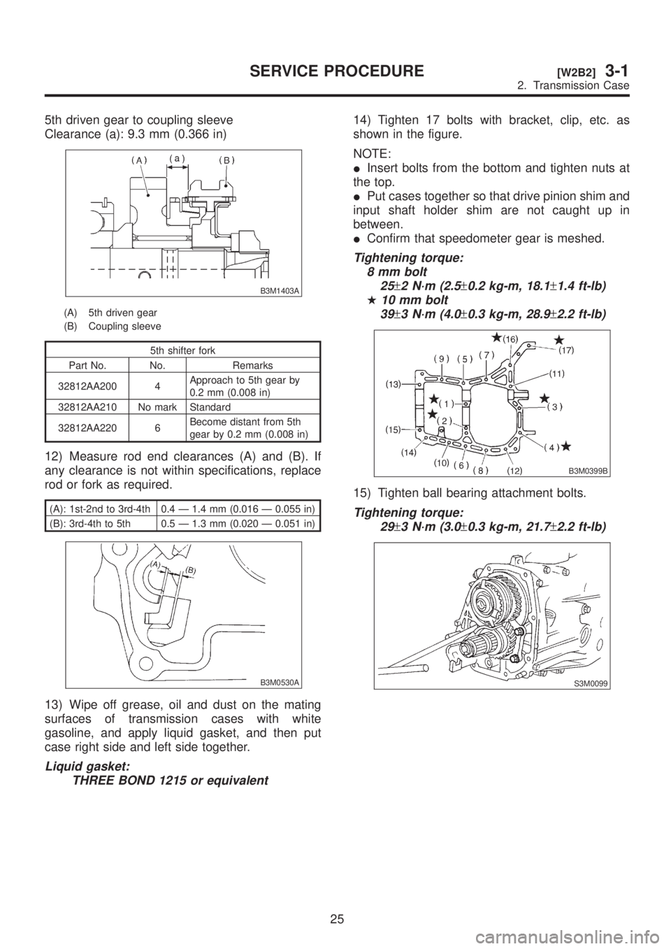
5th driven gear to coupling sleeve
Clearance (a): 9.3 mm (0.366 in)
B3M1403A
(A) 5th driven gear
(B) Coupling sleeve
5th shifter fork
Part No. No. Remarks
32812AA200 4Approach to 5th gear by
0.2 mm (0.008 in)
32812AA210 No mark Standard
32812AA220 6Become distant from 5th
gear by 0.2 mm (0.008 in)
12) Measure rod end clearances (A) and (B). If
any clearance is not within specifications, replace
rod or fork as required.
(A): 1st-2nd to 3rd-4th 0.4 Ð 1.4 mm (0.016 Ð 0.055 in)
(B): 3rd-4th to 5th 0.5 Ð 1.3 mm (0.020 Ð 0.051 in)
B3M0530A
13) Wipe off grease, oil and dust on the mating
surfaces of transmission cases with white
gasoline, and apply liquid gasket, and then put
case right side and left side together.
Liquid gasket:
THREE BOND 1215 or equivalent
14) Tighten 17 bolts with bracket, clip, etc. as
shown in the figure.
NOTE:
IInsert bolts from the bottom and tighten nuts at
the top.
IPut cases together so that drive pinion shim and
input shaft holder shim are not caught up in
between.
IConfirm that speedometer gear is meshed.
Tightening torque:
8 mm bolt
25
±2 N´m (2.5±0.2 kg-m, 18.1±1.4 ft-lb)
H10 mm bolt
39
±3 N´m (4.0±0.3 kg-m, 28.9±2.2 ft-lb)
B3M0399B
15) Tighten ball bearing attachment bolts.
Tightening torque:
29
±3 N´m (3.0±0.3 kg-m, 21.7±2.2 ft-lb)
S3M0099
25
[W2B2]3-1SERVICE PROCEDURE
2. Transmission Case
Page 521 of 1456

2) Measure backlash between bevel gear and pin-
ion. If it is not within specifications, install a suitable
washer to adjust it.
NOTE:
Be sure the pinion gear tooth contacts adjacent
gear teeth during measurement.
ST1 498247001 MAGNET BASE
ST2 498247100 DIAL GAUGE
Standard backlash:
0.13 Ð 0.18 mm (0.0051 Ð 0.0071 in)
G3M0670
Washer (38.1´50´t)
Part No. Thickness mm (in)
8030380210.925 Ð 0.950
(0.0364 Ð 0.0374)
8030380220.975 Ð 1.000
(0.0384 Ð 0.0394)
8030380231.025 Ð 1.050
(0.0404 Ð 0.0413)
3) Align pinion shaft and differential case at their
holes, and drive straight pin into holes from the
hypoid driven gear side, using ST.
NOTE:
Lock straight pin after installing.
ST 899904100 REMOVER
B3M0609C
(A) Pinion shaft
(B) Differential case
(C) Straight pin
4) Install roller bearing (40´80´19.75) to differ-
ential case.
NOTE:
Be careful because roller bearing outer races are
used as a set.
ST1 499277100 BUSH 1-2 INSTALLER
ST2 398497701 ADAPTER
G3M0671
5) Install hypoid driven gear to differential case
using twelve bolts.
Tightening torque:
T: 6 2
±5 N´m (6.3±0.5 kg-m, 45.6±3.6 ft-lb)
B3M0554C
(A) Hypoid driven gear
(B) Differential case
50
3-1[W6B0]SERVICE PROCEDURE
6. Front Differential
Page 522 of 1456
6) Position drive axle shaft in differential case and
hold it with outer snap ring (28). Using a thickness
gauge, measure clearance between the shaft and
case is within specifications.
NOTE:
If it is not within specifications, replace snap ring
with a suitable one.
Clearance:
0 Ð 0.2 mmm (0 Ð 0.008 in)
B3M0100
Snap ring (Outer-28)
Part No. Thickness mm (in)
805028011 1.05 (0.0413)
805028012 1.20 (0.0472)
7. Center Differential
A: DISASSEMBLY AND ASSEMBLY
1) Remove ball bearing using ST.
CAUTION:
Do not reuse ball bearing.
ST 498077300 CENTER DIFFERENTIAL
BEARING REMOVER
B3M1398A
2) Install ball bearing to center differential assem-
bly.
NOTE:
Do not disassemble center differential because it is
a non-disassemble part.
B3M1399A
51
[W7A0]3-1SERVICE PROCEDURE
7. Center Differential
Page 523 of 1456
6) Position drive axle shaft in differential case and
hold it with outer snap ring (28). Using a thickness
gauge, measure clearance between the shaft and
case is within specifications.
NOTE:
If it is not within specifications, replace snap ring
with a suitable one.
Clearance:
0 Ð 0.2 mmm (0 Ð 0.008 in)
B3M0100
Snap ring (Outer-28)
Part No. Thickness mm (in)
805028011 1.05 (0.0413)
805028012 1.20 (0.0472)
7. Center Differential
A: DISASSEMBLY AND ASSEMBLY
1) Remove ball bearing using ST.
CAUTION:
Do not reuse ball bearing.
ST 498077300 CENTER DIFFERENTIAL
BEARING REMOVER
B3M1398A
2) Install ball bearing to center differential assem-
bly.
NOTE:
Do not disassemble center differential because it is
a non-disassemble part.
B3M1399A
51
[W7A0]3-1SERVICE PROCEDURE
7. Center Differential