1999 SUBARU LEGACY wheel bolt torque
[x] Cancel search: wheel bolt torquePage 63 of 1456

5. Crankshaft and Piston
B2M1958A
(1) Flywheel (MT)
(2) Bell bearing (MT)
(3) Reinforcement (AT)
(4) Drive plate (AT)
(5) Top ring
(6) Second ring
(7) Oil ring
(8) Piston(9) Piston pin
(10) Circlip
(11) Connecting rod bolt
(12) Connecting rod
(13) Connecting rod bearing
(14) Connecting rod cap
(15) Crankshaft
(16) Woodruff key(17) Crankshaft bearing #1, #3
(18) Crankshaft bearing #2, #4
(19) Crankshaft bearing #5
Tightening torque: N´m (kg-m, ft-lb)
T1:
44±2 (4.5±0.2, 32.5±1.4)
T2:72±3 (7.3±0.3, 52.8±2.2)
10
2-3a[C500]COMPONENT PARTS
5. Crankshaft and Piston
Page 143 of 1456

5. Crankshaft and Piston
B2M1958A
(1) Flywheel (MT vehicles only)
(2) Bell bearing (MT vehicles only)
(3) Reinforcement (AT vehicles only)
(4) Drive plate (AT vehicles only)
(5) Top ring
(6) Second ring
(7) Oil ring
(8) Piston(9) Piston pin
(10) Circlip
(11) Connecting rod bolt
(12) Connecting rod
(13) Connecting rod bearing
(14) Connecting rod cap
(15) Crankshaft
(16) Woodruff key(17) Crankshaft bearing #1, #3
(18) Crankshaft bearing #2, #4
(19) Crankshaft bearing #5
Tightening torque: N´m (kg-m, ft-lb)
T1:
44±2 (4.5±0.2, 32.5±1.4)
T2:72±3 (7.3±0.3, 52.8±2.2)
12
2-3b[C500]COMPONENT PARTS
5. Crankshaft and Piston
Page 424 of 1456

3) Damaged or worn disc contact surface of pres-
sure plate.
4) Loose strap plate setting bolt.
5) Worn diaphragm sliding surface.
G2M0249
3. FLYWHEEL
CAUTION:
Since this bearing is grease sealed and is of a
nonlubrication type, do not wash with gasoline
or any solvent.
1) Damage of facing and ring gear
If defective, replace flywheel.
G2M0250
2) Smoothness of rotation
Rotate ball bearing applying pressure in thrust
direction.3) If noise or excessive play is noted, replace ball
bearing as follows:
(1) Drive out ball bearing from flywheel.
(2) Press bearing into flywheel until bearing
end surface is flush with clutch disc contact sur-
face of flywheel. Do not press inner race.
ST 899754112 SNAP RING PRESS
H2M1563A
C: INSTALLATION
1) Install flywheel and ST.
ST 498497100 CRANKSHAFT STOPPER
B2M0332A
2) Tighten the flywheel attaching bolts to the
specified torque.
NOTE:
Tighten flywheel installing bolts gradually. Each
bolt should be tightened to the specified torque in
a crisscross fashion.
Tightening torque:
72
±3 N´m (7.3±0.3 kg-m, 52.8±2.2 ft-lb)
B2M0331B
13
[W4C0]2-10SERVICE PROCEDURE
4. Clutch Disc and Cover
Page 425 of 1456

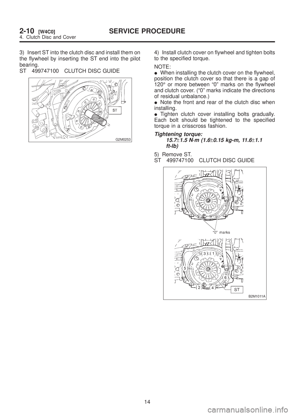
3) Insert ST into the clutch disc and install them on
the flywheel by inserting the ST end into the pilot
bearing.
ST 499747100 CLUTCH DISC GUIDE
G2M0253
4) Install clutch cover on flywheel and tighten bolts
to the specified torque.
NOTE:
IWhen installing the clutch cover on the flywheel,
position the clutch cover so that there is a gap of
120É or more between ª0º marks on the flywheel
and clutch cover. (ª0º marks indicate the directions
of residual unbalance.)
INote the front and rear of the clutch disc when
installing.
ITighten clutch cover installing bolts gradually.
Each bolt should be tightened to the specified
torque in a crisscross fashion.
Tightening torque:
15.7
±1.5 N´m (1.6±0.15 kg-m, 11.6±1.1
ft-lb)
5) Remove ST.
ST 499747100 CLUTCH DISC GUIDE
B2M1011A
14
2-10[W4C0]SERVICE PROCEDURE
4. Clutch Disc and Cover
Page 703 of 1456

2. Rear Differential
Symptom Possible cause Remedy
1. Oil leakage(1) Worn, scratched, or incorrectly seated front or
side oil seal. Scored, battered, or excessively worn
sliding surface of companion flange.Repair or replace.
(2) Clogged or damaged air breather. Clean, repair or replace.
(3) Loose bolts on differential spindle or side
retainer, or incorrectly fitted O-ring.Tighten bolts to specified torque.
Replace O-ring.
(4) Loose rear cover attaching bolts or damaged
gasket.Tighten bolts to specified torque.
Replace gasket and apply liquid
packing.
(5) Loose oil filler or drain plug. Retighten and apply liquid packing.
(6) Wear, damage or incorrectly fitting for spindle,
side retainer and oil seal.Repair or replace.
2. Seizure
NOTE:
Seized or damaged parts should
be replaced, and also other parts
should be thoroughly checked for
any defect and should be repaired
or replaced as required.(1) Insufficient backlash for hypoid gear. Readjust or replace.
(2) Excessive preload for side, rear, or front bearing. Readjust or replace.
(3) Insufficient or improper oil used. Replace seized part and fill with
specified oil to specified level.
3. Damage
NOTE:
Damaged parts should be
replaced, and also other parts
should be thoroughly checked for
any defect and should be repaired
or replaced as required.(1) Improper backlash for hypoid gear. Replace.
(2) Insufficient or excessive preload for side, rear, or
front bearing.Readjust or replace.
(3) Excessive backlash for differential gear. Replace gear or thrust washer.
(4) Loose bolts and nuts such as crown gear bolt. Retighten.
(5) Damage due to overloading. Replace.
4. Noises when starting or shift-
ing gears
NOTE:
Noises may be caused by differen-
tial assembly, universal joint, wheel
bearing, etc. Find out what is actu-
ally making noise before disassem-
bly.(1) Excessive backlash for hypoid gear. Readjust.
(2) Excessive backlash for differential gear. Replace gear or thrust washer.
(3) Insufficient preload for front or rear bearing. Readjust.
(4) Loose drive pinion nut. Tighten to specified torque.
(5) Loose bolts and nuts such as side bearing
retainer attaching bolt.Tighten to specified torque.
5. Noises when cornering(1) Damaged differential gear. Replace.
(2) Excessive wear or damage of thrust washer. Replace.
(3) Broken pinion mate shaft. Replace.
(4) Seized or damaged side bearing. Replace.
6. Gear noises
NOTE:
Since noises from engine, muffler,
transmission, propeller shaft, wheel
bearings, tires, and body are
sometimes mistaken for noises
from differential assembly, be care-
ful in checking them. Inspection
methods to locate noises include
coasting, accelerating, cruising,
and jacking-up all four wheels.
Perform these inspections accord-
ing to condition of trouble. When
listening to noises, shift gears into
four wheel drive and fourth speed
position, trying to pick up only dif-
ferential noise.(1) Improper tooth contact of hypoid gear. Readjust or replace hypoid gear
set.
(2) Improper backlash for hypoid gear. Readjust.
(3) Scored or chipped teeth of hypoid gear. Replace hypoid gear set.
(4) Seized hypoid gear. Replace hypoid gear set.
(5) Improper preload for front or rear bearings. Readjust.
(6) Seized, scored, or chipped front or rear bearing. Replace.
(7) Seized, scored, or chipped side bearing. Replace.
(8) Vibrating differential carrier. Replace.
52
3-4[K200]DIAGNOSTICS
2. Rear Differential
Page 711 of 1456

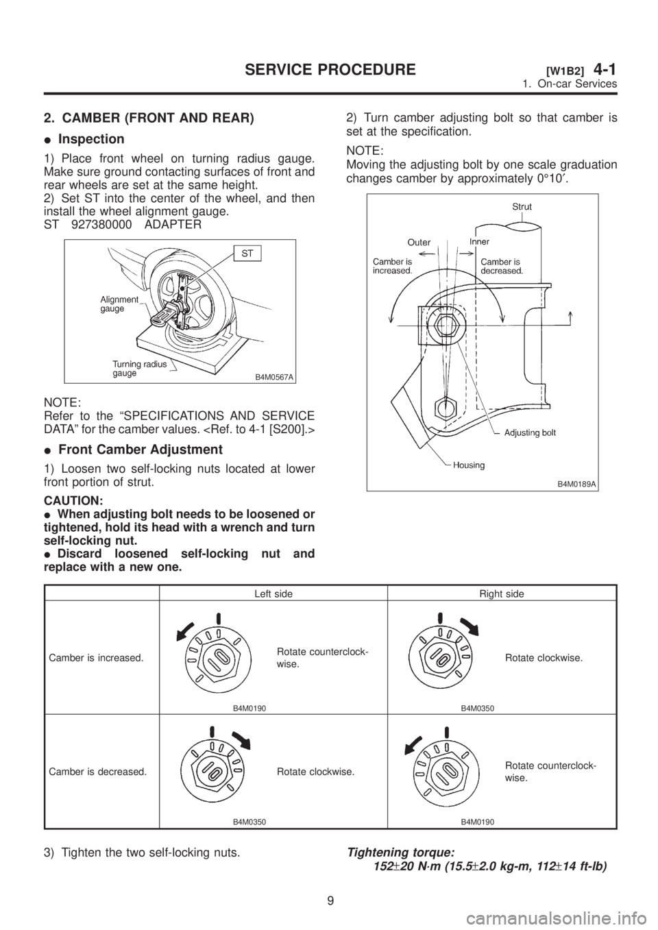
2. CAMBER (FRONT AND REAR)
IInspection
1) Place front wheel on turning radius gauge.
Make sure ground contacting surfaces of front and
rear wheels are set at the same height.
2) Set ST into the center of the wheel, and then
install the wheel alignment gauge.
ST 927380000 ADAPTER
B4M0567A
NOTE:
Refer to the ªSPECIFICATIONS AND SERVICE
DATAº for the camber values.
IFront Camber Adjustment
1) Loosen two self-locking nuts located at lower
front portion of strut.
CAUTION:
IWhen adjusting bolt needs to be loosened or
tightened, hold its head with a wrench and turn
self-locking nut.
IDiscard loosened self-locking nut and
replace with a new one.2) Turn camber adjusting bolt so that camber is
set at the specification.
NOTE:
Moving the adjusting bolt by one scale graduation
changes camber by approximately 0É10¢.
B4M0189A
Left side Right side
Camber is increased.
B4M0190
Rotate counterclock-
wise.
B4M0350
Rotate clockwise.
Camber is decreased.
B4M0350
Rotate clockwise.
B4M0190
Rotate counterclock-
wise.
3) Tighten the two self-locking nuts.Tightening torque:
152
±20 N´m (15.5±2.0 kg-m, 112±14 ft-lb)
9
[W1B2]4-1SERVICE PROCEDURE
1. On-car Services
Page 713 of 1456

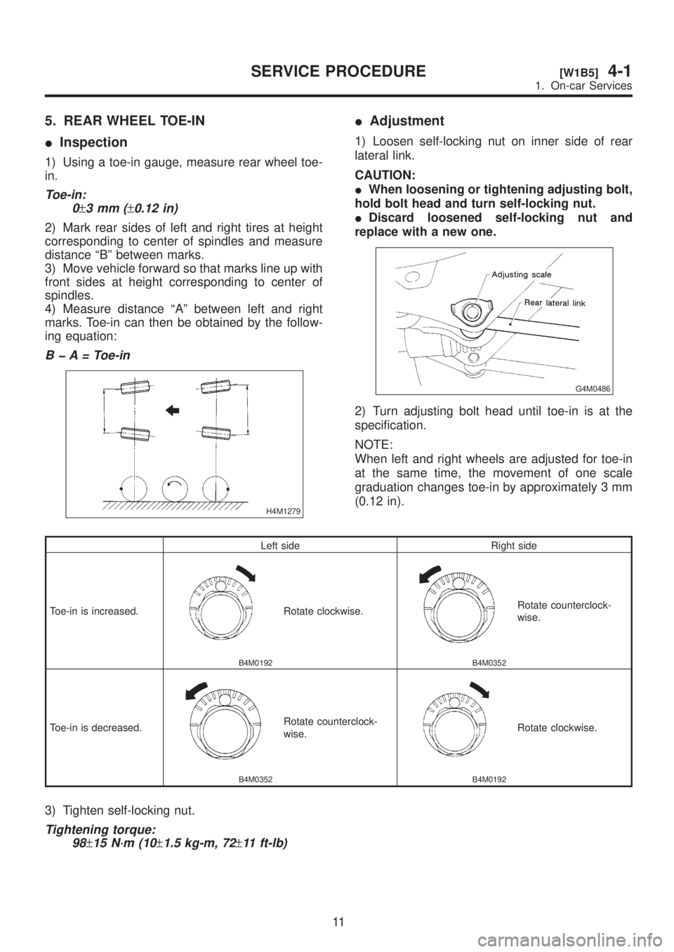
5. REAR WHEEL TOE-IN
IInspection
1) Using a toe-in gauge, measure rear wheel toe-
in.
Toe-in:
0
±3mm(±0.12 in)
2) Mark rear sides of left and right tires at height
corresponding to center of spindles and measure
distance ªBº between marks.
3) Move vehicle forward so that marks line up with
front sides at height corresponding to center of
spindles.
4) Measure distance ªAº between left and right
marks. Toe-in can then be obtained by the follow-
ing equation:
B þ A = Toe-in
H4M1279
IAdjustment
1) Loosen self-locking nut on inner side of rear
lateral link.
CAUTION:
IWhen loosening or tightening adjusting bolt,
hold bolt head and turn self-locking nut.
IDiscard loosened self-locking nut and
replace with a new one.
G4M0486
2) Turn adjusting bolt head until toe-in is at the
specification.
NOTE:
When left and right wheels are adjusted for toe-in
at the same time, the movement of one scale
graduation changes toe-in by approximately 3 mm
(0.12 in).
Left side Right side
Toe-in is increased.
B4M0192
Rotate clockwise.
B4M0352
Rotate counterclock-
wise.
Toe-in is decreased.
B4M0352
Rotate counterclock-
wise.
B4M0192
Rotate clockwise.
3) Tighten self-locking nut.
Tightening torque:
98
±15 N´m (10±1.5 kg-m, 72±11 ft-lb)
11
[W1B5]4-1SERVICE PROCEDURE
1. On-car Services
Page 718 of 1456

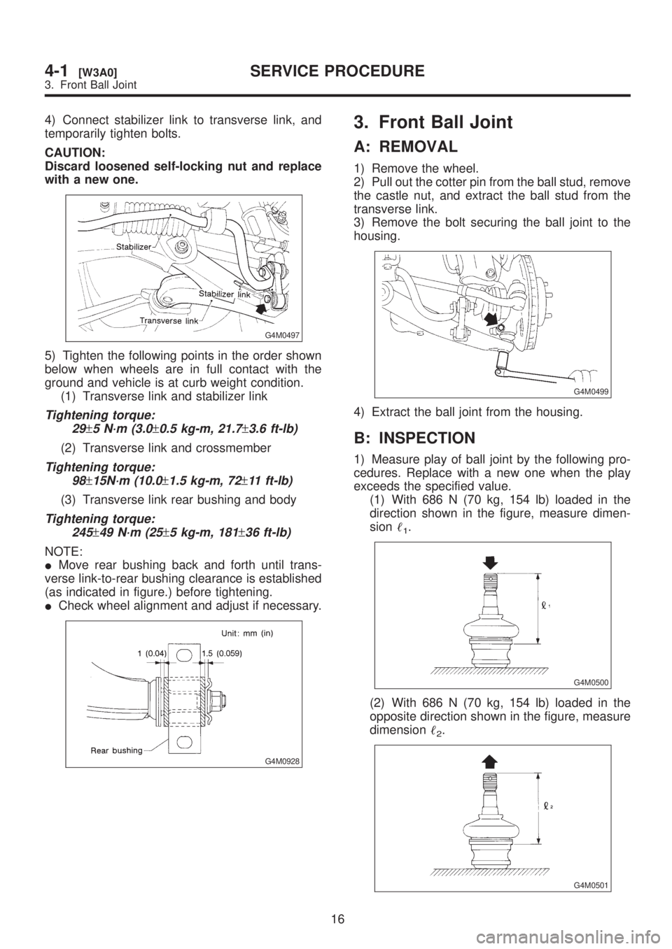
4) Connect stabilizer link to transverse link, and
temporarily tighten bolts.
CAUTION:
Discard loosened self-locking nut and replace
with a new one.
G4M0497
5) Tighten the following points in the order shown
below when wheels are in full contact with the
ground and vehicle is at curb weight condition.
(1) Transverse link and stabilizer link
Tightening torque:
29
±5 N´m (3.0±0.5 kg-m, 21.7±3.6 ft-lb)
(2) Transverse link and crossmember
Tightening torque:
98
±15N´m (10.0±1.5 kg-m, 72±11 ft-lb)
(3) Transverse link rear bushing and body
Tightening torque:
245
±49 N´m (25±5 kg-m, 181±36 ft-lb)
NOTE:
IMove rear bushing back and forth until trans-
verse link-to-rear bushing clearance is established
(as indicated in figure.) before tightening.
ICheck wheel alignment and adjust if necessary.
G4M0928
3. Front Ball Joint
A: REMOVAL
1) Remove the wheel.
2) Pull out the cotter pin from the ball stud, remove
the castle nut, and extract the ball stud from the
transverse link.
3) Remove the bolt securing the ball joint to the
housing.
G4M0499
4) Extract the ball joint from the housing.
B: INSPECTION
1) Measure play of ball joint by the following pro-
cedures. Replace with a new one when the play
exceeds the specified value.
(1) With 686 N (70 kg, 154 lb) loaded in the
direction shown in the figure, measure dimen-
sion
1.
G4M0500
(2) With 686 N (70 kg, 154 lb) loaded in the
opposite direction shown in the figure, measure
dimension
2.
G4M0501
16
4-1[W3A0]SERVICE PROCEDURE
3. Front Ball Joint