1999 SUBARU LEGACY fuse box
[x] Cancel search: fuse boxPage 352 of 1456
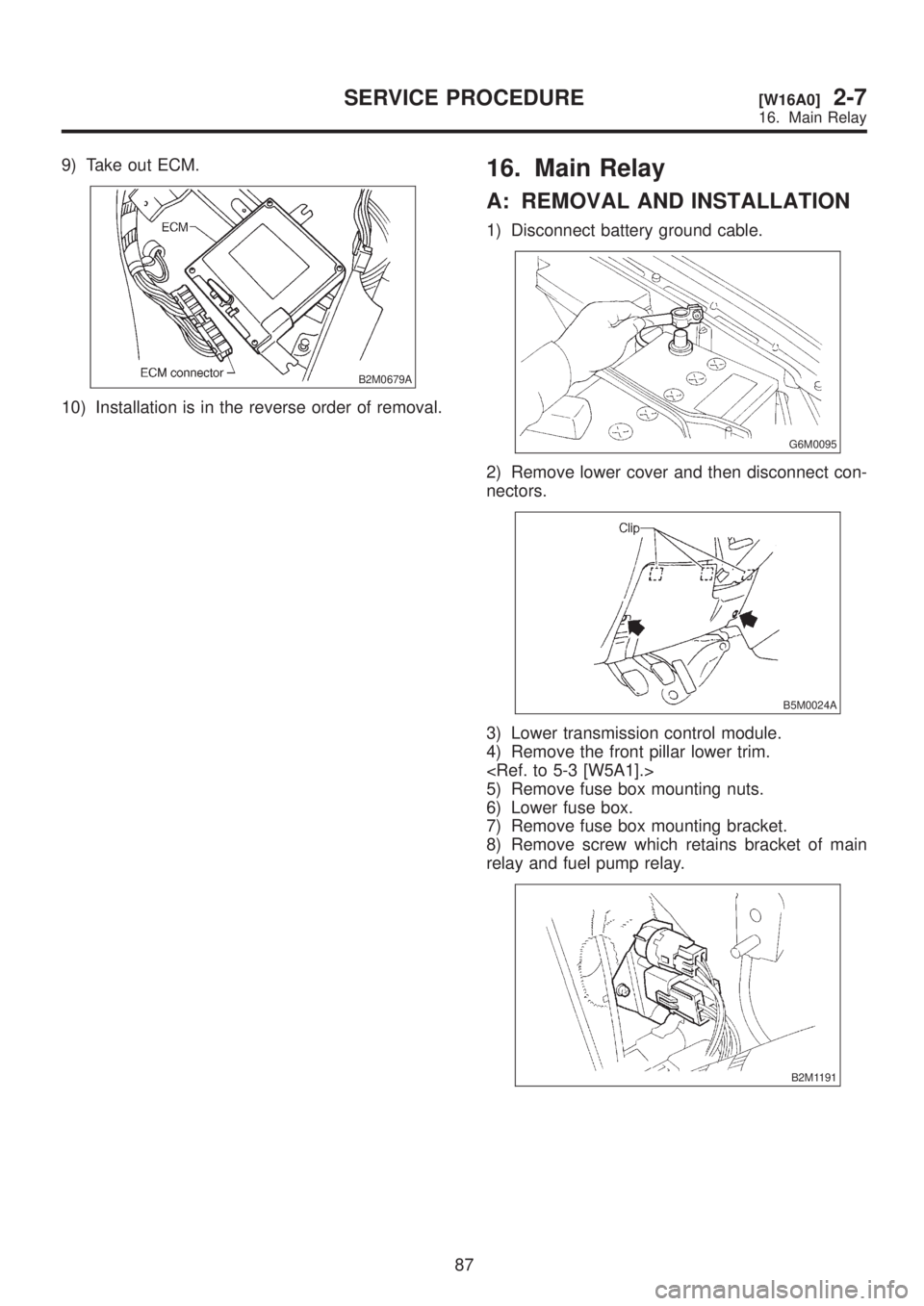
9) Take out ECM.
B2M0679A
10) Installation is in the reverse order of removal.
16. Main Relay
A: REMOVAL AND INSTALLATION
1) Disconnect battery ground cable.
G6M0095
2) Remove lower cover and then disconnect con-
nectors.
B5M0024A
3) Lower transmission control module.
4) Remove the front pillar lower trim.
5) Remove fuse box mounting nuts.
6) Lower fuse box.
7) Remove fuse box mounting bracket.
8) Remove screw which retains bracket of main
relay and fuel pump relay.
B2M1191
87
[W16A0]2-7SERVICE PROCEDURE
16. Main Relay
Page 353 of 1456
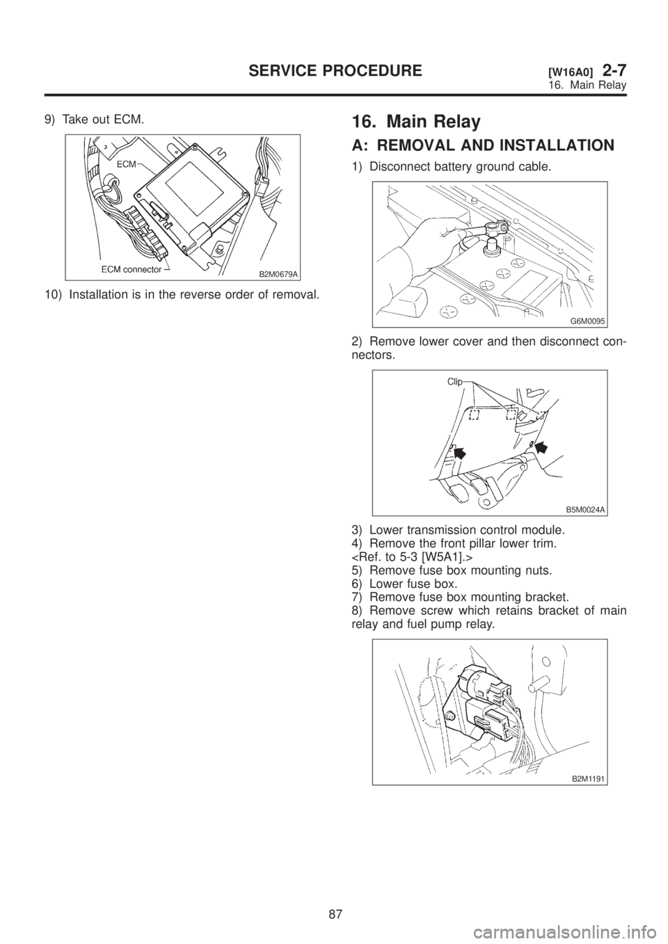
9) Take out ECM.
B2M0679A
10) Installation is in the reverse order of removal.
16. Main Relay
A: REMOVAL AND INSTALLATION
1) Disconnect battery ground cable.
G6M0095
2) Remove lower cover and then disconnect con-
nectors.
B5M0024A
3) Lower transmission control module.
4) Remove the front pillar lower trim.
5) Remove fuse box mounting nuts.
6) Lower fuse box.
7) Remove fuse box mounting bracket.
8) Remove screw which retains bracket of main
relay and fuel pump relay.
B2M1191
87
[W16A0]2-7SERVICE PROCEDURE
16. Main Relay
Page 354 of 1456
17. Fuel Pump Relay
A: REMOVAL AND INSTALLATION
1) Disconnect battery ground cable.
G6M0095
2) Remove lower cover and then disconnect con-
nectors.
B5M0024A
3) Lower transmission control module.
4) Remove the front pillar lower trim.
5) Remove fuse box mounting nuts.
6) Lower fuse box.
7) Remove fuse box mounting bracket.
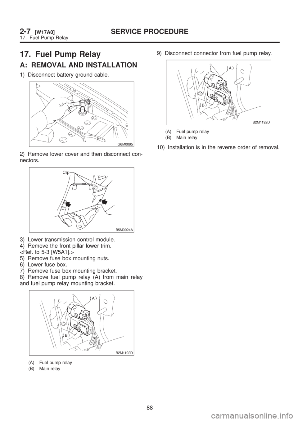
8) Remove fuel pump relay (A) from main relay
and fuel pump relay mounting bracket.
B2M1192D
(A) Fuel pump relay
(B) Main relay
9) Disconnect connector from fuel pump relay.
B2M1192D
(A) Fuel pump relay
(B) Main relay
10) Installation is in the reverse order of removal.
88
2-7[W17A0]SERVICE PROCEDURE
17. Fuel Pump Relay
Page 1226 of 1456
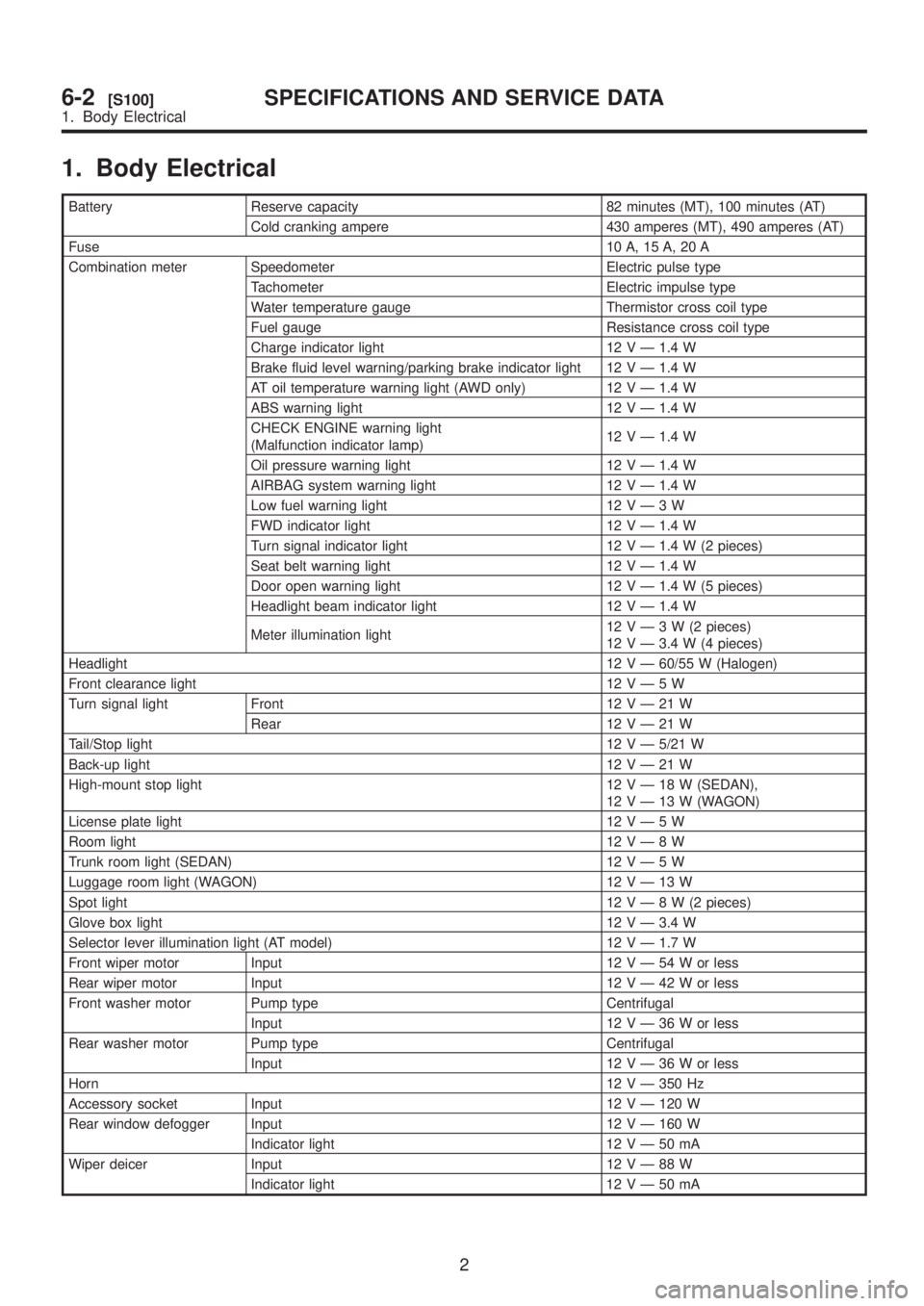
1. Body Electrical
Battery Reserve capacity 82 minutes (MT), 100 minutes (AT)
Cold cranking ampere 430 amperes (MT), 490 amperes (AT)
Fuse10 A, 15 A, 20 A
Combination meter Speedometer Electric pulse type
Tachometer Electric impulse type
Water temperature gauge Thermistor cross coil type
Fuel gauge Resistance cross coil type
Charge indicator light 12 V Ð 1.4 W
Brake fluid level warning/parking brake indicator light 12 V Ð 1.4 W
AT oil temperature warning light (AWD only) 12 V Ð 1.4 W
ABS warning light 12 V Ð 1.4 W
CHECK ENGINE warning light
(Malfunction indicator lamp)12 V Ð 1.4 W
Oil pressure warning light 12 V Ð 1.4 W
AIRBAG system warning light 12 V Ð 1.4 W
Low fuel warning light 12VÐ3W
FWD indicator light 12 V Ð 1.4 W
Turn signal indicator light 12 V Ð 1.4 W (2 pieces)
Seat belt warning light 12 V Ð 1.4 W
Door open warning light 12 V Ð 1.4 W (5 pieces)
Headlight beam indicator light 12 V Ð 1.4 W
Meter illumination light12VÐ3W(2pieces)
12 V Ð 3.4 W (4 pieces)
Headlight12 V Ð 60/55 W (Halogen)
Front clearance light 12VÐ5W
Turn signal light Front 12VÐ21W
Rear 12VÐ21W
Tail/Stop light12 V Ð 5/21 W
Back-up light12VÐ21W
High-mount stop light 12VÐ18W(SEDAN),
12VÐ13W(WAGON)
License plate light 12VÐ5W
Room light12VÐ8W
Trunk room light (SEDAN) 12VÐ5W
Luggage room light (WAGON) 12VÐ13W
Spot light12VÐ8W(2pieces)
Glove box light 12 V Ð 3.4 W
Selector lever illumination light (AT model) 12 V Ð 1.7 W
Front wiper motor Input 12VÐ54Worless
Rear wiper motor Input 12VÐ42Worless
Front washer motor Pump type Centrifugal
Input 12VÐ36Worless
Rear washer motor Pump type Centrifugal
Input 12VÐ36Worless
Horn12 V Ð 350 Hz
Accessory socket Input 12 V Ð 120 W
Rear window defogger Input 12 V Ð 160 W
Indicator light 12VÐ50mA
Wiper deicer Input 12VÐ88W
Indicator light 12VÐ50mA
2
6-2[S100]SPECIFICATIONS AND SERVICE DATA
1. Body Electrical
Page 1290 of 1456
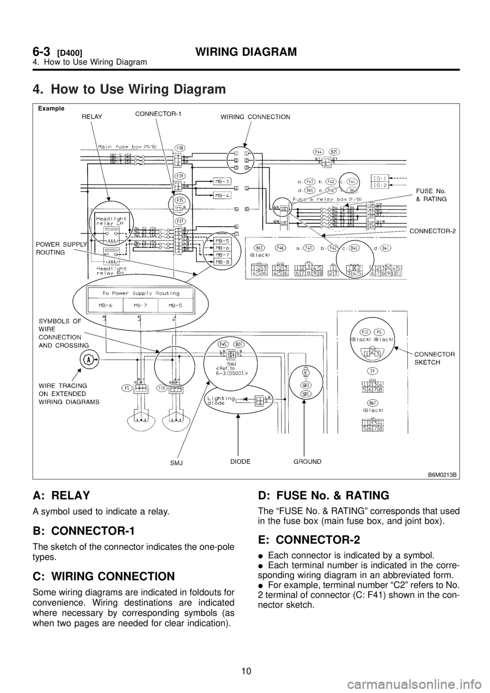
4. How to Use Wiring Diagram
B6M0213B
A: RELAY
A symbol used to indicate a relay.
B: CONNECTOR-1
The sketch of the connector indicates the one-pole
types.
C: WIRING CONNECTION
Some wiring diagrams are indicated in foldouts for
convenience. Wiring destinations are indicated
where necessary by corresponding symbols (as
when two pages are needed for clear indication).
D: FUSE No. & RATING
The ªFUSE No. & RATINGº corresponds that used
in the fuse box (main fuse box, and joint box).
E: CONNECTOR-2
IEach connector is indicated by a symbol.
IEach terminal number is indicated in the corre-
sponding wiring diagram in an abbreviated form.
IFor example, terminal number ªC2º refers to No.
2 terminal of connector (C: F41) shown in the con-
nector sketch.
10
6-3[D400]WIRING DIAGRAM
4. How to Use Wiring Diagram
Page 1291 of 1456
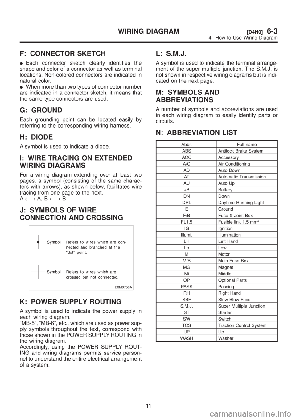
F: CONNECTOR SKETCH
IEach connector sketch clearly identifies the
shape and color of a connector as well as terminal
locations. Non-colored connectors are indicated in
natural color.
IWhen more than two types of connector number
are indicated in a connector sketch, it means that
the same type connectors are used.
G: GROUND
Each grounding point can be located easily by
referring to the corresponding wiring harness.
H: DIODE
A symbol is used to indicate a diode.
I: WIRE TRACING ON EXTENDED
WIRING DIAGRAMS
For a wiring diagram extending over at least two
pages, a symbol (consisting of the same charac-
ters with arrows), as shown below, facilitates wire
tracing from one page to the next.
A¨A, B¨B
J: SYMBOLS OF WIRE
CONNECTION AND CROSSING
B6M0750A
K: POWER SUPPLY ROUTING
A symbol is used to indicate the power supply in
each wiring diagram.
ªMB-5º, ªMB-6º, etc., which are used as power sup-
ply symbols throughout the text, correspond with
those shown in the POWER SUPPLY ROUTING in
the wiring diagram.
Accordingly, using the POWER SUPPLY ROUT-
ING and wiring diagrams permits service person-
nel to understand the entire electrical arrangement
of a system.
L: S.M.J.
A symbol is used to indicate the terminal arrange-
ment of the super multiple junction. The S.M.J. is
not shown in respective wiring diagrams but is indi-
cated on the next page.
M: SYMBOLS AND
ABBREVIATIONS
A number of symbols and abbreviations are used
in each wiring diagram to easily identify parts or
circuits.
N: ABBREVIATION LIST
Abbr. Full name
ABS Antilock Brake System
ACC Accessory
A/C Air Conditioning
AD Auto Down
AT Automatic Transmission
AU Auto Up
+B Battery
DN Down
DRL Daytime Running Light
E Ground
F/B Fuse & Joint Box
FL1.5 Fusible link 1.5 mm
2
IG Ignition
Illumi. Illumination
LH Left Hand
Lo Low
M Motor
M/B Main Fuse Box
MG Magnet
Mi Middle
OP Optional Parts
PASS Passing
RH Right Hand
SBF Slow Blow Fuse
S.M.J. Super Multiple Junction
ST Starter
SW Switch
TCS Traction Control System
UP Up
WASH Washer
11
[D4N0]6-3WIRING DIAGRAM
4. How to Use Wiring Diagram
Page 1296 of 1456
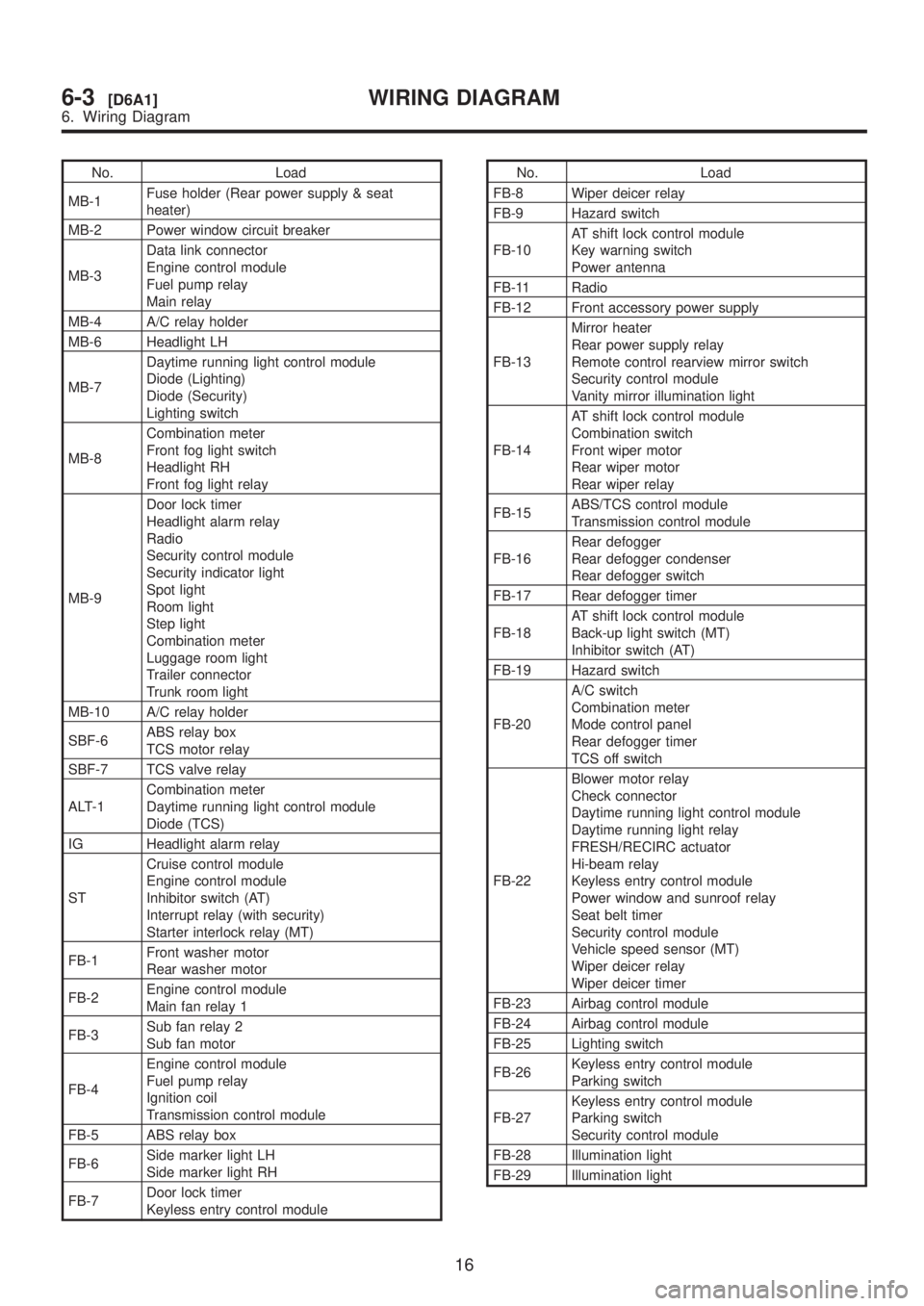
No. Load
MB-1Fuse holder (Rear power supply & seat
heater)
MB-2 Power window circuit breaker
MB-3Data link connector
Engine control module
Fuel pump relay
Main relay
MB-4 A/C relay holder
MB-6 Headlight LH
MB-7Daytime running light control module
Diode (Lighting)
Diode (Security)
Lighting switch
MB-8Combination meter
Front fog light switch
Headlight RH
Front fog light relay
MB-9Door lock timer
Headlight alarm relay
Radio
Security control module
Security indicator light
Spot light
Room light
Step light
Combination meter
Luggage room light
Trailer connector
Trunk room light
MB-10 A/C relay holder
SBF-6ABS relay box
TCS motor relay
SBF-7 TCS valve relay
ALT-1Combination meter
Daytime running light control module
Diode (TCS)
IG Headlight alarm relay
STCruise control module
Engine control module
Inhibitor switch (AT)
Interrupt relay (with security)
Starter interlock relay (MT)
FB-1Front washer motor
Rear washer motor
FB-2Engine control module
Main fan relay 1
FB-3Sub fan relay 2
Sub fan motor
FB-4Engine control module
Fuel pump relay
Ignition coil
Transmission control module
FB-5 ABS relay box
FB-6Side marker light LH
Side marker light RH
FB-7Door lock timer
Keyless entry control moduleNo. Load
FB-8 Wiper deicer relay
FB-9 Hazard switch
FB-10AT shift lock control module
Key warning switch
Power antenna
FB-11 Radio
FB-12 Front accessory power supply
FB-13Mirror heater
Rear power supply relay
Remote control rearview mirror switch
Security control module
Vanity mirror illumination light
FB-14AT shift lock control module
Combination switch
Front wiper motor
Rear wiper motor
Rear wiper relay
FB-15ABS/TCS control module
Transmission control module
FB-16Rear defogger
Rear defogger condenser
Rear defogger switch
FB-17 Rear defogger timer
FB-18AT shift lock control module
Back-up light switch (MT)
Inhibitor switch (AT)
FB-19 Hazard switch
FB-20A/C switch
Combination meter
Mode control panel
Rear defogger timer
TCS off switch
FB-22Blower motor relay
Check connector
Daytime running light control module
Daytime running light relay
FRESH/RECIRC actuator
Hi-beam relay
Keyless entry control module
Power window and sunroof relay
Seat belt timer
Security control module
Vehicle speed sensor (MT)
Wiper deicer relay
Wiper deicer timer
FB-23 Airbag control module
FB-24 Airbag control module
FB-25 Lighting switch
FB-26Keyless entry control module
Parking switch
FB-27Keyless entry control module
Parking switch
Security control module
FB-28 Illumination light
FB-29 Illumination light
16
6-3[D6A1]WIRING DIAGRAM
6. Wiring Diagram