Page 35 of 1456

3. Engine Idle Speed
A: MEASUREMENT
1) Before checking idle speed, check the follow-
ing:
(1) Ensure that air cleaner element is free from
clogging, ignition timing is correct, spark plugs
are in good condition, and that hoses are con-
nected properly.
(2) Ensure that malfunction indicator light
(CHECK ENGINE light) does not illuminate.
2) Warm-up the engine.
3) Stop the engine, and turn ignition switch to
OFF.
4) When using SUBARU SELECT MONITOR;
NOTE:
For detailed operation procedures, refer to the
SUBARU SELECT MONITOR OPERATION
MANUAL.
(1) Insert the cartridge to SUBARU SELECT
MONITOR.
ST 24082AA090 CARTRIDGE
S2M0286A
(2) Connect SUBARU SELECT MONITOR to
the data link connector.
(3) Turn ignition switch to ON, and SUBARU
SELECT MONITOR switch to ON.
(4) Select {2. Each System Check} in Main
Menu.
(5) Select {EGI/EMPI} in Selection Menu.
(6) Select {1. Current Data Display & Save} in
EGI/EMPI Diagnosis.
(7) Select {1.12 Data Display} in Data Display
Menu.(8) Start the engine, and read engine idle
speed.
S2M0098
5) When using tachometer (Secondary pick-up
type).
(1) Attach the pick-up clip to No. 1 cylinder
spark plug cord.
(2) Start the engine, and read engine idle
speed.
B2M2011
NOTE:
IWhen using the OBD-II general scan tool, care-
fully read its operation manual.
IThis ignition system provides simultaneous igni-
tion for #1 and #2 plugs. It must be noted that
some tachometers may register twice that of actual
engine speed.
6) Check idle speed when unloaded. (With
headlights, heater fan, rear defroster, radiator fan,
air conditioning, etc. OFF)
Idle speed (No load and gears in neutral (MT),
or N or P (AT) position):
700
±100 rpm
7) Check idle speed when loaded. (Turn air con-
ditioning switch to |P¢rdquo;ON|P'ldquo; and oper-
ate compressor for at least one minute before
measurement.)
Idle speed [A/C ªONº, no load and gears in
neutral (MT) or N or P (AT) position]:
850
±50 rpm
3
[W3A0]2-2SERVICE PROCEDURE
3. Engine Idle Speed
Page 160 of 1456
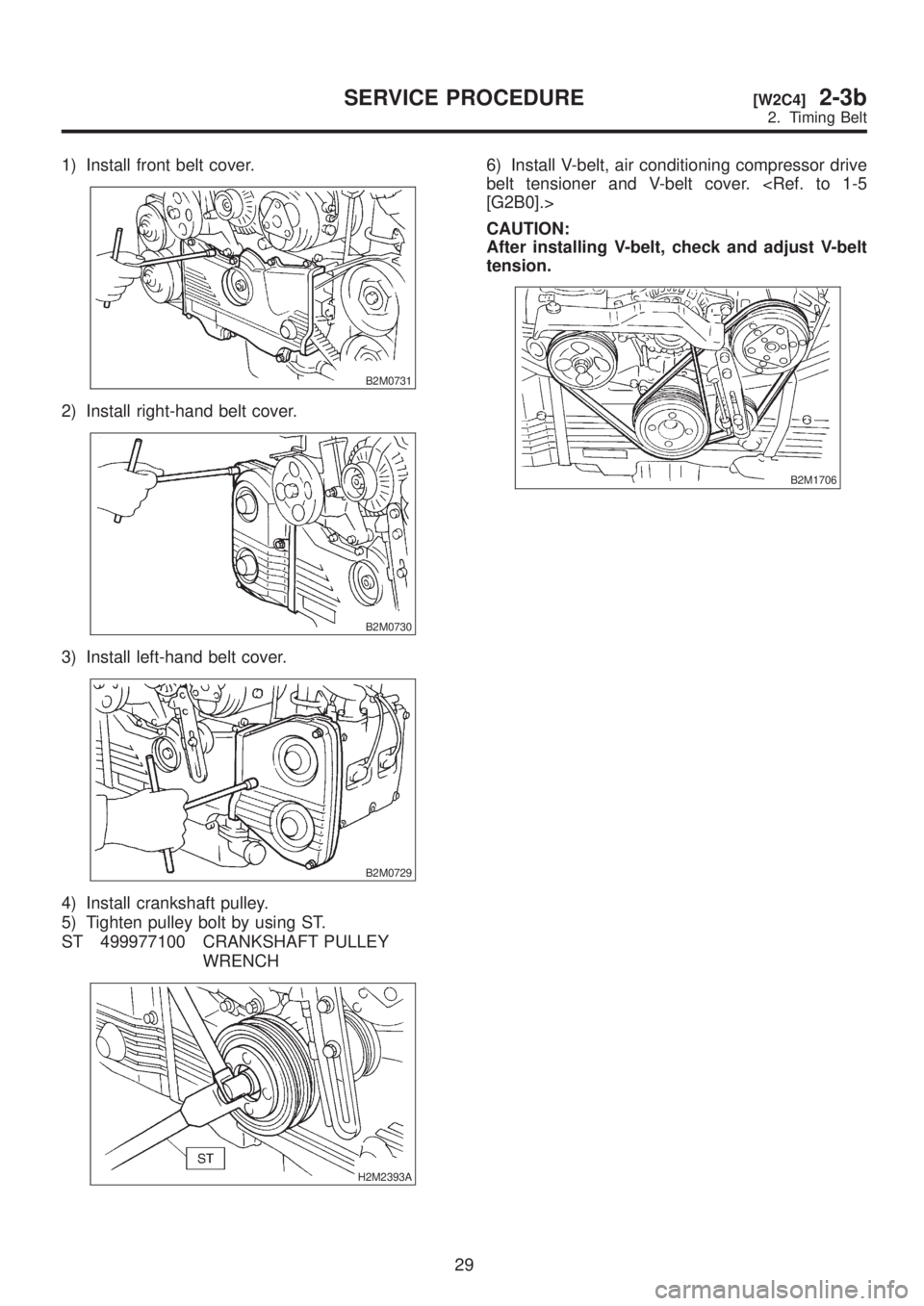
1) Install front belt cover.
B2M0731
2) Install right-hand belt cover.
B2M0730
3) Install left-hand belt cover.
B2M0729
4) Install crankshaft pulley.
5) Tighten pulley bolt by using ST.
ST 499977100 CRANKSHAFT PULLEY
WRENCH
H2M2393A
6) Install V-belt, air conditioning compressor drive
belt tensioner and V-belt cover.
[G2B0].>
CAUTION:
After installing V-belt, check and adjust V-belt
tension.
B2M1706
29
[W2C4]2-3bSERVICE PROCEDURE
2. Timing Belt
Page 976 of 1456
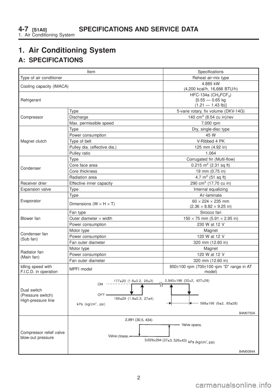
1. Air Conditioning System
A: SPECIFICATIONS
Item Specifications
Type of air conditioner Reheat air-mix type
Cooling capacity (IMACA)4.885 kW
(4,200 kcal/h, 16,666 BTU/h)
RefrigerantHFC-134a (CH
2FCF3)
[0.55 Ð 0.65 kg
(1.21 Ð 1.43 lb)]
CompressorType 5-vane rotary, fix volume (DKV-14G)
Discharge 140 cm
3(8.54 cu in)/rev
Max. permissible speed 7,000 rpm
Magnet clutchType Dry, single-disc type
Power consumption 45 W
Type of belt V-Ribbed 4 PK
Pulley dia. (effective dia.) 125 mm (4.92 in)
Pulley ratio 1.064
CondenserType Corrugated fin (Multi-flow)
Core face area 0.215 m
2(2.31 sq ft)
Core thickness 19 mm (0.75 in)
Radiation area 4.7 m
2(51 sq ft)
Receiver drier Effective inner capacity 290 cm3(17.70 cu in)
Expansion valve Type Internal equalizing
EvaporatorType A-laminate
Dimensions (W´H´T)60´224´235 mm
(2.36´8.82´9.25 in)
Blower fanFan type Sirocco fan
Outer diameter´width 150´75 mm (5.91´2.95 in)
Power consumption 230 W at 12 V
Condenser fan
(Sub fan)Motor type Magnet
Power consumption 120 W at 12 V
Fan outer diameter 320 mm (12.60 in)
Radiator fan
(Main fan)Motor type Magnet
Power consumption 120 W at 12 V
Fan outer diameter 320 mm (12.60 in)
Idling speed with
F.I.C.D. in operationMPFI model850±100 rpm (700±100 rpm ªDº range in AT
model)
Dual switch
(Pressure switch)
High-pressure line
B4M0755A
Compressor relief valve
blow-out pressure
B4M0084A
2
4-7[S1A0]SPECIFICATIONS AND SERVICE DATA
1. Air Conditioning System
Page 977 of 1456
Item Specifications
Thermo control amplifier
working temperature
(Evaporator outlet air)
B4M0756B
3
[S1A0]4-7SPECIFICATIONS AND SERVICE DATA
1. Air Conditioning System
Page 978 of 1456
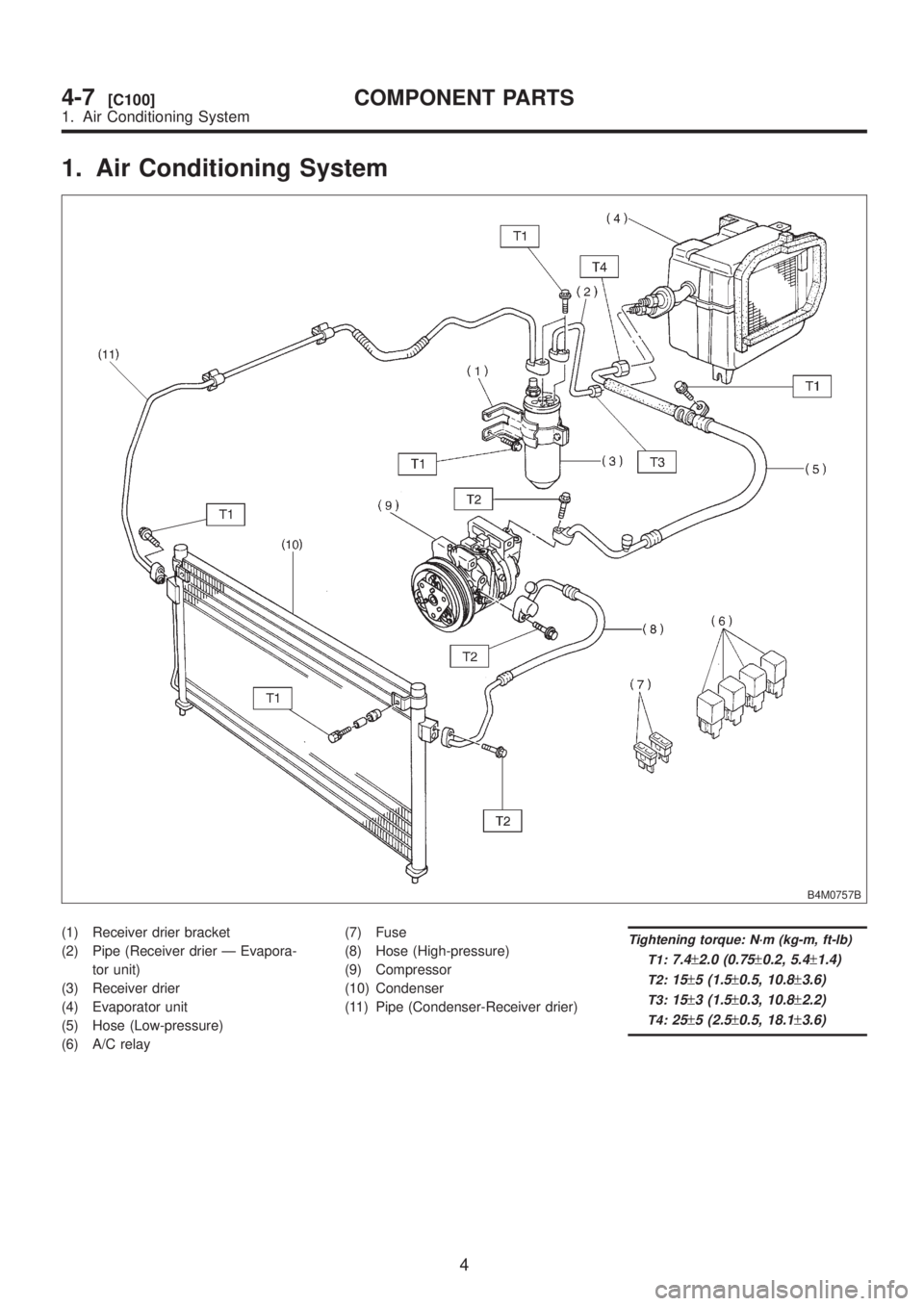
1. Air Conditioning System
B4M0757B
(1) Receiver drier bracket
(2) Pipe (Receiver drier Ð Evapora-
tor unit)
(3) Receiver drier
(4) Evaporator unit
(5) Hose (Low-pressure)
(6) A/C relay(7) Fuse
(8) Hose (High-pressure)
(9) Compressor
(10) Condenser
(11) Pipe (Condenser-Receiver drier)Tightening torque: N´m (kg-m, ft-lb)
T1:
7.4±2.0 (0.75±0.2, 5.4±1.4)
T2:15±5 (1.5±0.5, 10.8±3.6)
T3:15±3 (1.5±0.3, 10.8±2.2)
T4:25±5 (2.5±0.5, 18.1±3.6)
4
4-7[C100]COMPONENT PARTS
1. Air Conditioning System
Page 981 of 1456

1. Safety Precautions
A: HFC-134a AIR CONDITIONING
SYSTEM
Component parts of the cooling system,
refrigerant, compressor oil, and other parts are not
the same for the HFC- 134a system and the older
CFC-12 system. Do not interchange parts or liquid.
Vehicles with HFC-134a air conditioning systems,
use only HFC-134a parts that are indicated on a
label attached to the vehicle. Before performing
any maintenance, verify the type of air conditioning
system installed in the vehicle.
B4M0780
B: COMPRESSOR OIL
Do not use any compressor oil that is not specifi-
cally designated for the HFC-134a air conditioning
system; only use ZXL200PG. Also, do not use
HFC-134a compressor oil in the CFC-12 air condi-
tioning system. If compression oils are mixed, poor
lubrication will result and the compressor itself may
be damaged.
Because HFC-134a compressor oil is very hygro-
scopic (easily absorbs moisture), when parts of the
air conditioning system are being removed, quickly
install a blind plug to prevent contact with the out-
side air. Also, always make sure that the service
container for compressor oil is tightly closed except
when in use. Store compressor oil in a tightly
closed steel container.
C: REFRIGERANT
Do not put CFC-12 refrigerant into a HFC-134a air
conditioning system. Also, do not put HFC-134a
refrigerant into a CFC-12 air conditioning system.
If the wrong refrigerant is used, poor lubrication willresult and the compressor itself may be destroyed.
7
[W1C0]4-7SERVICE PROCEDURE
1. Safety Precautions
Page 1014 of 1456
1. Air Conditioning System
Diagnosis
B4M1099A
34
4-7[K100]DIAGNOSTICS
1. Air Conditioning System Diagnosis
Page 1015 of 1456
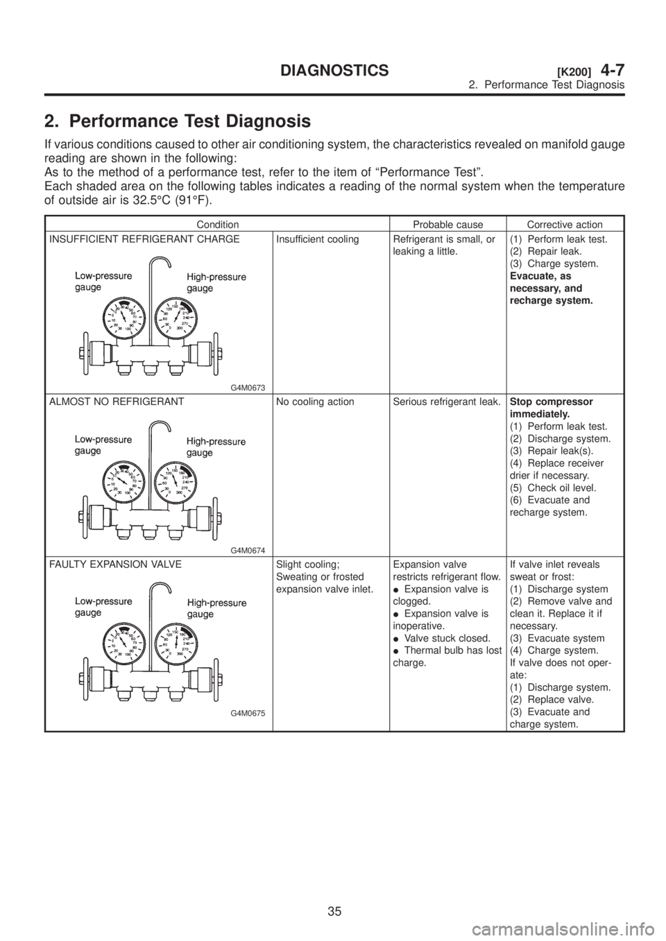
2. Performance Test Diagnosis
If various conditions caused to other air conditioning system, the characteristics revealed on manifold gauge
reading are shown in the following:
As to the method of a performance test, refer to the item of ªPerformance Testº.
Each shaded area on the following tables indicates a reading of the normal system when the temperature
of outside air is 32.5ÉC (91ÉF).
Condition Probable cause Corrective action
INSUFFICIENT REFRIGERANT CHARGE
G4M0673
Insufficient cooling Refrigerant is small, or
leaking a little.(1) Perform leak test.
(2) Repair leak.
(3) Charge system.
Evacuate, as
necessary, and
recharge system.
ALMOST NO REFRIGERANT
G4M0674
No cooling action Serious refrigerant leak.Stop compressor
immediately.
(1) Perform leak test.
(2) Discharge system.
(3) Repair leak(s).
(4) Replace receiver
drier if necessary.
(5) Check oil level.
(6) Evacuate and
recharge system.
FAULTY EXPANSION VALVE
G4M0675
Slight cooling;
Sweating or frosted
expansion valve inlet.Expansion valve
restricts refrigerant flow.
IExpansion valve is
clogged.
IExpansion valve is
inoperative.
IValve stuck closed.
IThermal bulb has lost
charge.If valve inlet reveals
sweat or frost:
(1) Discharge system
(2) Remove valve and
clean it. Replace it if
necessary.
(3) Evacuate system
(4) Charge system.
If valve does not oper-
ate:
(1) Discharge system.
(2) Replace valve.
(3) Evacuate and
charge system.
35
[K200]4-7DIAGNOSTICS
2. Performance Test Diagnosis
![SUBARU LEGACY 1999 Service Repair Manual Item Specifications
Thermo control amplifier
working temperature
(Evaporator outlet air)
B4M0756B
3
[S1A0]4-7SPECIFICATIONS AND SERVICE DATA
1. Air Conditioning System](/manual-img/17/57435/w960_57435-976.png "SUBARU LEGACY 1999 Service Repair Manual Item Specifications
Thermo control amplifier
working temperature
(Evaporator outlet air)
B4M0756B
3
[S1A0]4-7SPECIFICATIONS AND SERVICE DATA
1. Air Conditioning System")
![SUBARU LEGACY 1999 Service Repair Manual 1. Air Conditioning System
Diagnosis
B4M1099A
34
4-7[K100]DIAGNOSTICS
1. Air Conditioning System Diagnosis](/manual-img/17/57435/w960_57435-1013.png "SUBARU LEGACY 1999 Service Repair Manual 1. Air Conditioning System
Diagnosis
B4M1099A
34
4-7[K100]DIAGNOSTICS
1. Air Conditioning System Diagnosis")