1999 SUBARU LEGACY Tachometer
[x] Cancel search: TachometerPage 35 of 1456

3. Engine Idle Speed
A: MEASUREMENT
1) Before checking idle speed, check the follow-
ing:
(1) Ensure that air cleaner element is free from
clogging, ignition timing is correct, spark plugs
are in good condition, and that hoses are con-
nected properly.
(2) Ensure that malfunction indicator light
(CHECK ENGINE light) does not illuminate.
2) Warm-up the engine.
3) Stop the engine, and turn ignition switch to
OFF.
4) When using SUBARU SELECT MONITOR;
NOTE:
For detailed operation procedures, refer to the
SUBARU SELECT MONITOR OPERATION
MANUAL.
(1) Insert the cartridge to SUBARU SELECT
MONITOR.
ST 24082AA090 CARTRIDGE
S2M0286A
(2) Connect SUBARU SELECT MONITOR to
the data link connector.
(3) Turn ignition switch to ON, and SUBARU
SELECT MONITOR switch to ON.
(4) Select {2. Each System Check} in Main
Menu.
(5) Select {EGI/EMPI} in Selection Menu.
(6) Select {1. Current Data Display & Save} in
EGI/EMPI Diagnosis.
(7) Select {1.12 Data Display} in Data Display
Menu.(8) Start the engine, and read engine idle
speed.
S2M0098
5) When using tachometer (Secondary pick-up
type).
(1) Attach the pick-up clip to No. 1 cylinder
spark plug cord.
(2) Start the engine, and read engine idle
speed.
B2M2011
NOTE:
IWhen using the OBD-II general scan tool, care-
fully read its operation manual.
IThis ignition system provides simultaneous igni-
tion for #1 and #2 plugs. It must be noted that
some tachometers may register twice that of actual
engine speed.
6) Check idle speed when unloaded. (With
headlights, heater fan, rear defroster, radiator fan,
air conditioning, etc. OFF)
Idle speed (No load and gears in neutral (MT),
or N or P (AT) position):
700
±100 rpm
7) Check idle speed when loaded. (Turn air con-
ditioning switch to |P¢rdquo;ON|P'ldquo; and oper-
ate compressor for at least one minute before
measurement.)
Idle speed [A/C ªONº, no load and gears in
neutral (MT) or N or P (AT) position]:
850
±50 rpm
3
[W3A0]2-2SERVICE PROCEDURE
3. Engine Idle Speed
Page 568 of 1456
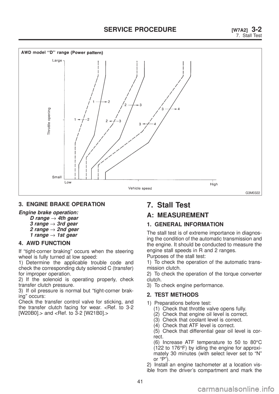
G3M0322
3. ENGINE BRAKE OPERATION
Engine brake operation:
D range
®4th gear
3 range
®3rd gear
2 range
®2nd gear
1 range
®1st gear
4. AWD FUNCTION
If ªtight-corner brakingº occurs when the steering
wheel is fully turned at low speed:
1) Determine the applicable trouble code and
check the corresponding duty solenoid C (transfer)
for improper operation.
2) If the solenoid is operating properly, check
transfer clutch pressure.
3) If oil pressure is normal but ªtight-corner brak-
ingº occurs:
Check the transfer control valve for sticking, and
the transfer clutch facing for wear.
7. Stall Test
A: MEASUREMENT
1. GENERAL INFORMATION
The stall test is of extreme importance in diagnos-
ing the condition of the automatic transmission and
the engine. It should be conducted to measure the
engine stall speeds in R and 2 ranges.
Purposes of the stall test:
1) To check the operation of the automatic trans-
mission clutch.
2) To check the operation of the torque converter
clutch.
3) To check engine performance.
2. TEST METHODS
1) Preparations before test:
(1) Check that throttle valve opens fully.
(2) Check that engine oil level is correct.
(3) Check that coolant level is correct.
(4) Check that ATF level is correct.
(5) Check that differential gear oil level is cor-
rect.
(6) Increase ATF temperature to 50 to 80ÉC
(122 to 176ÉF) by idling the engine for approxi-
mately 30 minutes (with select lever set to ªNº
or ªPº).
2) Install an engine tachometer at a location vis-
ible from the driver's compartment and mark the
41
[W7A2]3-2SERVICE PROCEDURE
7. Stall Test
Page 569 of 1456

G3M0322
3. ENGINE BRAKE OPERATION
Engine brake operation:
D range
®4th gear
3 range
®3rd gear
2 range
®2nd gear
1 range
®1st gear
4. AWD FUNCTION
If ªtight-corner brakingº occurs when the steering
wheel is fully turned at low speed:
1) Determine the applicable trouble code and
check the corresponding duty solenoid C (transfer)
for improper operation.
2) If the solenoid is operating properly, check
transfer clutch pressure.
3) If oil pressure is normal but ªtight-corner brak-
ingº occurs:
Check the transfer control valve for sticking, and
the transfer clutch facing for wear.
7. Stall Test
A: MEASUREMENT
1. GENERAL INFORMATION
The stall test is of extreme importance in diagnos-
ing the condition of the automatic transmission and
the engine. It should be conducted to measure the
engine stall speeds in R and 2 ranges.
Purposes of the stall test:
1) To check the operation of the automatic trans-
mission clutch.
2) To check the operation of the torque converter
clutch.
3) To check engine performance.
2. TEST METHODS
1) Preparations before test:
(1) Check that throttle valve opens fully.
(2) Check that engine oil level is correct.
(3) Check that coolant level is correct.
(4) Check that ATF level is correct.
(5) Check that differential gear oil level is cor-
rect.
(6) Increase ATF temperature to 50 to 80ÉC
(122 to 176ÉF) by idling the engine for approxi-
mately 30 minutes (with select lever set to ªNº
or ªPº).
2) Install an engine tachometer at a location vis-
ible from the driver's compartment and mark the
41
[W7A2]3-2SERVICE PROCEDURE
7. Stall Test
Page 570 of 1456
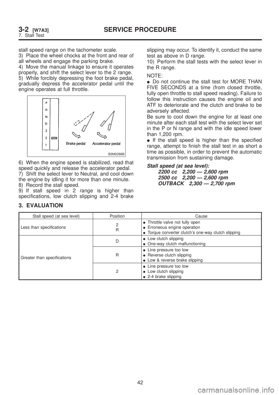
stall speed range on the tachometer scale.
3) Place the wheel chocks at the front and rear of
all wheels and engage the parking brake.
4) Move the manual linkage to ensure it operates
properly, and shift the select lever to the 2 range.
5) While forcibly depressing the foot brake pedal,
gradually depress the accelerator pedal until the
engine operates at full throttle.
B3M0286B
6) When the engine speed is stabilized, read that
speed quickly and release the accelerator pedal.
7) Shift the select lever to Neutral, and cool down
the engine by idling it for more than one minute.
8) Record the stall speed.
9) If stall speed in 2 range is higher than
specifications, low clutch slipping and 2-4 brakeslipping may occur. To identify it, conduct the same
test as above in D range.
10) Perform the stall tests with the select lever in
the R range.
NOTE:
IDo not continue the stall test for MORE THAN
FIVE SECONDS at a time (from closed throttle,
fully open throttle to stall speed reading). Failure to
follow this instruction causes the engine oil and
ATF to deteriorate and the clutch and brake to be
adversely affected.
Be sure to cool down the engine for at least one
minute after each stall test with the select lever set
in the P or N range and with the idle speed lower
than 1,200 rpm.
IIf the stall speed is higher than the specified
range, attempt to finish the stall test in as short a
time as possible, in order to prevent the automatic
transmission from sustaining damage.Stall speed (at sea level):
2200 cc 2,200 Ð 2,600 rpm
2500 cc 2,200 Ð 2,600 rpm
OUTBACK 2,300 Ð 2,700 rpm
3. EVALUATION
Stall speed (at sea level) Position Cause
Less than specifications2
RIThrottle valve not fully open
IErroneous engine operation
ITorque converter clutch's one-way clutch slipping
Greater than specificationsDILow clutch slipping
IOne-way clutch malfunctioning
RILine pressure too low
IReverse clutch slipping
ILow & reverse brake slipping
2ILine pressure too low
ILow clutch slipping
I2-4 brake slipping
42
3-2[W7A3]SERVICE PROCEDURE
7. Stall Test
Page 993 of 1456
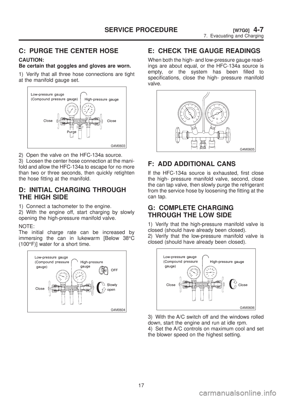
C: PURGE THE CENTER HOSE
CAUTION:
Be certain that goggles and gloves are worn.
1) Verify that all three hose connections are tight
at the manifold gauge set.
G4M0603
2) Open the valve on the HFC-134a source.
3) Loosen the center hose connection at the mani-
fold and allow the HFC-134a to escape for no more
than two or three seconds, then quickly retighten
the hose fitting at the manifold.
D: INITIAL CHARGING THROUGH
THE HIGH SIDE
1) Connect a tachometer to the engine.
2) With the engine off, start charging by slowly
opening the high-pressure manifold valve.
NOTE:
The initial charge rate can be increased by
immersing the can in lukewarm [Below 38ÉC
(100ÉF)] water for a short time.
G4M0604
E: CHECK THE GAUGE READINGS
When both the high- and low-pressure gauge read-
ings are about equal, or the HFC-134a source is
empty, or the system has been filled to
specifications, close the high- pressure manifold
valve.
G4M0605
F: ADD ADDITIONAL CANS
If the HFC-134a source is exhausted, first close
the high- pressure manifold valve, second, close
the can tap valve, then slowly purge the refrigerant
from the service hose by loosening the fitting at the
can tap.
G: COMPLETE CHARGING
THROUGH THE LOW SIDE
1) Verify that the high-pressure manifold valve is
closed (should have already been closed).
2) Verify that the low-pressure manifold valve is
closed (should have already been closed).
G4M0606
3) With the A/C switch off and the windows rolled
down, start the engine and run at idle rpm.
4) Set the A/C controls on maximum cool and set
the blower speed on the highest setting.
17
[W7G0]4-7SERVICE PROCEDURE
7. Evacuating and Charging
Page 1226 of 1456
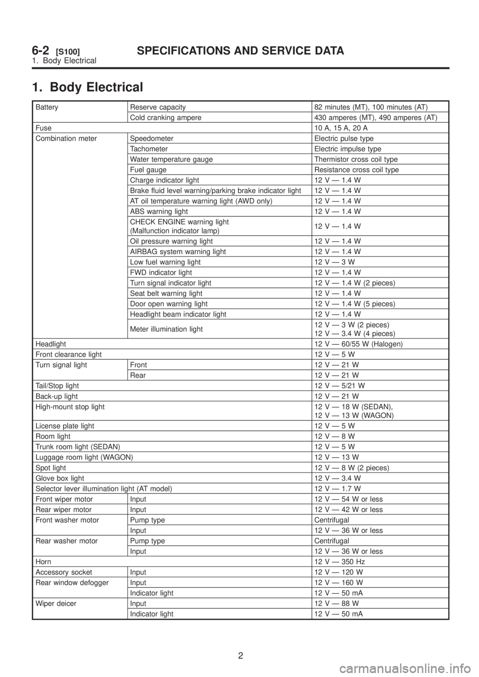
1. Body Electrical
Battery Reserve capacity 82 minutes (MT), 100 minutes (AT)
Cold cranking ampere 430 amperes (MT), 490 amperes (AT)
Fuse10 A, 15 A, 20 A
Combination meter Speedometer Electric pulse type
Tachometer Electric impulse type
Water temperature gauge Thermistor cross coil type
Fuel gauge Resistance cross coil type
Charge indicator light 12 V Ð 1.4 W
Brake fluid level warning/parking brake indicator light 12 V Ð 1.4 W
AT oil temperature warning light (AWD only) 12 V Ð 1.4 W
ABS warning light 12 V Ð 1.4 W
CHECK ENGINE warning light
(Malfunction indicator lamp)12 V Ð 1.4 W
Oil pressure warning light 12 V Ð 1.4 W
AIRBAG system warning light 12 V Ð 1.4 W
Low fuel warning light 12VÐ3W
FWD indicator light 12 V Ð 1.4 W
Turn signal indicator light 12 V Ð 1.4 W (2 pieces)
Seat belt warning light 12 V Ð 1.4 W
Door open warning light 12 V Ð 1.4 W (5 pieces)
Headlight beam indicator light 12 V Ð 1.4 W
Meter illumination light12VÐ3W(2pieces)
12 V Ð 3.4 W (4 pieces)
Headlight12 V Ð 60/55 W (Halogen)
Front clearance light 12VÐ5W
Turn signal light Front 12VÐ21W
Rear 12VÐ21W
Tail/Stop light12 V Ð 5/21 W
Back-up light12VÐ21W
High-mount stop light 12VÐ18W(SEDAN),
12VÐ13W(WAGON)
License plate light 12VÐ5W
Room light12VÐ8W
Trunk room light (SEDAN) 12VÐ5W
Luggage room light (WAGON) 12VÐ13W
Spot light12VÐ8W(2pieces)
Glove box light 12 V Ð 3.4 W
Selector lever illumination light (AT model) 12 V Ð 1.7 W
Front wiper motor Input 12VÐ54Worless
Rear wiper motor Input 12VÐ42Worless
Front washer motor Pump type Centrifugal
Input 12VÐ36Worless
Rear washer motor Pump type Centrifugal
Input 12VÐ36Worless
Horn12 V Ð 350 Hz
Accessory socket Input 12 V Ð 120 W
Rear window defogger Input 12 V Ð 160 W
Indicator light 12VÐ50mA
Wiper deicer Input 12VÐ88W
Indicator light 12VÐ50mA
2
6-2[S100]SPECIFICATIONS AND SERVICE DATA
1. Body Electrical
Page 1256 of 1456
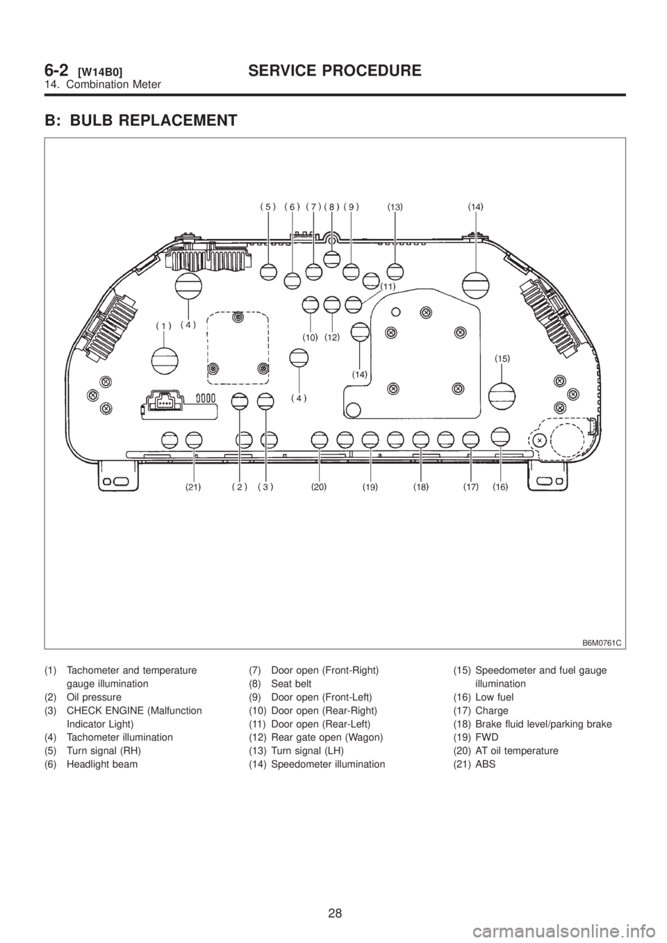
B: BULB REPLACEMENT
B6M0761C
(1) Tachometer and temperature
gauge illumination
(2) Oil pressure
(3) CHECK ENGINE (Malfunction
Indicator Light)
(4) Tachometer illumination
(5) Turn signal (RH)
(6) Headlight beam(7) Door open (Front-Right)
(8) Seat belt
(9) Door open (Front-Left)
(10) Door open (Rear-Right)
(11) Door open (Rear-Left)
(12) Rear gate open (Wagon)
(13) Turn signal (LH)
(14) Speedometer illumination(15) Speedometer and fuel gauge
illumination
(16) Low fuel
(17) Charge
(18) Brake fluid level/parking brake
(19) FWD
(20) AT oil temperature
(21) ABS
28
6-2[W14B0]SERVICE PROCEDURE
14. Combination Meter