Page 1080 of 1456
12. Front Grille
A: REMOVAL AND INSTALLATION
1) Remove four upper clips from body panel. To
facilitate removal, press portion shown in figure
using screwdriver.
B5M0294A
2) Pull front grille to detach it from two lower clips.
(Two lower clips remain on headlight.)
3) Installation is in the reverse order of removal.
NOTE:
Attach all clips to grille. Align them with clip hole in
body and push them into place.
13. Door Mirror
A: REMOVAL AND INSTALLATION
1) Remove the gusset cover.
B6M0146
2) Remove inner remote control switch cover.
B5M0296
3) Remove front door trim.
B5M0297
4) Remove front door trim.
55
[W13A0]5-1SERVICE PROCEDURE
13. Door Mirror
Page 1081 of 1456
12. Front Grille
A: REMOVAL AND INSTALLATION
1) Remove four upper clips from body panel. To
facilitate removal, press portion shown in figure
using screwdriver.
B5M0294A
2) Pull front grille to detach it from two lower clips.
(Two lower clips remain on headlight.)
3) Installation is in the reverse order of removal.
NOTE:
Attach all clips to grille. Align them with clip hole in
body and push them into place.
13. Door Mirror
A: REMOVAL AND INSTALLATION
1) Remove the gusset cover.
B6M0146
2) Remove inner remote control switch cover.
B5M0296
3) Remove front door trim.
B5M0297
4) Remove front door trim.
55
[W13A0]5-1SERVICE PROCEDURE
13. Door Mirror
Page 1082 of 1456
5) Disconnect the door mirror connector.
6) Remove the door mirror installation screws.
B5M0298A
7) Installation is in the reverse order of removal.
14. Side Protector
A: REMOVAL AND INSTALLATION
Side protector consists of three parts; front fender,
front door and rear door.
B5M0411A
1. SIDE PROTECTOR FRONT FENDER
PORTION
1) Remove bracket which secures mud guard to
front fender.
B5M0285A
2) Remove mud guard.
NOTE:
Detach the rear part of mud guard as required for
the procedure. It is not necessary to remove the
entire mud guard.
3) Use pliers to remove a clip from inside front
fender. Remove it from vehicle body but keep it
with side protector.
4) Installation is in the reverse order of removal.
56
5-1[W14A0]SERVICE PROCEDURE
14. Side Protector
Page 1083 of 1456
5) Disconnect the door mirror connector.
6) Remove the door mirror installation screws.
B5M0298A
7) Installation is in the reverse order of removal.
14. Side Protector
A: REMOVAL AND INSTALLATION
Side protector consists of three parts; front fender,
front door and rear door.
B5M0411A
1. SIDE PROTECTOR FRONT FENDER
PORTION
1) Remove bracket which secures mud guard to
front fender.
B5M0285A
2) Remove mud guard.
NOTE:
Detach the rear part of mud guard as required for
the procedure. It is not necessary to remove the
entire mud guard.
3) Use pliers to remove a clip from inside front
fender. Remove it from vehicle body but keep it
with side protector.
4) Installation is in the reverse order of removal.
56
5-1[W14A0]SERVICE PROCEDURE
14. Side Protector
Page 1086 of 1456

16. Sunroof
A: REMOVAL AND INSTALLATION
1. SEDAN AND WAGON REAR (EXCEPT
OUTBACK)
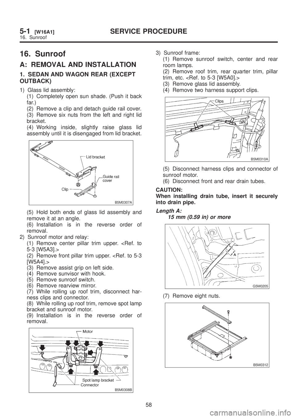
1) Glass lid assembly:
(1) Completely open sun shade. (Push it back
far.)
(2) Remove a clip and detach guide rail cover.
(3) Remove six nuts from the left and right lid
bracket.
(4) Working inside, slightly raise glass lid
assembly until it is disengaged from lid bracket.
B5M0307A
(5) Hold both ends of glass lid assembly and
remove it at an angle.
(6) Installation is in the reverse order of
removal.
2) Sunroof motor and relay:
(1) Remove center pillar trim upper.
5-3 [W5A3].>
(2) Remove front pillar trim upper.
[W5A4].>
(3) Remove assist grip on left side.
(4) Remove sunvisor with hook.
(5) Remove sunroof switch.
(6) Remove rearview mirror.
(7) While rolling up roof trim, disconnect har-
ness clips and connector.
(8) While rolling up roof trim, remove spot lamp
bracket and sunroof motor.
(9) Installation is in the reverse order of
removal.
B5M0308B
3) Sunroof frame:
(1) Remove sunroof switch, center and rear
room lamps.
(2) Remove roof trim, rear quarter trim, pillar
trim, etc.
(3) Remove glass lid assembly.
(4) Remove two harness support clips.
B5M0310A
(5) Disconnect harness clips and connector of
sunroof motor.
(6) Disconnect front and rear drain tubes.
CAUTION:
When installing drain tube, insert it securely
into drain pipe.
Length A:
15 mm (0.59 in) or more
G5M0205
(7) Remove eight nuts.
B5M0312
58
5-1[W16A1]SERVICE PROCEDURE
16. Sunroof
Page 1114 of 1456

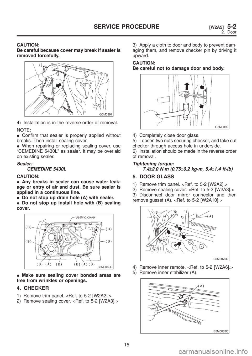
CAUTION:
Be careful because cover may break if sealer is
removed forcefully.
G5M0391
4) Installation is in the reverse order of removal.
NOTE:
IConfirm that sealer is properly applied without
breaks. Then install sealing cover.
IWhen repairing or replacing sealing cover, use
ªCEMEDINE 5430Lº as sealer. It may be overlaid
on existing sealer.
Sealer:
CEMEDINE 5430L
CAUTION:
IAny breaks in sealer can cause water leak-
age or entry of air and dust. Be sure sealer is
applied in a continuous line.
IDo not stop up drain hole (A) with sealer.
IDo not stop up install hole with (B) sealing
cover.
B5M0062C
IMake sure sealing cover bonded areas are
free from wrinkles or openings.
4. CHECKER
1) Remove trim panel.
2) Remove sealing cover. 3) Apply a cloth to door and body to prevent dam-
aging them, and remove checker pin by driving it
upward.
CAUTION:
Be careful not to damage door and body.
G5M0392
4) Completely close door glass.
5) Loosen two nuts securing checker, and take out
checker through access hole in underside.
6) Installation should be made in the reverse order
of removal.
Tightening torque:
7.4
±2.0 N´m (0.75±0.2 kg-m, 5.4±1.4 ft-lb)
5. DOOR GLASS
1) Remove trim panel.
2) Remove sealing cover.
3) Disconnect door mirror connector and then
remove gusset (A).
B5M0070C
4) Remove inner remote.
5) Remove inner stabilizer (A).
B5M0063C
15
[W2A5]5-2SERVICE PROCEDURE
2. Door
Page 1117 of 1456
![SUBARU LEGACY 1999 Service Repair Manual 10. GUSSET
1) Be sure window is all the way down.
2) Remove trim panel. <Ref. to 5-2 [W2A2].>
3) Remove door rearview mirror.
4) Remove sealing cover. <Ref. to 5-2 [W2A3].>
5) Remove bolts and nuts wh SUBARU LEGACY 1999 Service Repair Manual 10. GUSSET
1) Be sure window is all the way down.
2) Remove trim panel. <Ref. to 5-2 [W2A2].>
3) Remove door rearview mirror.
4) Remove sealing cover. <Ref. to 5-2 [W2A3].>
5) Remove bolts and nuts wh](/manual-img/17/57435/w960_57435-1116.png)
10. GUSSET
1) Be sure window is all the way down.
2) Remove trim panel.
3) Remove door rearview mirror.
4) Remove sealing cover.
5) Remove bolts and nuts which secure gusset
(A).
6) Lift out gusset (A).
B5M0070D
7) Installation is in the reverse order of removal.
11. REAR DOOR CATCHER
1) Open the rear door.
2) Using TORXTBIT (Tamper resistant type),
remove rear door catcher.
B5M0467A
3) Installation is in the reverse order of removal.
Tightening torque:
37
±10 N´m (3.8±1.0 kg-m, 27.5±7.2 ft-lb)
B: ADJUSTMENT
1. DOOR ASSEMBLY
1) Using ST, loosen bolts securing upper and
lower hinges to body, and adjust fore-and-aft and
vertical alignment of door.
ST 925610000 DOOR HINGE WRENCH
2) Loosen mounting screws approximately one
rotation. Adjust striker (A) position by lightly tap-
ping with hammer. (To adjust, utilize the shape of
striker nut plate support (B).)
CAUTION:
IUse cloth to prevent damaging body or other
parts.
IDo not directly tap striker plastic portion.
IDo not apply impact on spot-welded striker
nut plate.
Hinge tightening torque (body side):
29
±5 N´m (3.0±0.5 kg-m, 21.7±3.6 ft-lb)
Striker tightening torque:
14
±4 N´m (1.4±0.4 kg-m, 10.1±2.9 ft-lb)
B5M0071C
18
5-2[W2A10]SERVICE PROCEDURE
2. Door
Page 1138 of 1456

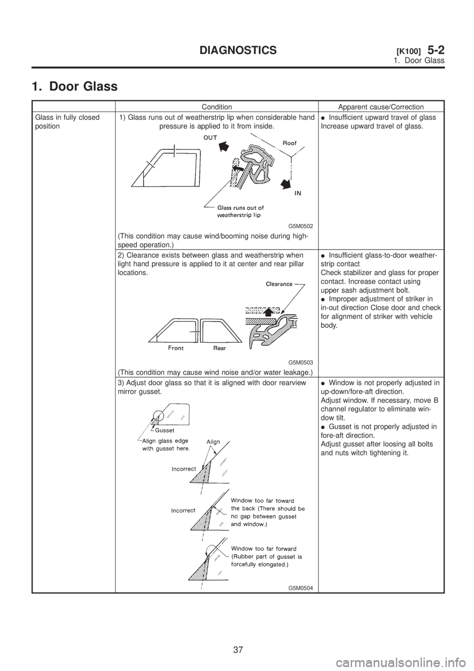
1. Door Glass
Condition Apparent cause/Correction
Glass in fully closed
position1) Glass runs out of weatherstrip lip when considerable hand
pressure is applied to it from inside.
G5M0502
IInsufficient upward travel of glass
Increase upward travel of glass.
(This condition may cause wind/booming noise during high-
speed operation.)
2) Clearance exists between glass and weatherstrip when
light hand pressure is applied to it at center and rear pillar
locations.
G5M0503
IInsufficient glass-to-door weather-
strip contact
Check stabilizer and glass for proper
contact. Increase contact using
upper sash adjustment bolt.
IImproper adjustment of striker in
in-out direction Close door and check
for alignment of striker with vehicle
body.
(This condition may cause wind noise and/or water leakage.)
3) Adjust door glass so that it is aligned with door rearview
mirror gusset.
G5M0504
IWindow is not properly adjusted in
up-down/fore-aft direction.
Adjust window. If necessary, move B
channel regulator to eliminate win-
dow tilt.
IGusset is not properly adjusted in
fore-aft direction.
Adjust gusset after loosing all bolts
and nuts witch tightening it.
37
[K100]5-2DIAGNOSTICS
1. Door Glass