Page 431 of 1456
A: DIAGNOSTIC DIAGRAM OF CLUTCH DRAG
B2M1012A
20
2-10[K1A0]DIAGNOSTICS
1. Clutch System
Page 1200 of 1456
B6M0489A
2) Diodes on ªþº side
Continuity of proper diodes on ªþº side
Terminal N, U, V
and WªEº side
(+) (þ)
(+) ÐContinuity must
exist.
(þ)Continuity must
not exist.Ð
B6M0490A
5. IC REGULATOR
1) Compose a circuit diagram as shown in figure.
B6M0491B
(1) Voltage meter: 0 to 30 V
(2) Switch 1
(3) Variable DC power supply: Variable 0 to 20 V, 1 A
or more
(4) Lamp 2
(5) Lamp 1
(6) Switch 3
(7) Switch 2
(8) Plus generator: Power supply 5 to 30 V, 1 kHz
2) Check operation as shown in chart below.
No.Switch operation
Value of volt-
age meterLamp operation
Remarks
123 12
1 ON OFF OFF 12 V DIM ON Check initial excitation.
2 ON ON OFF 12 V ON or BLINK OFF Check total excitation.
3 ON ON OFF 16 VOFF or DIM-
BLINKOFFWhen value of voltage
meter is between 12 V
and 16 V.
4 OFF ON OFF 12 V ON or BLINK ONCheck connection for
S and B terminals.
5 OFF ON ON 18 V ON ONCheck for over loading
of voltage.
19
[W2C5]6-1SERVICE PROCEDURE
2. Generator
Page 1280 of 1456
1. General Description
A: WIRING DIAGRAM
The wiring diagram of each system is illustrated so
that you can understand the path through which
the electric current flows from the battery.
Sketches and codes are used in the diagrams.
They should read as follows:
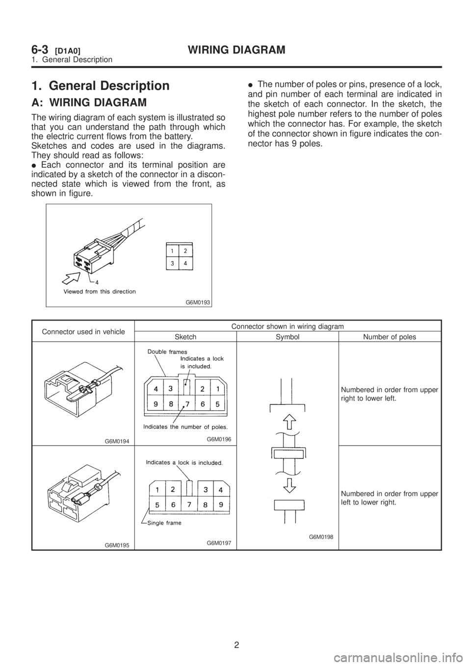
IEach connector and its terminal position are
indicated by a sketch of the connector in a discon-
nected state which is viewed from the front, as
shown in figure.
G6M0193
IThe number of poles or pins, presence of a lock,
and pin number of each terminal are indicated in
the sketch of each connector. In the sketch, the
highest pole number refers to the number of poles
which the connector has. For example, the sketch
of the connector shown in figure indicates the con-
nector has 9 poles.
Connector used in vehicleConnector shown in wiring diagram
Sketch Symbol Number of poles
G6M0194G6M0196
G6M0198
Numbered in order from upper
right to lower left.
G6M0195G6M0197
Numbered in order from upper
left to lower right.
2
6-3[D1A0]WIRING DIAGRAM
1. General Description
Page 1281 of 1456
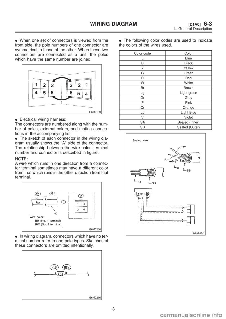
IWhen one set of connectors is viewed from the
front side, the pole numbers of one connector are
symmetrical to those of the other. When these two
connectors are connected as a unit, the poles
which have the same number are joined.
G6M0199
IElectrical wiring harness:
The connectors are numbered along with the num-
ber of poles, external colors, and mating connec-
tions in the accompanying list.
IThe sketch of each connector in the wiring dia-
gram usually shows the ªAº side of the connector.
The relationship between the wire color, terminal
number and connector is described in figure.
NOTE:
A wire which runs in one direction from a connec-
tor terminal sometimes may have a different color
from that which runs in the other direction from that
terminal.
G6M0200
IIn wiring diagram, connectors which have no ter-
minal number refer to one-pole types. Sketches of
these connectors are omitted intentionally.
G6M0216
IThe following color codes are used to indicate
the colors of the wires used.
Color code Color
L Blue
B Black
Y Yellow
G Green
R Red
W White
Br Brown
Lg Light green
Gr Gray
P Pink
Or Orange
Lb Light Blue
V Violet
SA Sealed (Inner)
SB Sealed (Outer)
G6M0201
3
[D1A0]6-3WIRING DIAGRAM
1. General Description
Page 1282 of 1456
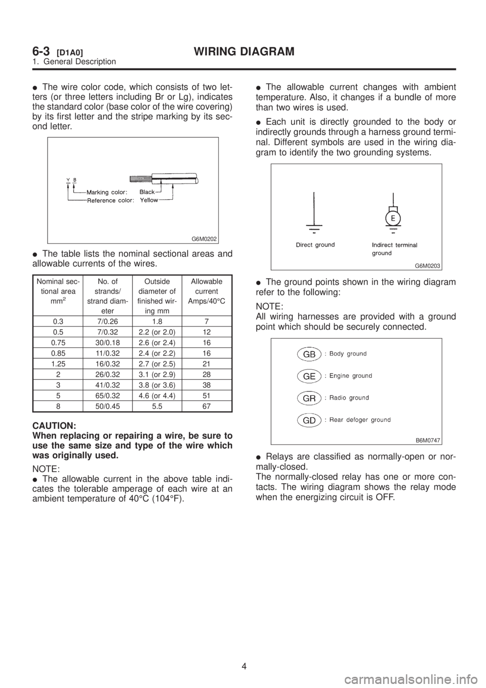
IThe wire color code, which consists of two let-
ters (or three letters including Br or Lg), indicates
the standard color (base color of the wire covering)
by its first letter and the stripe marking by its sec-
ond letter.
G6M0202
IThe table lists the nominal sectional areas and
allowable currents of the wires.
Nominal sec-
tional area
mm
2
No. of
strands/
strand diam-
eterOutside
diameter of
finished wir-
ing mmAllowable
current
Amps/40ÉC
0.3 7/0.26 1.8 7
0.5 7/0.32 2.2 (or 2.0) 12
0.75 30/0.18 2.6 (or 2.4) 16
0.85 11/0.32 2.4 (or 2.2) 16
1.25 16/0.32 2.7 (or 2.5) 21
2 26/0.32 3.1 (or 2.9) 28
3 41/0.32 3.8 (or 3.6) 38
5 65/0.32 4.6 (or 4.4) 51
8 50/0.45 5.5 67
CAUTION:
When replacing or repairing a wire, be sure to
use the same size and type of the wire which
was originally used.
NOTE:
IThe allowable current in the above table indi-
cates the tolerable amperage of each wire at an
ambient temperature of 40ÉC (104ÉF).IThe allowable current changes with ambient
temperature. Also, it changes if a bundle of more
than two wires is used.
IEach unit is directly grounded to the body or
indirectly grounds through a harness ground termi-
nal. Different symbols are used in the wiring dia-
gram to identify the two grounding systems.
G6M0203
IThe ground points shown in the wiring diagram
refer to the following:
NOTE:
All wiring harnesses are provided with a ground
point which should be securely connected.
B6M0747
IRelays are classified as normally-open or nor-
mally-closed.
The normally-closed relay has one or more con-
tacts. The wiring diagram shows the relay mode
when the energizing circuit is OFF.
4
6-3[D1A0]WIRING DIAGRAM
1. General Description
Page 1283 of 1456
B6M0748
5
[D1A0]6-3WIRING DIAGRAM
1. General Description
Page 1284 of 1456
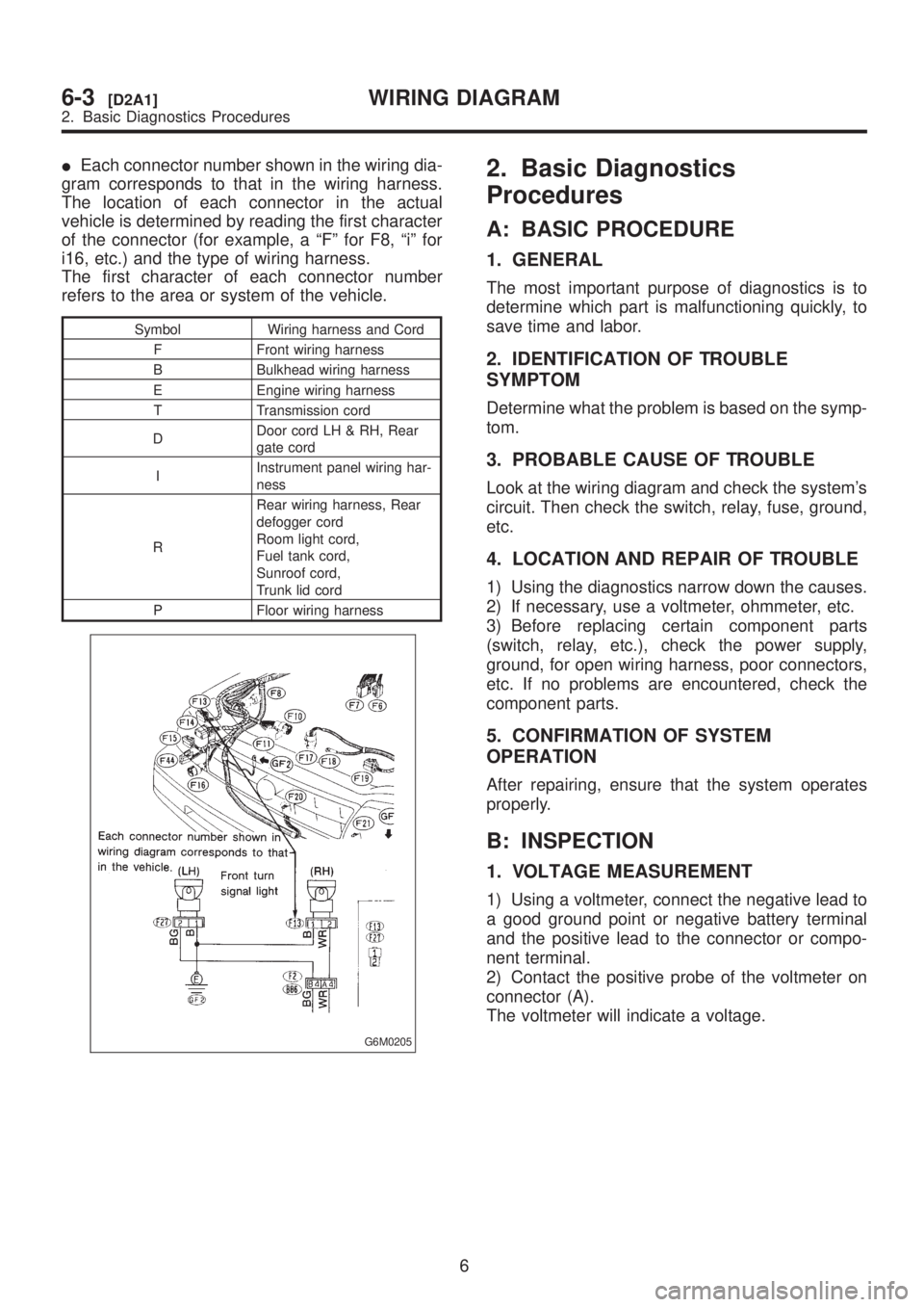
IEach connector number shown in the wiring dia-
gram corresponds to that in the wiring harness.
The location of each connector in the actual
vehicle is determined by reading the first character
of the connector (for example, a ªFº for F8, ªiº for
i16, etc.) and the type of wiring harness.
The first character of each connector number
refers to the area or system of the vehicle.
Symbol Wiring harness and Cord
F Front wiring harness
B Bulkhead wiring harness
E Engine wiring harness
T Transmission cord
DDoor cord LH & RH, Rear
gate cord
IInstrument panel wiring har-
ness
RRear wiring harness, Rear
defogger cord
Room light cord,
Fuel tank cord,
Sunroof cord,
Trunk lid cord
P Floor wiring harness
G6M0205
2. Basic Diagnostics
Procedures
A: BASIC PROCEDURE
1. GENERAL
The most important purpose of diagnostics is to
determine which part is malfunctioning quickly, to
save time and labor.
2. IDENTIFICATION OF TROUBLE
SYMPTOM
Determine what the problem is based on the symp-
tom.
3. PROBABLE CAUSE OF TROUBLE
Look at the wiring diagram and check the system's
circuit. Then check the switch, relay, fuse, ground,
etc.
4. LOCATION AND REPAIR OF TROUBLE
1) Using the diagnostics narrow down the causes.
2) If necessary, use a voltmeter, ohmmeter, etc.
3) Before replacing certain component parts
(switch, relay, etc.), check the power supply,
ground, for open wiring harness, poor connectors,
etc. If no problems are encountered, check the
component parts.
5. CONFIRMATION OF SYSTEM
OPERATION
After repairing, ensure that the system operates
properly.
B: INSPECTION
1. VOLTAGE MEASUREMENT
1) Using a voltmeter, connect the negative lead to
a good ground point or negative battery terminal
and the positive lead to the connector or compo-
nent terminal.
2) Contact the positive probe of the voltmeter on
connector (A).
The voltmeter will indicate a voltage.
6
6-3[D2A1]WIRING DIAGRAM
2. Basic Diagnostics Procedures
Page 1285 of 1456
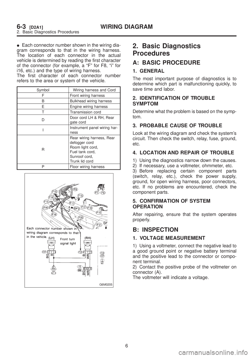
IEach connector number shown in the wiring dia-
gram corresponds to that in the wiring harness.
The location of each connector in the actual
vehicle is determined by reading the first character
of the connector (for example, a ªFº for F8, ªiº for
i16, etc.) and the type of wiring harness.
The first character of each connector number
refers to the area or system of the vehicle.
Symbol Wiring harness and Cord
F Front wiring harness
B Bulkhead wiring harness
E Engine wiring harness
T Transmission cord
DDoor cord LH & RH, Rear
gate cord
IInstrument panel wiring har-
ness
RRear wiring harness, Rear
defogger cord
Room light cord,
Fuel tank cord,
Sunroof cord,
Trunk lid cord
P Floor wiring harness
G6M0205
2. Basic Diagnostics
Procedures
A: BASIC PROCEDURE
1. GENERAL
The most important purpose of diagnostics is to
determine which part is malfunctioning quickly, to
save time and labor.
2. IDENTIFICATION OF TROUBLE
SYMPTOM
Determine what the problem is based on the symp-
tom.
3. PROBABLE CAUSE OF TROUBLE
Look at the wiring diagram and check the system's
circuit. Then check the switch, relay, fuse, ground,
etc.
4. LOCATION AND REPAIR OF TROUBLE
1) Using the diagnostics narrow down the causes.
2) If necessary, use a voltmeter, ohmmeter, etc.
3) Before replacing certain component parts
(switch, relay, etc.), check the power supply,
ground, for open wiring harness, poor connectors,
etc. If no problems are encountered, check the
component parts.
5. CONFIRMATION OF SYSTEM
OPERATION
After repairing, ensure that the system operates
properly.
B: INSPECTION
1. VOLTAGE MEASUREMENT
1) Using a voltmeter, connect the negative lead to
a good ground point or negative battery terminal
and the positive lead to the connector or compo-
nent terminal.
2) Contact the positive probe of the voltmeter on
connector (A).
The voltmeter will indicate a voltage.
6
6-3[D2A1]WIRING DIAGRAM
2. Basic Diagnostics Procedures