Page 427 of 1456
6. Master Cylinder and
Reservoir Tank
A: REMOVAL
1) Thoroughly drain brake fluid from reservoir
tank.
2) Remove snap pin, clevis pin and separate push
rod of master cylinder from clutch pedal.
B4M1189A
3) Remove clutch pipe from master cylinder.
4) Remove master cylinder with reservoir tank.
CAUTION:
Be extremely careful not to spill brake fluid.
Brake fluid spilt on the vehicle body will harm
the paint surface; wipe it off quickly if spilt.
S2M0352A
B: DISASSEMBLY
1) Remove straight pin and reservoir tank.
S2M0356A
2) Remove oil seal.
S2M0357A
3) Move the cylinder boot backward.
S2M0358A
4) Remove snap ring.
CAUTION:
Be careful when removing the snap ring to pre-
vent the rod, washer, piston and return spring
from flying out.
5) Remove damper cylinder from master cylinder
body.
S2M0359A
16
2-10[W6A0]SERVICE PROCEDURE
6. Master Cylinder and Reservoir Tank
Page 639 of 1456
1. Manual Transmission
A: AWD MODEL
B3M0607B
(1) Gear shift knob
(2) Console boot
(3) Boot plate
(4) Gear shift lever
(5) Bush
(6) Spacer
(7) Locking wire
(8) Boot
(9) Snap ring
(10) O-ring(11) Bush (Shift lever)
(12) Cushion rubber
(13) Bush (Stay rear)
(14) Joint
(15) Rod
(16) Bracket
(17) Spring
(18) Washer
(19) Stay
(20) Bush (Stay front)Tightening torque: N´m (kg-m, ft-lb)
T1:
4.4±1.5 (0.45±0.15, 3.3±1.1)
T2:5 (0.51, 3.7)
T3:12±3 (1.2±0.3, 8.7±2.2)
T4:18±5 (1.8±0.5, 13.0±3.6)
T5:24.5±2 (2.50±0.20,
18.07
±1.48)
2
3-3[C1A0]COMPONENT PARTS
1. Manual Transmission
Page 640 of 1456
B: FWD MODEL
B3M0606B
(1) Gear shift knob
(2) Console boot
(3) Boot plate
(4) Gear shift lever
(5) Bush
(6) Spacer
(7) Locking wire
(8) Boot
(9) Snap ring(10) O-ring
(11) Bush (Shift lever)
(12) Cushion rubber
(13) Bush (Stay rear)
(14) Joint
(15) Rod
(16) Bracket
(17) Spring
(18) Stay(19) Bush (Stay front)
Tightening torque: N´m (kg-m, ft-lb)
T1:
4.4±1.5 (0.45±0.15, 3.3±1.1)
T2:5 (0.51, 3.7)
T3:12±3 (1.2±0.3, 8.7±2.2)
T4:18±5 (1.8±0.5, 13.0±3.6)
T5:29±5 (3.0±0.5, 21.7±3.6)
3
[C1B0]3-3COMPONENT PARTS
1. Manual Transmission
Page 642 of 1456
1. Manual Transmission
A: REMOVAL
1) Remove console box.
2) Remove boot plate from the body.
B3M0615
3) Remove the spring between the joint and
bracket.
G3M0680
4) Remove stay from bracket.
G3M0681
5) Remove rod from joint.
B3M0616A
6) Remove gearshift lever.
G3M0683
7) Remove the exhaust cover and remove cush-
ion rubber from the body.
G3M0684
B: DISASSEMBLY
1) Disconnect locking wire.
B3M0617A
2) Remove rod from gearshift lever.
B3M0618A
5
[W1B0]3-3SERVICE PROCEDURE
1. Manual Transmission
Page 643 of 1456
3) Remove snap ring, then disconnect gearshift
lever from stay.
4) Remove boot from gearshift lever.
B3M0619A
5) Remove O-ring, then disconnect bush (Stay
rear).
B3M0620A
6) Draw out spring pin, then remove bush (Shift
lever) from gearshift lever.
B3M0621A
C: INSPECTION
Check each parts (Bush, cushion, spacer, boot,
spring, stay and rod etc.) for deformation, damage
and wear. Repair or replace any defective parts.
Determine defective parts by comparing with new
parts.
B3M0622A
D: ASSEMBLY
1) Clean all parts before assembly.
2) Mount the following parts on the stay.
B3M0830A
(A) Cushion rubber
(B) Bush (Stay front)
6
3-3[W1C0]SERVICE PROCEDURE
1. Manual Transmission
Page 644 of 1456
![SUBARU LEGACY 1999 Service Repair Manual 3) Mount each parts (Boot, O-ring, bush and
spacer) on the gearshift lever.
CAUTION:
IAlways use new O-rings.
IApply grease [NIGTIGHT LYW No.2 or
equivalent] to the inner and side surfaces of
the bush SUBARU LEGACY 1999 Service Repair Manual 3) Mount each parts (Boot, O-ring, bush and
spacer) on the gearshift lever.
CAUTION:
IAlways use new O-rings.
IApply grease [NIGTIGHT LYW No.2 or
equivalent] to the inner and side surfaces of
the bush](/manual-img/17/57435/w960_57435-643.png)
3) Mount each parts (Boot, O-ring, bush and
spacer) on the gearshift lever.
CAUTION:
IAlways use new O-rings.
IApply grease [NIGTIGHT LYW No.2 or
equivalent] to the inner and side surfaces of
the bush when installing spacer.
B3M0623A
4) Insert the gearshift lever into the boot hole.
5) Mount gearshift lever on the stay.
6) Install snap ring to the bottom of the bush (Stay
rear).
B3M0619A
7) Tighten with locking wire to the extent that the
boot will not come off.
CAUTION:
Always use new locking wire.
B3M0617A
8) Insert the rod into the boot hole.9) Connect rod to gearshift lever.
Tightening torque:
12
±3 N´m (1.2±0.3 kg-m, 8.7±2.2 ft-lb)
Rocking torque:
0.74
±0.25 N´m (0.075±0.025 kg-m,
0.54
±0.18 ft-lb) or less
B3M0618A
10) Check that there is no excessive play and that
parts move smoothly.
E: INSTALLATION
1) Put into gearshift lever from passenger com-
partment.
2) Mount boot plate on the body.
3) Install console box and gearshift knob.
5-4 [W1B0].>
B3M0010
4) Mount cushion rubber on the body.
Tightening torque:
18
±5 N´m (1.84±0.51 kg-m, 13.3±3.7 ft-lb)
G3M0684
7
[W1E0]3-3SERVICE PROCEDURE
1. Manual Transmission
Page 662 of 1456

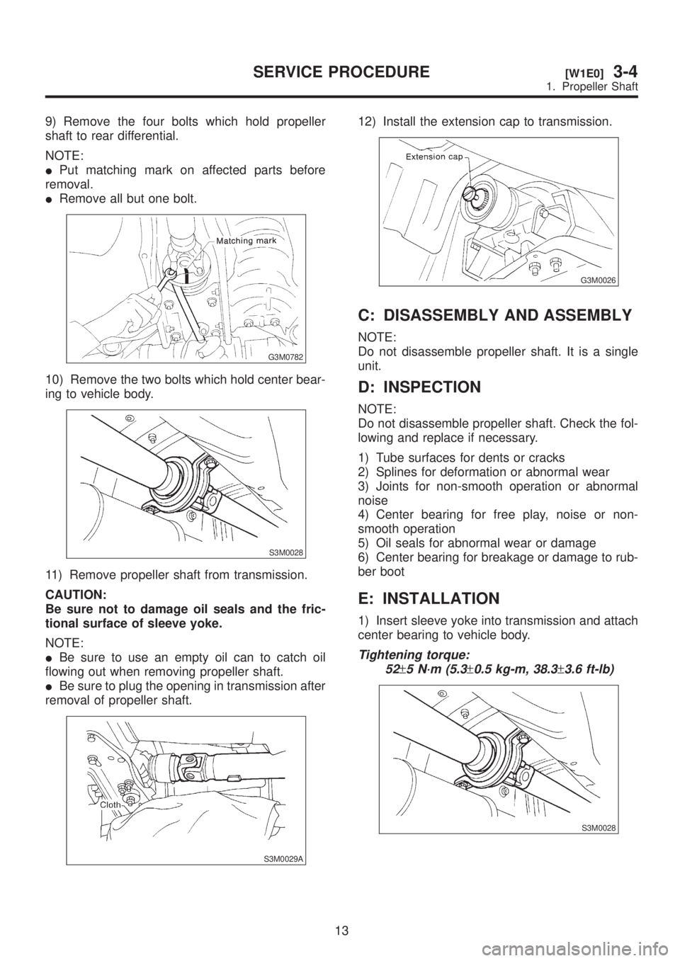
9) Remove the four bolts which hold propeller
shaft to rear differential.
NOTE:
IPut matching mark on affected parts before
removal.
IRemove all but one bolt.
G3M0782
10) Remove the two bolts which hold center bear-
ing to vehicle body.
S3M0028
11) Remove propeller shaft from transmission.
CAUTION:
Be sure not to damage oil seals and the fric-
tional surface of sleeve yoke.
NOTE:
IBe sure to use an empty oil can to catch oil
flowing out when removing propeller shaft.
IBe sure to plug the opening in transmission after
removal of propeller shaft.
S3M0029A
12) Install the extension cap to transmission.
G3M0026
C: DISASSEMBLY AND ASSEMBLY
NOTE:
Do not disassemble propeller shaft. It is a single
unit.
D: INSPECTION
NOTE:
Do not disassemble propeller shaft. Check the fol-
lowing and replace if necessary.
1) Tube surfaces for dents or cracks
2) Splines for deformation or abnormal wear
3) Joints for non-smooth operation or abnormal
noise
4) Center bearing for free play, noise or non-
smooth operation
5) Oil seals for abnormal wear or damage
6) Center bearing for breakage or damage to rub-
ber boot
E: INSTALLATION
1) Insert sleeve yoke into transmission and attach
center bearing to vehicle body.
Tightening torque:
52
±5 N´m (5.3±0.5 kg-m, 38.3±3.6 ft-lb)
S3M0028
13
[W1E0]3-4SERVICE PROCEDURE
1. Propeller Shaft
Page 712 of 1456

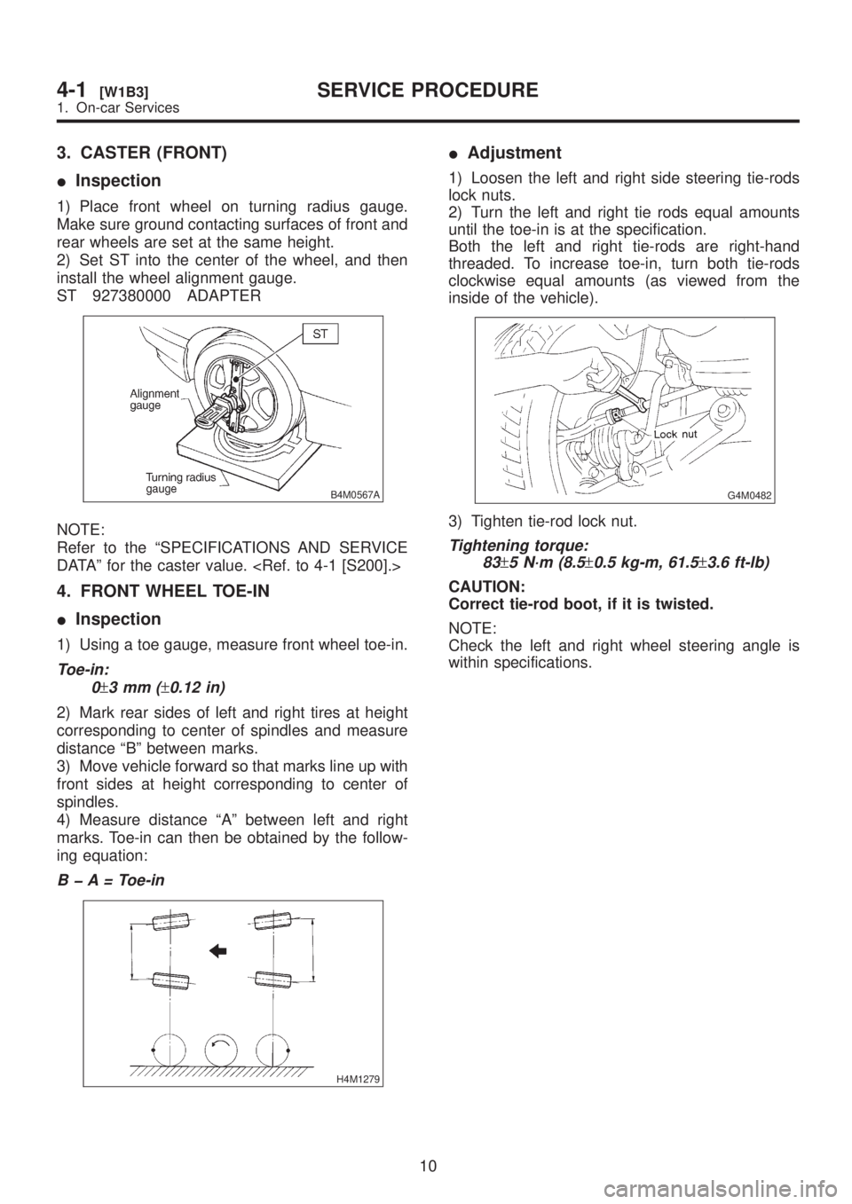
3. CASTER (FRONT)
IInspection
1) Place front wheel on turning radius gauge.
Make sure ground contacting surfaces of front and
rear wheels are set at the same height.
2) Set ST into the center of the wheel, and then
install the wheel alignment gauge.
ST 927380000 ADAPTER
B4M0567A
NOTE:
Refer to the ªSPECIFICATIONS AND SERVICE
DATAº for the caster value.
4. FRONT WHEEL TOE-IN
IInspection
1) Using a toe gauge, measure front wheel toe-in.
Toe-in:
0
±3mm(±0.12 in)
2) Mark rear sides of left and right tires at height
corresponding to center of spindles and measure
distance ªBº between marks.
3) Move vehicle forward so that marks line up with
front sides at height corresponding to center of
spindles.
4) Measure distance ªAº between left and right
marks. Toe-in can then be obtained by the follow-
ing equation:
B þ A = Toe-in
H4M1279
IAdjustment
1) Loosen the left and right side steering tie-rods
lock nuts.
2) Turn the left and right tie rods equal amounts
until the toe-in is at the specification.
Both the left and right tie-rods are right-hand
threaded. To increase toe-in, turn both tie-rods
clockwise equal amounts (as viewed from the
inside of the vehicle).
G4M0482
3) Tighten tie-rod lock nut.
Tightening torque:
83
±5 N´m (8.5±0.5 kg-m, 61.5±3.6 ft-lb)
CAUTION:
Correct tie-rod boot, if it is twisted.
NOTE:
Check the left and right wheel steering angle is
within specifications.
10
4-1[W1B3]SERVICE PROCEDURE
1. On-car Services