Page 115 of 1456

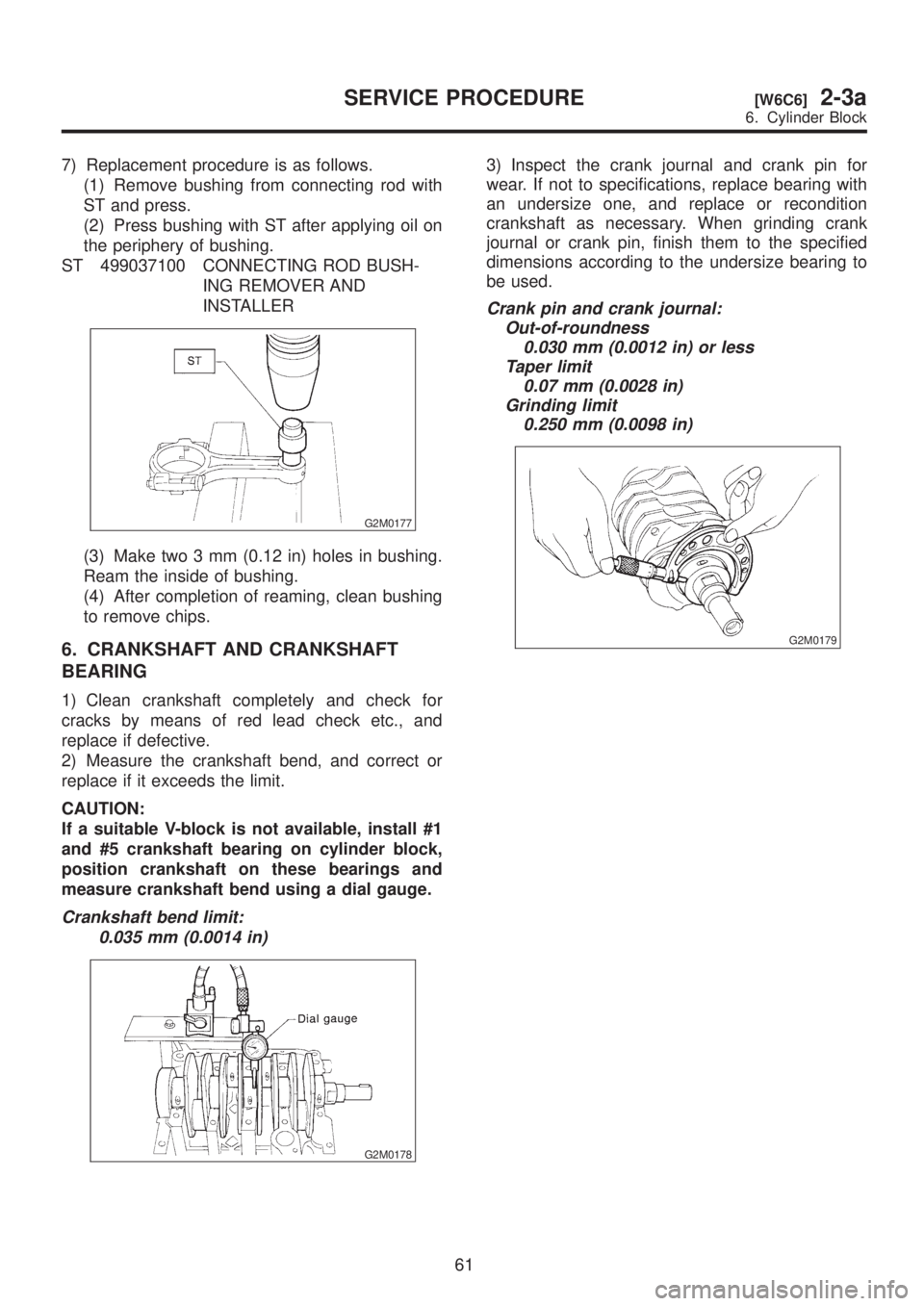
7) Replacement procedure is as follows.
(1) Remove bushing from connecting rod with
ST and press.
(2) Press bushing with ST after applying oil on
the periphery of bushing.
ST 499037100 CONNECTING ROD BUSH-
ING REMOVER AND
INSTALLER
G2M0177
(3) Make two 3 mm (0.12 in) holes in bushing.
Ream the inside of bushing.
(4) After completion of reaming, clean bushing
to remove chips.
6. CRANKSHAFT AND CRANKSHAFT
BEARING
1) Clean crankshaft completely and check for
cracks by means of red lead check etc., and
replace if defective.
2) Measure the crankshaft bend, and correct or
replace if it exceeds the limit.
CAUTION:
If a suitable V-block is not available, install #1
and #5 crankshaft bearing on cylinder block,
position crankshaft on these bearings and
measure crankshaft bend using a dial gauge.
Crankshaft bend limit:
0.035 mm (0.0014 in)
G2M0178
3) Inspect the crank journal and crank pin for
wear. If not to specifications, replace bearing with
an undersize one, and replace or recondition
crankshaft as necessary. When grinding crank
journal or crank pin, finish them to the specified
dimensions according to the undersize bearing to
be used.
Crank pin and crank journal:
Out-of-roundness
0.030 mm (0.0012 in) or less
Taper limit
0.07 mm (0.0028 in)
Grinding limit
0.250 mm (0.0098 in)
G2M0179
61
[W6C6]2-3aSERVICE PROCEDURE
6. Cylinder Block
Page 191 of 1456

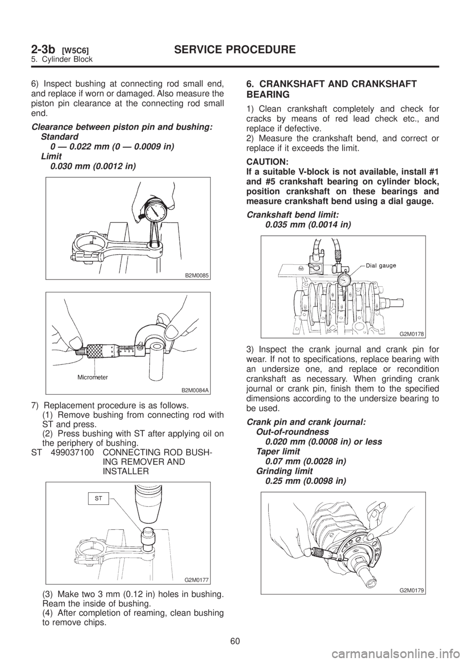
6) Inspect bushing at connecting rod small end,
and replace if worn or damaged. Also measure the
piston pin clearance at the connecting rod small
end.
Clearance between piston pin and bushing:
Standard
0 Ð 0.022 mm (0 Ð 0.0009 in)
Limit
0.030 mm (0.0012 in)
B2M0085
B2M0084A
7) Replacement procedure is as follows.
(1) Remove bushing from connecting rod with
ST and press.
(2) Press bushing with ST after applying oil on
the periphery of bushing.
ST 499037100 CONNECTING ROD BUSH-
ING REMOVER AND
INSTALLER
G2M0177
(3) Make two 3 mm (0.12 in) holes in bushing.
Ream the inside of bushing.
(4) After completion of reaming, clean bushing
to remove chips.
6. CRANKSHAFT AND CRANKSHAFT
BEARING
1) Clean crankshaft completely and check for
cracks by means of red lead check etc., and
replace if defective.
2) Measure the crankshaft bend, and correct or
replace if it exceeds the limit.
CAUTION:
If a suitable V-block is not available, install #1
and #5 crankshaft bearing on cylinder block,
position crankshaft on these bearings and
measure crankshaft bend using a dial gauge.
Crankshaft bend limit:
0.035 mm (0.0014 in)
G2M0178
3) Inspect the crank journal and crank pin for
wear. If not to specifications, replace bearing with
an undersize one, and replace or recondition
crankshaft as necessary. When grinding crank
journal or crank pin, finish them to the specified
dimensions according to the undersize bearing to
be used.
Crank pin and crank journal:
Out-of-roundness
0.020 mm (0.0008 in) or less
Taper limit
0.07 mm (0.0028 in)
Grinding limit
0.25 mm (0.0098 in)
G2M0179
60
2-3b[W5C6]SERVICE PROCEDURE
5. Cylinder Block
Page 349 of 1456
2) Open fuel flap lid, and remove fuel filler cap.
B2M1746
3) Disconnect battery ground cable.
B2M1723
4) Disconnect connector from fuel injector.
G2M0398
5) Remove fuel injector from fuel pipe assembly.
G2M0431
6) Installation is in the reverse order of removal.
CAUTION:
Replace O-rings and insulator.
Tightening torque:
T: 3.4
±0.5 N´m (0.35±0.05 kg-m, 2.5±0.4
ft-lb)
B2M0169C
(A) O-ring B
(B) O-ring A
(C) Fuel injector
(D) Insulator
(E) Fuel injector cup
H: Replacement part
84
2-7[W14A3]SERVICE PROCEDURE
14. Fuel Injector
Page 383 of 1456
![SUBARU LEGACY 1999 Service Repair Manual 4. Fuel Filter
A: REMOVAL
1) Release fuel pressure. <Ref. to 2-8 [W1B0].>
2) Disconnect fuel delivery hoses from fuel filter.
S2M0195
3) Remove filter from holder.
B: INSPECTION
1) Check the inside of SUBARU LEGACY 1999 Service Repair Manual 4. Fuel Filter
A: REMOVAL
1) Release fuel pressure. <Ref. to 2-8 [W1B0].>
2) Disconnect fuel delivery hoses from fuel filter.
S2M0195
3) Remove filter from holder.
B: INSPECTION
1) Check the inside of](/manual-img/17/57435/w960_57435-382.png)
4. Fuel Filter
A: REMOVAL
1) Release fuel pressure.
2) Disconnect fuel delivery hoses from fuel filter.
S2M0195
3) Remove filter from holder.
B: INSPECTION
1) Check the inside of fuel filter for dirt and water
sediment.
2) If it is clogged, or if replacement interval has
been reached, replace it.
3) If water is found in it, shake and expel the water
from inlet port.
C: INSTALLATION
CAUTION:
IIf fuel hoses are damaged at the connecting
portion, replace it with a new one.
IIf clamps are badly damaged, replace with
new ones.
1) Installation is in the reverse order of removal.
2) Tighten hose clamp screws.
Tightening torque:
1.0+0.5/þ0N´m (0.1+0.05/þ0kg-m, 0.7+0.4/þ0ft-lb)
S2M0195
5. Fuel Pump
A: REMOVAL
1) Release fuel pressure.
2) Disconnect fuel delivery hose (A), return hose
(B) and jet pump hose (C) (AWD model only).
B2M0048B
3) Remove nuts which install fuel pump assembly
onto fuel tank.
G2M0343
4) Take off fuel pump from fuel tank.
G2M0344
21
[W5A0]2-8SERVICE PROCEDURE
5. Fuel Pump
Page 384 of 1456
![SUBARU LEGACY 1999 Service Repair Manual 4. Fuel Filter
A: REMOVAL
1) Release fuel pressure. <Ref. to 2-8 [W1B0].>
2) Disconnect fuel delivery hoses from fuel filter.
S2M0195
3) Remove filter from holder.
B: INSPECTION
1) Check the inside of SUBARU LEGACY 1999 Service Repair Manual 4. Fuel Filter
A: REMOVAL
1) Release fuel pressure. <Ref. to 2-8 [W1B0].>
2) Disconnect fuel delivery hoses from fuel filter.
S2M0195
3) Remove filter from holder.
B: INSPECTION
1) Check the inside of](/manual-img/17/57435/w960_57435-383.png)
4. Fuel Filter
A: REMOVAL
1) Release fuel pressure.
2) Disconnect fuel delivery hoses from fuel filter.
S2M0195
3) Remove filter from holder.
B: INSPECTION
1) Check the inside of fuel filter for dirt and water
sediment.
2) If it is clogged, or if replacement interval has
been reached, replace it.
3) If water is found in it, shake and expel the water
from inlet port.
C: INSTALLATION
CAUTION:
IIf fuel hoses are damaged at the connecting
portion, replace it with a new one.
IIf clamps are badly damaged, replace with
new ones.
1) Installation is in the reverse order of removal.
2) Tighten hose clamp screws.
Tightening torque:
1.0+0.5/þ0N´m (0.1+0.05/þ0kg-m, 0.7+0.4/þ0ft-lb)
S2M0195
5. Fuel Pump
A: REMOVAL
1) Release fuel pressure.
2) Disconnect fuel delivery hose (A), return hose
(B) and jet pump hose (C) (AWD model only).
B2M0048B
3) Remove nuts which install fuel pump assembly
onto fuel tank.
G2M0343
4) Take off fuel pump from fuel tank.
G2M0344
21
[W5A0]2-8SERVICE PROCEDURE
5. Fuel Pump
Page 429 of 1456

7. Brake Fluid
A: REPLACEMENT
CAUTION:
IThe FMVSS No. 116, fresh DOT3 or 4 brake
fluid must be used.
ICover bleeder with waste cloth, when loos-
ening it, to prevent brake fluid from being
splashed over surrounding parts.
IAvoid mixing different brands of brake fluid
to prevent degrading the quality of the fluid.
IBe careful not to allow dirt or dust to get into
the reservoir tank.
NOTE:
IDuring bleeding operation, keep the clutch
reserve tank filled with brake fluid to eliminate entry
of air.
IClutch pedal operating must be very slow.
IFor convenience and safety, it is advisable to
have two man working.IThe amount of brake fluid required is approxi-
mately 70 m(2.4 US fl oz, 2.5 Imp fl oz) for total
clutch system.
1) Either jack-up vehicle and place a safety stand
under it, or lift-up vehicle.
2) Remove both front and rear wheels.
3) Draw out the brake fluid from reserve tank with
syringe.
4) Refill reservoir tank with recommended brake
fluid.
Recommended brake fluid:
FMVSS No. 116, fresh DOT3 or 4 brake
fluid
5) Bleed air from oil line with the help of a co-
worker.
18
2-10[W7A0]SERVICE PROCEDURE
7. Brake Fluid
Page 720 of 1456
(3) Calculate plays from the following formula.
S=
2þ1(4) When plays are larger than the following
value, replace with a new one.
FRONT BALL JOINT
Specified play for replacement:
Less than 0.3 mm (0.012 in)
2) When play is smaller than the specified value,
visually inspect the dust cover.
3) If the dust cover is damaged, replace with the
new ball joint.
4) Check ball joint for damage and cracks. If
defective, replace with new one.
C: INSTALLATION
1) Install ball joint onto housing.
Torque (Bolt):
49
±10 N´m (5.0±1.0 kg-m, 36±7 ft-lb)
CAUTION:
Do not apply grease to tapered portion of ball
stud.
2) Connect ball joint to transverse link.
Torque (Castle nut):
39 N´m (4.0 kg-m, 29 ft-lb)
3) Retighten castle nut further within 60É until a
slot in castle nut is aligned with the hole of ball stud
end, then insert new cotter pin and bend it around
castle nut.
4) Install front wheel.
17
[W3C0]4-1SERVICE PROCEDURE
3. Front Ball Joint
Page 782 of 1456

4. Replacement of Front SFJ,
DOJ and BJ Boots
A: REMOVAL
1) Disconnect ground cable from battery.
2) Jack-up vehicle, support it with safety stands
(rigid racks), and remove front wheel cap and
wheels.
NOTE:
Do not remove axle nut.
3) Remove stabilizer link.
4) Disconnect transverse link from housing.
5) Remove spring pin which secures transmission
spindle to DOJ/SFJ.
CAUTION:
Use a new spring pin.
G4M0279
6) Remove SFJ, DOJ and BJ boots from drive
shaft. or
[W3B2].>
B: INSTALLATION
1) Install SFJ, DOJ and BJ boots to drive shaft.
or
2) Install DOJ/SFJ on transmission spindle and
drive spring pin into place.
CAUTION:
Always use a new spring pin.
G4M0279
3) Connect transverse link to housing.
4) Install stabilizer link.
5. Replacement of Rear DOJ
and BJ Boots
A: REMOVAL
1) Disconnect ground cable from battery.
2) Lift-up vehicle, and remove rear wheel cap and
wheels.
NOTE:
Axle nut need not be removed.
3) Remove ABS sensor clamps and parking brake
cable bracket.
4) Disconnect stabilizer link from lateral link.
5) Remove bolts which secure lateral link assem-
bly to rear housing.
6) Remove bolts which secure trailing link assem-
bly to rear housing.
7) Remove crossmember reinforcement lower
from crossmember (4 door model only).
8) Remove DOJ from rear differential using ST.
(Except 2200 cc AT vehicles)
ST 28099PA100 DRIVE SHAFT REMOVER
CAUTION:
Do not remove circlip attached to inside of dif-
ferential.
G4M0994
CAUTION:
Be careful not to damage side bearing retainer.
Always use bolt as shown in figure, as support-
ing point for ST during removal.
ST 28099PA100 DRIVE SHAFT REMOVER
G4M0995
36
4-2[W4A0]SERVICE PROCEDURE
4. Replacement of Front SFJ, DOJ and BJ Boots